Note: Descriptions are shown in the official language in which they were submitted.
CA 02225076 1997-12-18
WO 97/00655 PCT/US96/10198
1
ABSORBENT ARTICLES HAVING UNDERGARMENT COVERING
COMPONENTS ESPECIALLY SUITED FOR FOLDING AROUND THE
EDGES OF AN UNDERGARMENT
p'IELD OF THE INVENTION
The present invention relates to absorbent articles such as sanitary napkins,
panty liners, and incontinence pads. More particularly, the present invention
relates
to absorbent articles that have undergarment covering components (or "side
wrapping elements") that fold or wrap the sides of a wearer's undergarments
when
the undergarments are pulled up, providing an alternative to conventional side
flaps.
BACKGROUND OF THE INVENTION
Absorbent articles such as sanitary napkins, pantiliners, and incontinence
pads
are devices that are typically worn in the crotch region of an undergarment.
These
devices are designed to absorb and retain liquid and other discharges from the
human
body and to prevent body and clothing soiling. Sanitary napkins are a type of
absorbent article worn by women in a pair of panties that is normally
positioned
between the wearer's legs, adjacent to the pernneal area of the body. Sanitary
napkins
both with and without side flaps (or wings) are disclosed in the literature
and are
available in the marketplace.
Generally when sanitary napkins are provided with flaps, the flaps extend
laterally from a central absorbent means and are intended to be folded around
the
edges of the wearer's panties in the crotch region. Commonly, the flaps are
provided
with an attachment means for either affixing the flaps to the underside of the
wearer's
panties or to the opposing flap. The flaps are generally effective for
preventing
exudates from soiling the edges of the wearer's panties.
Sanitary napkins having flaps of various types are disclosed in U.S. Patent
5,267,992 entitled "Shaped Sanitary Napkin With Flaps", which issued December
7,
1993; U.S. Patent 4,687,478, entitled "Shaped Sanitary Napkin With Flaps",
which
issued to Van Tilburg on August 18, 1987; U.S. Patent 4,608,047, entitled
"Sanitary
CA 02225076 1997-12-18
WO 97/00655 .. PCT/US96/10198
2
Napkin Attachment Means", which issued to Mattingly on August 26, 1986; U.S.
Patent B1 4,589,876, entitled "Sanitary Napkin", which issued to Van Tilburg,
Certificate of Reexarrunation issued April 27, 1993; U.S. Patent 4,285,343,
entitled
"Sanitary Napkin", vvhich issued to McNair on August 25, 1981; U.S. Patent
3,397,697, entitled "I7~isposable Sanitary Shield For Undergarments", which
issued to
Rickard on August 20, 1968; and, U.S. Patent 2,787,271, entitled "Sanitary
Napkin",
which issued to Clark on April 2, 1957.
While sanitary napkins having flaps are commonly viewed as providing better
protection against soiling as compared to sanitary napkins without flaps, some
women find applying sanitary napkins having flaps to be inconvenient for
various
reasons. For instance, some women find it to be difficult to attach the flaps
to the
underside of the crotch of their panties. This can be due to factors such as
the
tendency for the adhesive fasteners on the flaps to stick to themselves or to
other
parts of the sanitary napkin. As a result, some women still prefer a sanitary
napkin
without flaps. In addition, some women who generally prefer a sanitary napkin
with
flaps, occasionally (such as during periods of light flow) prefer a sanitary
napkin
without flaps. Therefore, there is a need for a sanitary napkin which provides
an
alternative to sanitary napkins having conventional side flaps while still
providing the
protection of side flaps.
Several variatio~.is of sanitary napkins having conventional flaps that
attempt to
solve some, but not afl of these problems are disclosed in the patent
literature. For
example, U.S. Patent 4,911,701 issued to Mavinkurve discloses a sanitary
napkin
having elastic strands for providing a greater convex shape to the body-facing
portion
of the central absorbent and for enabling adhesive-free placement of the flaps
of a
winged napkin embodiment into a pair of panties. The sanitary napkin described
in
the Mavinkurve patent, however, still appears to require the user to
manipulate the
flaps (by first flipping the flaps upward and then placing the flaps in her
panties and
flipping the flaps back down) since the flaps appear to be pre-disposed to be
in a
downward folded condition. The Mavinkurve patent also requires that individual
elastic strands be attached in a contracted condition to the central absorbent
portion
of the napkin and/or to its wings or flaps. The napkins described in the
Mavinkurve
patent can, therefore, be difficult and expensive to manufacture.
U.S. Patent 5,125,918 issue to Seidy is directed to sanitary napkins having
flaps with a "specially designed" resilient hinge means for disposing the
flaps in an
acute angular relation with the undergarment facing side of the absorbent
element of
CA 02225076 2001-O1-12
3
the sanitary napkin. The resilient hinge, however, is described as one which
tends to
return to its original position after deformation. U.S. Patents 5,154,715 and
5,221,275 issued to Van Iten are directed to absorbent articles, such as
sanitary
napkins, that have a "clasp mean" for fastening the absorbent article to an
adjacent
undergarment. The clasp means of the Van Iten patents includes two relatively
stiff
portions (that are more rigid than the absorbent pad) which are joined
together by a
hinge which permits bending of one portion relative to the other portion. At
least one
of the portions has an arcuate portion that is designed to pivot on the hinge
and
"forcefully press" the undergarment towards the first member when the
absorbent
article is worn. Such a clasp may, thus, tend to forceably alter the
configuration of
the undergarment. Further, the stiffness of the clasp means may tend to make
the
absorbent article uncomfortable to wear.
U.S. Patent 4,940,462 issued to Salerno discloses a sanitary napkin with
longitudinally expandable flaps. The flaps are designed to fold over the
exterior of
the wearer's panty and then to expand to conform with the contour of the
panties.
The sanitary napkin described in the Salerno patent, however, appears to
require
conventional adhesive fasteners to retain the flaps in place on the underside
of the
wearer's panties.
Thus, a need exists for an absorbent article, such as a sanitary napkin, that
is
provided with an alternative to conventional flaps. In particular, a need
exists for a
sanitary napkin which provides the protection from soiling of conventional
flaps and
which can conveniently and efficiently solve the problems caused when
attempting to
attach conventional flaps to the underside of the wearer's panties.
It is, therefore, an object of an aspect of the present invention to provide
an
absorbent article, such as a sanitary napkin, that is able to provide coverage
to the
wearer's panties to reduce side soiling (i.e., staining of the edges of the
panty crotch)
without the use of conventional flaps.
It is another object of an aspect of the present invention to provide an
absorbent article, such as a sanitary napkin, that automatically folds around
the sides
of the wearer's panties by the simple action of the wearer pulling up her
panties.
It is still another object of an aspect of the present invention to provide an
absorbent article, such as a sanitary napkin, that is able to fold around the
sides of
the wearer's panties and stay without providing flaps having panty fasteners
thereon,
and without attaching separate elastic strands to the sanitary napkin.
CA 02225076 2001-O1-12
4
These and other objects of aspect of the present invention will be more
readily
apparent when considered in reference to the following description and when
taken
in conjunction with the accompanying drawings.
SUMMARY OF THE INVENTION
The present invention provides an absorbent article, such as a sanitary
napkin.
The sanitary napkin of the present invention has a pair of undergarment
covering
components (or "side wrapping elements") that provide coverage to the wearer's
panties to reduce staining of the edges of the panty crotch (or "side
soiling") without
the use of conventional flaps.
The sanitary napkin comprises a main body portion comprising a liquid
pervious topsheet, a liquid impervious backsheet joined to the topsheet, and
an
absorbent core positioned between the topsheet and the backsheet. The side
wrapping elements comprise a pair of flexible elements that extend beyond the
crotch edge portions of the wearer's undergarment. The side wrapping elements
are
preferably integral extensions of components of the main body portion, such as
the
topsheet and backsheet. In other embodiments, however, the side wrapping
elements can be separate components that are joined to the garment-facing side
of
the main body portion, preferably inboard of the longitudinal side edges of
the main
body portion. The side wrapping elements are preferably each provided with at
least
one zone of extensibility, and preferably with two spaced apart zones of
extensibility.
The zones of extensibility can be extensible in the longitudinal direction,
the
transverse direction, in a direction between the longitudinal and transverse
directions,
or in several directions. The zones of extensibility are regions of the side
wrapping
elements that have a greater range of extension than the adjacent regions of
the side
wrapping elements. The side wrapping elements preferably comprise at least one
zone of extensibility on each side of the transverse centerline of the side
wrapping
elements and a stiffer, less extensible intermediate region along the
transverse
centerline of the side wrapping elements.
The sanitary napkin of the present invention preferably comprises at least
three
regions having different bending properties. These three regions preferably
comprise
at least a first region, a second region, and a third region. The first region
is
preferably located in the main body portion inboard of the longitudinal side
edges of
the main body portion, and has a first bending modulus. The second region
preferably
CA 02225076 1997-12-18
W O 97100655 PCT/US96/10198
comprises at least a portion of the intermediate region of the side wrapping
elements,
and has a second bending modulus. The third region is preferably located in a
region
. along the juncture of the side wrapping elements with the main body portion,
and has
a third bending modulus. The first region preferably comprises the portion of
the
main body portion containing the absorbent core. The bending modulus of the
first
4
region of the sanitary napkin is preferably the highest of the bending moduli.
The
bending modulus of the third region of the sanitary napkin along the juncture
of the
side wrapping elements with the main body portion is preferably the lowest,
and the
bending modulus of the second region of the sanitary napkin an the
intermediate
region of the side wrapping elements has is preferably between that of the
first and
third regions.
The preferred side wrapping elements utilized on the sanitary napkin of the
present invention have improved resistance to crumpling and other types of
transverse deformation than a similar side wrapping element would have if it
were
made of the same material and was provided with extensibility along its 1fu11
length.
The stiffer, less extensible intermediate region located along the transverse
centerline
of the side wrapping elements provides the side wrapping elements with the
improved resistance to bending and crumpling. The low bending modulus of the
third region provides a hinge about which the side wrapping elements may fold
relative to the main body portion of the sanitary napkin. The improved
resistance to
crumpling ensures that the side wrapping elements will fold over the
elasticated sides
of the wearer's panties, and will resist crumpling when the wearer's thighs
apply
compressive forces on the distal edges of the side wrapping elements and when
shearing forces are applied by movements that cause the wearer's thighs rub
against
the side wrapping elements. The fact that the side wrapping elements have
crumpling
resistance and zones of extensibility allows the side wrapping elements to
automatically fold around (or along) the crotch edge portions of the wearer's
undergarment toward the underside of the undergarment and to remain so folded
over the crotch edge when the absorbent article is placed in an undergarment
and the
undergarment is pulled up adjacent the wearer's body. The zones of
extensibility and
difference in stiffness of the various regions of the sanitary napkin provide
a
mechanism for controlling the manner and location of folding of the side
wrapping
elements.
The sanitary napkin of the present invention provides an alternative to
sanitary
napkins having conventional side flaps for several reasons. The side wrapping
elements do not extend far enough outward beyond the side edges of the
wearer's
CA 02225076 2001-O1-12
6
panties to cause any inconvenience to the wearer. The side wrapping elements
require no action on the part of the wearer to fold the side wrapping elements
under
her panties or to attach the same to her panties. The side wrapping elements
stay in
place well enough to cover the side edges of the wearer's panties without
affixing
them underneath the wearer's panties. In alternative embodiments, however, the
sanitary napkin may be provided with a fastener, such as a pressure sensitive
adhesive, for additional security during vigorous motions by the wearer. The
adhesive fastener may be provided on the garment-facing side of the main body
portion and on the garment-facing side of the side wrapping elements.
In accordance with one embodiment of the present invention, an absorbent
article for wearing in a wearer's undergarment that has a crotch region with a
pair of
side edges, the absorbent article having a longitudinal dimension extending in
a
longitudinal direction and a transverse dimension extending in a transverse
direction,
comprises:
a main body portion comprising an absorbent core, the main body portion
having a body-facing side, a garment-facing side, a pair of longitudinal side
edges, and a periphery;
a pair of side wrapping elements for folding around the side edges of the
wearer's undergarment, the side wrapping elements extending laterally
outward beyond the longitudinal side edges of the main body portion a distance
of less than or equal to one-half the width of the main body portion, to
distal
edges, the side wrapping elements having a transverse centerline that divides
the side wrapping elements into opposite sides, the side wrapping elements
comprising a zone of extensibility on opposite sides of the transverse
centerline, and a less extensible intermediate region located between at least
portions of the zone of extensibility, wherein the zone of extensibility is
extensible when folded around the side edges of an undergarment in an
amount between about 20% and about 80 % under forces of less than or equal
to about 200 grams force, and the absorbent article comprises at least two
regions having different bending properties, the regions comprising:
a first region located in the main body portion inboard of the longitudinal
side edges of the main body portion, the first region having a first
bending modulus; and
a second region comprising at least a portion of the side wrapping
element, the second region having a second bending modulus which is
CA 02225076 2001-O1-12
6a
lower than the first bending modulus so that the absorbent article is
provided with a discontinuity in stiffness between the first region and the
second region, wherein the side wrapping element can bend about the
discontinuity in stiffness between the first region and the second region.
BRIEF DESCRIPTION OF THE DRAWINGS
While the specification concludes with claims particularly pointing out and
distinctly claiming the subject matter which is regarded as forming the
present
invention, it is believed that the invention will be better understood from
the following
description when taken in conjunction with the accompanying drawings in which:
FIG. 1 is a top plan view of one embodiment of the sanitary napkin of the
present invention.
FIG. 2 is an end view of the sanitary napkin shown in FIG. 1 shown with a
portion of the topsheet cut away to show the absorbent core.
FIG. 3 is another top plan view of the sanitary napkin shown in FIG. 1 that
shows the properties of the various regions of the sanitary napkin.
FIG . 4 is a perspective view of a portion of a panty with the sanitary napkin
of
the present invention in place with the side wrapping elements folded around
the side
edges of the wearer's panties.
FIG. 5 is a perspective view of a portion of a panty with the sanitary napkin
of
the present invention in place with the side wrapping elements affixed to the
underside of the wearer's panties.
FIG. 6 is a schematic side view showing one way in which the side wrapping
elements of the sanitary napkin might fold around and pinch the edge of a
wearer's
CA 02225076 1997-12-18
WO 97!00655 .. PCT/US96/10198
7
panties when the adhesive fastener on the undergarment-facing side extends out
onto
the side wrapping elements.
FIG. 7 is an end view of an alternative embodiment of the sanitary napkin
shown in FIG. 1 in which the side wrapping elements are aligned with the plane
of
the body surface of the sanitary napkin.
FIG. 8 is an end view of another alternative embodiment of the sanitary napkin
shown in FIG. 1 in which the side wrapping elements are aligned with the plane
of
the garment-facing surface of the sanitary napkin.
FIG. 9 is a top view of a slightly modified alternative embodiment of the
sanitary napkin shown in FIG. 1.
FIG. 10 is a top plan view of a web material having a strainable network of
the
type used in the bending zones of the sanitary napkin embodiments shown in
FIGS.
11, 12, 14, and 15.
FIGS. l0A-C are enlarged segmented perspective illustrations of the web
material shown in FIG. 10 in which the web material moves from an untensioned
condition to progressively greater tensioned conditions.
FIG. 11 is a top plan view showing a portion of a sanitary napkin which has a
type of hinge structure comprising portions of the side wrapping elements that
have a
strainable network formed therein.
FIG. 12 is a top plan view showing a portion of a sanitary napkin which has
another alternative type of hinge structure.
FIG. 13 is a top plan view showing a portion of a sanitary napkin which has
another alternative type of hinge structure.
FIG. 14 is a top plan view showing a portion of a sanitary napkin which has
another alternative type of hinge structure.
FIG. 15 is a bottom plan view showing a portion of a sanitary napkin which
has another alternative type of hinge structure.
FIG. 16 is a top plan view showing a sanitary napkin which has another
alternative type of hinge structure.
CA 02225076 1997-12-18
WO 97/00655 PCT/US96/10198
8
DET~~.ED DESCRIPTION OF THE INVENTION
The present im~ention relates to absorbent articles, such as sanitary napkins,
panty liners, and incontinence pads. More particularly, the present invention
relates
to absorbent articles that have a main body portion 21 and a pair of side
wrapping
elements 50 that automatically fold along and wrap the sides of the wearer's
panties
when the wearer places the sanitary napkin in her panties and pulls her
panties up.
FIGS. 1-3 show one preferred embodiment of a disposable absorbent article of
the
present invention, sanitary napkin 20.
The sanitary napkin 20 (and the main body portion 21 thereof) has two
surfaces, a liquid pervious body-contacting surface or "body surface" 20A and
a
liquid impervious garment surface 20B. The sanitary napkin 20 is shown in FIG.
1 as
viewed from its body surface 20A. The body surface 20A is intended to be worn
adjacent to the body of the wearer. The garment surface 20B of the sanitary
napkin
20 (shown in FIG. 2) i;s on the opposite side and is intended to be placed
adjacent to
the wearer's undergarnnents when the sanitary napkin 20 is worn.
The sanitary napkin 20 has two centerlines, a longitudinal centerline L and a
transverse centerline T'. The term "longitudinal", as used herein, refers to a
line, axis
or direction in the plane of the sanitary napkin 20 that is generally aligned
with (e.g.,
approximately parallel to) a vertical plane which bisects a standing wearer
into left
and right body halves when the sanitary napkin 20 is worn. The terms
"transverse"
or "lateral" used herein, are interchangeable, and refer to a Iine, axis or
direction
which lies within the plane of the sanitary napkin 20 that is generally
perpendicular to
the longitudinal direction.
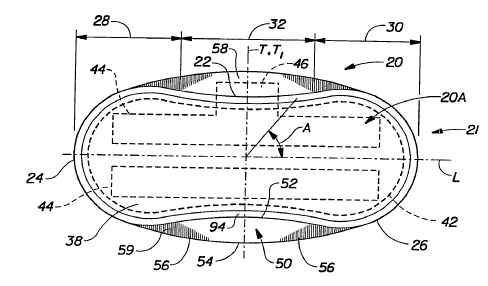
FIG. 1 shows that the main body portion 21 of the sanitary napkin 20
comprises the portion of the sanitary napkin without the side wrapping
elements.
The main body portio~l 21 has two spaced apart longitudinal edges 22, two
spaced
apart transverse or end edges (or "ends") 24, which together form the
periphery 26
of the main body portion. The main body portion also has two end regions,
which
are designated first end region 28 and second end region 30. A central region
32 is
disposed between the end regions 28 and 30. The end regions 28 and 30 extend
outwardly in the longitudinal direction from the edges of the central region
32 about
1/8 to about 1/3 of the length of the main body portion. A detailed
description of the
CA 02225076 2001-O1-12
9
characteristics of a central region and two end regions for a sanitary napkin
is
contained in U.S. Patent4,690,680 issued to Higgins on September 1, 1987.
The main body portion 21 of the sanitary napkin 20 can be of any
thickness, including relatively thick, intermediate thickness, relatively
thin, or
even very thin (or "ultra thin"). An "ultra-thin" sanitary napkin 20 as
described
in U.S. Patents 4,950,264 and 5,009,653 issued to Osborn preferably has a
caliper of less than about 3 millimeters. The embodiment of the sanitary
napkin 20 shown in the drawings is intended to be an example of a sanitary
napkin of an intermediate thickness. The main body portion 21 of the sanitary
napkin 20 may also be relatively flexible, so that it is comfortable for the
wearer. It should be understood that the sanitary napkin shown is merely one
embodiment, and that the present invention is not limited to absorbent
articles
of the type or having the specific configurations shown in the drawings.
FIG. 2 shows the individual components of the main body portion 21 of
the sanitary napkin 20 of the present invention. The main body portion 21 of
the sanitary napkin preferably comprises at least three primary components.
These include a liquid pervious topsheet 38, a liquid impervious backsheet 40,
and an absorbent core 42 positioned between the topsheet 38 and the
backsheet 40. The topsheet, the backsheet, and the absorbent core may be
assembled in a variety of configurations known in the art (including layered
or
"sandwich" configurations and wrapped or "tube" configurations).
Several preferred sanitary napkins having main body portions that can
be provided with side wrapping elements and adapted to have the regions
with the different properties specified herein are described generally in U.S.
Patent 4,321,924, "Bordered Disposable Absorbent Article" issued to Ahr on
March 30, 1982; U.S. Patent 4,425,130, "Compound Sanitary Napkin" issued
to DesMarais on January 10, 1984; U.S. Patent 4,950,264, "Thin, Flexible
Sanitary Napkin" issued to Osborn on August 21, 1990; U.S. Patent
5,308,346, "Elasticized Sanitary Napkin" issued to PCT Publication No. WO
94/02096, published February 3, 1994; PCT
CA 02225076 2001-O1-12
10
Publication No. WO 95/07675, published March 23, 1995; and PCT
Publication No. WO 95/03025, published February 2, 1995. The main body
portion 21 of the sanitary napkin may also be comprised of one or more
extensible components such as those sanitary napkins, and the like described
in PCT Publication Nos. WO 93/01785 and 93/01786, both published
February 4, 1993.
Figures 1 and 2 show a preferred embodiment of the sanitary napkin 20
assembled in a sandwich construction in which the topsheet 38 and the
backsheet 40 have length and width dimensions generally larger than those of
the absorbent core 42. The topsheet 38 and the backsheet 40 extend beyond
the edges of the absorbent core 42 to form portions of the periphery 26. The
topsheet 38 is joined to the backsheet 40. The topsheet 38 and backsheet 40
can be joined in any suitable manner known in the art for this purpose.
Preferably, the topsheet 38 and backsheet 40 are sealed at least around the
periphery of the main body portion 21 by a peripheral crimp seal 48 where the
topsheet 38 and backsheet 40 are densified by the application of pressure or
heat and pressure.
The sanitary napkin 20 shown in FIGS. I and2 also comprises a pair of
side wrapping elements 50 that extend laterally outward beyond the
longitudinal side edges 22 of the main body portion 21 from their proximal
edges 52 to their distal edges 54. The side wrapping elements 50 can be of
any suitable size and shape. Preferably, however, the distal edges 54 of the
side wrapping elements extend outward beyond the longitudinal side edges
22 of the main body portion 21, a distance of less than or equal to one-half
the
width of the main body portion. The side wrapping elements 50 of the present
invention may have the dimensions and characteristics set forth for the panty
covering components in the aforementioned PCT Applications WO 94/02096,
95/07675 and 95/03025.
The side wrapping elements 50 can be joined to the main body portion
21 in any suitable manner. The term "joined", as used herein, encompasses
configurations in which an element is directly secured to another element by
affixing the element directly to the other element; configurations in which
the
element is indirectly secured
CA 02225076 2001-O1-12
11
to the other dement by axing the element to intermediate members) which in
turn
are axed to the other element; and con5gurations in which one element is
integral
with another element, i.e., one element is essentially part of the other
dement.
Preferably, ss shown in FIGS. 1 and 2, the side wrapping elemenu 50 are
integral
with the main body portion 21 (that is, integral extensions of the topsheet 38
and
backsheet 40). In other alternate embodiments, the side wrapping elemenu 50
can
comprise two stparue components thu are joined to the garment-facing side of
the
main body portion 21. In such alternuive embodiments, the side wrapping demenu
50 arc preferably otherwise unattached to the gsrmart~facing side of the main
body
portion 21 of the sanitary napkin 20 betwreen the poinu where they are
attached to
the main body portion and the longitudinal side edges 22 of the main body
portion.
The side wrapping demenu 50 in thex later anbodimenu can be joined to the
garment-fsang side of the main body portion 21 by any suitable attachment
mechanism. Suitable attachment mechanisms include, but are not limited to
adl>aiva, and the like. In other anbodiments, instead of comprising two
separste
componaru, the side wrapping elements 50 an comprix a single component that is
joined to tlk main body portion (which may be referred to as a 'Panty covering
component' or 'undergument covering component'). In will other anbodiments,
each side wrapping dement 50 an comprix more than one component.
The side wrapping dements 50 can be made from many of the muerials known
in the art for ux in the construction of sanitary napkins. The side wrapping
demenu
50 in the embodiment shown, in FIGS. 1 and 2 preferably comprix s laminate of
a
least two materials. Preferably, the side wrapping daneras 50 camprix s
laminate
comprising s thrx dimensional apa~aired formed film and a liquid impervious
bacJong, such ss a polyethylene Slm backsheet material. The apertured formed
film is
pcrfaably the topshett material made in accordance with U.S. Puent 4,342,314
iswed to Radd, a al. and U.S. Patent 4,463,045 issued to Ahr, a al. and
marketed
on ::rotary napkins by The Procter do Gamble Company under the name DRI-
WEAVE: The laminate has been found to be suitable where it is desirable to
perform
f orbs mechanical operations on the laminate to provide zones of greater
extaurbility in sdected regions of the laminate.
The side wrapping demenu 50 may also comprix additional layers if desired.
For instance, the body-facing side of the side wrapping demenu 50 may be
provided
with an optional soft coverstock material, such as a soft nomwoven web, to
provide
improved tactile properties adjacent the wearer's skin. Nonwoven webs suitable
for
use as a coverstock material include a product known as Spunbond PE, which was
* - Trade-mark
CA 02225076 2001-O1-12
12
obtained from Polybond, Incorporated of Waynesboro, VA, and a product* lmown
as
COROLIND PE, which was obtained from Corovin GMBH of Germany. In
addition, if desired, the side wrapping elements 50 may comprise other
optional
layers, such as layers to increase the sti$nus of the side wrapping elements
50, or
various regions thereof. Optional stiffening layers c~ comprise materials that
include, but are not limited to foams and scrims. The optional stiffening
layers can be
positioned in any suitable locuion in the side wrapping dements 50 of the
sanitary
napkin, such between the portions of the topshea and backsheet that form the
side
~PP~B ~lemenu. Preferably, however, such optional stiffening layers are
provided
on the garment-facing side of the side wrapping dements for ease of
manufacture.
In the preferred ernbodiment shown in FIGS. 1 and 2, the side wrapping
dements 50 each have at least one, and preferably have two zones of
extensibility 56
therein. The zones of extensibility 56 can be primarily extensible in the
longitudinal
direction (that is, they are extatsibke more in the longitudinal direction
than in the
transverse direction). In other embodiments, the zones of aetensibility 56 can
be
Pnmatdy extensible in the transverse direction, or in any direction between
the
longrtudinal direction and the transverse direction, or in more than one
direction.
The side wrapping dements 50 shown in FIGS. 1 and 2 have zones of
actensibility 56
~ ~ P~1Y ~t~~ble in the longitudinal direction. The extensibility of all the
zones of ability 56 of the side wrapping dements 50 can be in the same
~~on. ~ altana~va anbodiments, one or more of the zones of extensibility 56
may be exteass'ble in s different direction.
The zones of oan>stbility 56 are preferably capable of attending between
about 20~/~ and about 80'/x, more preferably between about 40'/. and about
60'/., and
most prefcabiy about 50'/. under the forces associued with folding the side
wrapping dana~tt 50 around the side edges of the crotch of a pair of panties.
Preferably, the zones of actauibility 56 are capable of such actension under
forces of
less than about 100 - 200 g:amsf per inch (about 40-80 g~cm), more preferably
under forces of less than about 50 grams f per inch (about 20g~cm). The zones
of
extensibility 56 are also preferably actensible without being dasticized or
elatticated
(that is, whore separate dastic bands are stretched and attached to the side
wrapping
dements 50 in an aaestsible condition). Further, my inherent dasticity in the
zones
of oetensibility 56 (that is, any tendency of the material comprising the
zones of
actensibility to return to its original dimension) is preferably generally
relatively low
to non-aastent. Preferably, the zones of extensibility 56 exhibit a return
force of less
than or equal to about L00 gratnsf when attended.
* - Trade-mark
CA 02225076 1997-12-18
WO 97/00655 PCT/US96/10198
13
FIG. 3 shows the preferred locations for the zones of extensibility 56 and the
manner in which the preferred amounts of extensibility in the zones of
extensibility 56
- are determined. The curved line, E, in FIG. 3 represents the location where
the
edges of a wearer's panty crotch might lie when the sanitary napkin 20 is
placed in a
pair of panties prior to the side wrapping elements 50 being folded around the
edges
of the crotch of the panties. The panty edges E cross the distal edge 54 of
the side
wrapping element 50 at two points, designated P. The zones of extensibility 56
should be located where the panty edges E cross the distal edges 54 of the
side
wrapping elements 50. The distance, D, between these two points P varies
depending on the size and style of panties. A representative distance D is
equal to
about 85 mm. FIG. 3 also shows portions 56' of the zones of extensibility 56
that are
disposed longitudinally inboard of the points P (that is, toward the
transverse
centerline T 1 of the side wrapping elements). In order to fit a wide variety
of panty
sizes and styles, it is preferred that each of the portions 56' of the zones
of
extensibility 56 between points P is capable of extending greater than or
equal to
about 10-15 mm under the aforementioned forces, and that the combined
extensibility in these portions for each side wrapping element 50 is greater
than or
equal to about 20-30 mm. The longitudinal distance between the points within
each
of the zones of extensibility 56 that are on opposite sides of the transverse
centerline
of a side wrapping element 50 is preferably between about 20 mm and about 150
mm, and more preferably is between about 30-130 mm, and most preferably is
between about 30-100 mm.
It is possible, however, that portions of the zones of extensibility 56 that
are on
opposite sides of the transverse centerline T 1 of a side wrapping element can
abut
each other at least at certain areas so that there is no separation between
the zones of
extensibility 56 . For example, the bottom portion of FIG. 3 shows that the
zones of
extensibility 56 may be extended toward the transverse centerline TI in
certain areas,
such as extensions 56" that run along the distal edge 54 of the side wrapping
elements 50. The extensions 56" provide additional extensibility along the
distal edge
54 of the side wrapping elements 56 (where additional extensibility can be
beneficial).
In addition, since the extensions 56" are relatively narrow (when measured in
the
transverse direction), they will not substantially alter the desired stiffness
of the
different regions of the sanitary napkin.
The side wrapping elements 50 can be provided with zones of extensibility 56
in a non-limiting number of different manners. The side wrapping elements 50
may,
for example, comprise a material that is substantially inextensible under the
forces
CA 02225076 2001-O1-12
14
described above. The side wrapping elements 50 can then have portions which
are
altered so that they are provided with extensible regions for the zones of
extensibility
56. The extensible regions can be created in any suitable manner, including
but not
limited to mechanically straining corrugating "ring rolling", heating and
deforming,
subjecting portions of the side wrapping elements 50 to compression between
mating
plates, forming a network of distinct regions therein to provide portions of
the side
wrapping elements with the properties of a Structural Elastic-Like Film
without added
elastic materials (or the "SELFing" process described in PCT Publication No.
WO
95/03765, published February 9, 1995. This process is described in greater
detail
below in conjunction with FIGS. 10-10C, and several of the figures which
follow).
In other embodiments, the extensible regions of the side wrapping elements
can be provided by forming the side wrapping elements out of materials having
different extensibilities. For example, the side wrapping elements 50 can be
comprised of a laminate of an extensible material and a relatively
inextensible
material. In such an embodiment, the relatively inextensible material can be
provided
in the configuration of the side wrapping elements. The inextensible material
can
then have holes cut out where the zones of extensibility 56 are to be located.
This
inextensible material can then be laminated to the extensible material to form
a side
wrapping element with zones of extensibility 56 at the locations where the
holes were
cut out of the inextensible material.
The embodiment shown in FIGS. 1-3 has zones of extensibility 56 formed by
ring rolling (or pre-corrugating) two regions of each of the side wrapping
elements
50. Suitable methods for ring rolling are described in U.S. Patent 4,107,364
issued
to Sisson on August 15, 1978, U.S. Patent 4,834,741 issued to Sabee on May 30,
1989, U.S. Patent 5,143,679 issued to Gerald M. Weber, et al. on September 1,
1992, U.S. Patent 5,156,793 issued to Kenneth B. Buell, et al. on October 20,
1992,
and U.S. Patent 5,167,897 issued to Gerald M. Weber, et al. on December 1,
1992.
The side wrapping elements 50 in the embodiment shown in FIGS. 1-3 are
provided with ring rolled corrugations having fold lines (or ridges and
valleys) 59, that
are oriented generally in the transverse direction. This provides zones of
extensibility
56 that are primarily extensible in the longitudinal direction. In other
embodiments,
the fold lines could be angled away from the longitudinal centerline L. The
fold lines
59 can form any angle, A, with the longitudinal centerline, between
CA 02225076 1997-12-18
WO 97/00655 PCT/US96/10198
greater than 0° and less than or equal to 180°. The fold lines
59 in the various
possible alternative embodiments can, for example, form an angle of between
about
40° - 45° with the longitudinal centerline L. In cases in which
the fold lines 59 form
an angle of less than 45°, the orientation of the extensibility may be
primarily in the
transverse direction.
The side wrapping elements 50, as shown in FIG. 3, preferably have a
trapezoidally-shaped intermediate region or zone 58 located between at least
portions
of the zones of extensibility 56. This intermediate region 58 preferably has a
distal
edge portion that forms a portion of the distal edge 54 of the side wrapping
elements.
However, as shown on the side wrapping element 50 on the bottom of FIG. 3,
embodiments can be constructed in which the distal edge portion of the
intermediate
region 58 may be laterally inboard of the distal edge 54 of the side wrapping
elements
50. The length D1 shown in FIG. 3 of the distal edge portion, is preferably at
least
about 20 mm, and more preferably about 30 mm. The intermediate region 58 is
preferably less extensible than the portions of the side wrapping elements 50
that
comprise the zones of extensibility 56. The intermediate region 58 provides
the side
wrapping elements 50 with greater resistance to crumpling so that the side
wrapping
elements will fold over the panty elastic, rather than crumple, when they are
subject
to compression by the wearer's thighs.
The configuration and location of the zones of extensibility 56 in the
embodiment shown in FIGS. 1-3 is preferred for several reasons. The fact that
the
zones of extensibility 56 are spaced apart and separated by the stiffener
intermediate
region 58 provides improved resistance to undesirable crumpling while
providing
more control over the manner of folding around the edges of the wearer's
panties.
The side wrapping elements 50 will typically fold at those locations in the
zones of
extensibility 56 and the intermediate region 58 between the points where the
panty
edges cross the distal edges 54 of the side wrapping elements 50 that are
situated
along the panty elastics. The presence of the stiffer intermediate regions 58
makes
the side wrapping elements sturdier and capable of more reliable folding than
if the
side wrapping elements 50 were made entirely extensible and/or were made of
"' materials having the same stiffness over their entire area.
The stiffer intermediate region 58 also helps to maintain panty elastic
coverage
when the wearer pulls her panties down to check the sanitary napkin 20 for
soiling,
and then pulls her panties back up. The stiffer material ensures that the side
CA 02225076 1997-12-18
WO 97/00655 PCTJCTS96/10198
16
wrapping elements 50 will go back into place in a dovmwardly folded
configuration
around the edges of t:he wearer's panties.
The sanitary napkin 20 of the present invention preferably also comprises a
flexible bending zone: (or hinge) 94. The bending zone 94 provides at least
one axis
about which the side wrapping elements 50 may fold relative to the main body
portion 21. The side wrapping elements 50 preferably at least initially bend
around
the edge of the wearer's panties along at least a portion of the bending zone
94. The
bending zone 94 is preferably located between at least a portion of the main
body
portion 21 of the sanitary napkin 20 and the distal edge 54 of the side
wrapping
elements 50. The bending zone 94 preferably has little to no bending
resiliency. As a
result, the side wrapping elements 50 will have very little tendency to return
to their
original extended position after they fold along the edges of the wearer's
undergarment. The side wrapping elements 50 with the bending zone 94 described
herein preferably function by adapting to the configuration of the edges of
the panties
unlike clasp structures described in the patent literature which may
forcefully alter the
configuration of the sides of the wearer's undergarment.
The bending zone 94 can comprise any suitable structure which satisfies these
criteria. The bending; zone 94 can comprise areas of the sanitary napkin which
are
densified, scored, are~.as which are not laminated but are surrounded by
laminated
regions, and areas wruch are mechanically deformed, or which are otherwise
formed
into structures which provide enhanced flexibility. In the preferred
embodiment
shown in FIG. 1, the bending zone 94 comprises the peripheral seal 48 along
the
outer edges of the main body portion where the topsheet 38 and backsheet 40
extend
beyond the longitudinal edges of the absorbent core 42 and are joined
together.
The peripheral seal 48 is provided with enhanced flexibility relative to the
absorbent core 42. This is possible because the seal 48 preferably does not
contain
absorbent material (or contains less absorbent material than the absorbent
core). The
elimination of this layer of material makes the portion of the sanitary napkin
containing the peripheral seal 48 thinner and, thus, more flexible than the
portion of
the sanitary napkin containing the absorbent core. The peripheral seal 48 is -
preferably also more flexible than the adjacent intermediate region 58 of the
side
wrapping element. This is possible in the embodiment shown in FIG. 1 because
the '
peripheral seal 48 comprises a densified region in the extension of the
topsheet 38
and backsheet 40. The means for providing the sanitary napkin 20 with a region
having enhanced flexibility relative to other portions of the sanitary napkin,
however,
CA 02225076 1997-12-18
WO 97!00655 PCT/US96/10198
17
is not limited to the use of densified regions such as crimped seals. Any
other
suitable means for providing the sanitary napkin 20 with enhanced flexibility
in this
region can be used instead of, or in addition to, a crimp seal.
The flexible bending zone 94 may extend completely around the outer
perimeter of the main body portion 21 as shown in FIG. 1. In other
embodiments,
however, the bending zone 94 may only extend around a portion of the perimeter
of
the main body portion 21. For example, the bending zone 94 may only extend
along
the juncture between the side wrapping elements 50 and the main body portion
21.
The juncture comprises the lines or areas where the side wrapping elements 50
extend from, or are otherwise joined to the main body portion 21 (although it
is not
necessary that there be a precise line of demarcation between the side
wrapping
elements and the main body portion). In cases where the bending zone 94
extends
along the juncture, as shown in the drawings, the bending zone 94 may extend
the
entire length of the juncture between the side wrapping elements 50 and the
main
body portion 21, or only a portion of the length thereof.
The flexible bending zone 94 may be positioned at any suitable location
between at least a portion of the main body portion 21 and the distal edge 54
of the
side wrapping elements 50. The bending zone 94 can, thus, be located along the
juncture of the side wrapping elements 50 and the main body portion 21, in the
region of the juncture, or outboard of the juncture. The bending zone 94,
thus, need
not be immediately adjacent to the longitudinal side edge 22 of the main body
portion
21 as shown in FIG. 1. When the bending zone 94 does not comprise a crimp
seal,
the hinge structure may be disposed outboard of the juncture, and is
preferably
located where the elasticized side edges of the wearer's pantries cross the
side
wrapping elements.
The flexible bending zone 94 may be provided in any suitable shape. The
bending zone 94 may be comprised of linear segments, curvilinear segments, or
some
regions of the bending zone 94 may be comprised of linear segments, and some
regions may be comprised of curvilinear segments. Preferably, the bending zone
94
is configured that the portions thereof that are adjacent to the central
region 32 of the
main body portion are located at least as close to the longitudinal centerline
of the
sanitary napkin, and more preferably, closer to the longitudinal centerline 7L
than the
portions of the bending zone 94, if any, that are situated adjacent to the end
regions
28 and 30 of the sanitary napkin. Most preferably, as shown in FIGS. 1 and 2,
the
CA 02225076 1997-12-18
WO 97/00655 PCT/US96/10198
18
bending zone 94, is preferably concave when looking at the same from the
distal
edges 54 of the side wrapping elements 50.
The sanitary napkin 20 of the present invention can (as is apparent from the
foregoing discussion), be thought of as having several regions with different
bending
properties, and several regions with different deformation properties (or
different
extensibility characteristics).
In preferred ernbodiments, the sanitary napkin 20 has at least three distinct
regions with different bending properties. These are shown in FIG. 3. These
regions
are designated as a first region 90 that has a first bending modulus, a second
region
92 that has a second bending modulus, and a third region 94 that has a third
bending
modulus. Preferably, as shown in FIG. 3, the first region 90 comprises the
portion of
the main body portion 21 of the sanitary napkin that cotains the absorbent
core 42.
This first region 90 preferably has the highest bending modulus (that is, is
the stiffest)
of the three regions. The second region 92 preferably comprises the
intermediate
regions 58 of the side wrapping elements 50. The second region 92 preferably
has a
bending modulus which is between the bending moduli of the first and third
regions,
92 and 94. The third region 94 comprises the bending zone, and is preferably
the
most flexible of the three regions.
FIG. 3 also shows that the sanitary napkin 20 preferably has at least two
distinct regions with different degrees of extensibility under a given force
or range of
forces (that is, different deformation moduli). These regions comprise the
zones of
extensibility 56 and the intermediate region 58 located between the zones of
extensibility 56. Tt~e zones of extensibility 56 are more extensible than the
intermediate regions :58. That is, the zones of extensibility 56 have a first
lower
deformation modulus" M1, which is lower than the second deformation modulus,
M2, of the intermediate regions 58.
It should be understood that the embodiment shown in FIGS. 1-3 is a preferred
embodiment, and that there may be variations of the structure illustrated that
have
either fewer, or additional regions with different bending or deformation
properties.
For instance, in the embodiments shown in FIGS. 9, 11-14, and 16, the side
wrapping
elements 50 may also be provided with stiffer end regions 100 that are located
longitudinally outboard of the zones of extensibility 56 to prevent the panty
elastics
from undesirably flipping over the ends of the side wrapping elements 50.
Preferably,
the stiffer regions 100 of the side wrapping elements 50 have the same bending
CA 02225076 1997-12-18
WO 97/00655 PCT/US96/10198
19
modulus as the intermediate regions. However, the bending modulus of the
stiffer
regions 100 may be more or less as long as the bending modulus of these
regions is
large enough to prevent the undesirable flipping of the ends of the side
wrapping
elements 50. There may also be other ways to describe the properties of the
embodiment shown in FIGS. 1-3. For example, the zones of extensibility 56 can
be
considered to comprise fourth regions which have a fourth bending modulus
which is
preferably lower than the second regions 92, and possibly even lower than that
of the
third regions 94.
The garment surface 20B of the sanitary napkin 20 may include, and preferably
does include, fasteners for attaching the sanitary napkin to the wearer's
undergarment. Figures 1 and 2 show the central pad fastener 44 which is
adapted to
secure the main body portion 21 of the sanitary napkin to the crotch region of
an
undergarment. Any types of fasteners known in the art, such as adhesive
fasteners
and mechanical fasteners can be used. Fasteners comprising adhesives have been
found to work well for this purpose, with pressure-sensitive adhesives being
preferred. Fig. 1 shows a preferred arrangement which utilizes a pair of
spaced apart
longitudinally-oriented strips or zones of adhesive 44 that are centered about
the
longitudinal centerline L. Before the sanitary napkin 20 is placed in use, if
an
adhesive fastener is used, the adhesive is typically covered with a removable
cover
strip or release liner in order to keep the adhesive from sticking to a
surface other
than the crotch portion of the panty prior to use. Suitable release liners are
described
in the U.S. Patent 4,917,697. A particularly preferred release liner which
also serves
as an individual package for wrapping the sanitary napkin is described in U.S.
Patent
4,556,146 issued to Swanson, et al.
The sanitary napkin 20 of the present invention is used by removing any
release
liner and thereafter placing the sanitary napkin 20 in a panty as shown in
FIG. 4 so
that the central pad fastening adhesive (or other fastener) 44 contacts the
panty and
maintains the sanitary napkin in position within the panty during use. The
side
wrapping elements 50 automatically fold along the sides of the wearer's
panties by
the simple action of the wearer pulling up her panties. The side wrapping
elements
50 then assume an in-use position, one nonlimiting example of which is shown
in
FIG. 4.
FIG. 1 shows that the sanitary napkin 20 can also be provided with optional
fasteners on the side wrapping elements 50. FIG. 1 shows that the
longitudinally-
oriented zones of adhesive may optionally have a central lateral extension 46
of
CA 02225076 1997-12-18
WO 97/00655 PCT/(JS96/10198
adhesive (one of which is shown in FIG. 1). The central lateral extension 46
serves
to adhere the side wrapping elements 50 to the undergarment. The central
lateral
extension 46 of adhesive maintains the side wrapping elements 50 around the
elasticated edges of the crotch portion of the wearer's undergarments during
vigorous
motions by the wearer (although such extensions of the fasteners are generally
not
required under normal circumstances). The central lateral extension 46 of
fastener
adhesive can serve to secure the side wrapping elements 50 to the top of the
wearer's
panties, and/or to the: underside of the wearer's panties as shown in FIG. 5.
The side
wrapping elements 50 can be secured to the underside of the wearer's panties
by the
wearer, or this can happen automatically when the wearer's thighs press the
side
wrapping elements 50 against the underside of the panty crotch, especially
when the
wearer's thighs are relatively large. The central lateral extensions 46 are
preferably
located in the stiffer iintermediate regions 58 of the side wrapping elements
50. The
central lateral extensions 46 are preferably contiguous with the
longitudinally-
oriented zones of adhesive, although this is not required. The presence of the
intermediate region 58 provides an advantage in constructing embodiments that
are
provided with such central lateral extensions of adhesive. Since there is no
need to
provide the intermediate region 58 with extensibility, it is typically not
corrugated so
that it is easier to apply an adhesive-type fastener to the garment-facing
side of the
intermediate region 58.
FIG. 6 shows a phenomenon that may occur when the sanitary napkin is
provided with side wrapping elements that have fasteners with central lateral
extensions 46. The side wrapping elements 50 are shown as folding around a
side
edge E of a crotch portion of a wearer's undergarment, U, at a longitudinally-
oriented fold line F. It has been found that the central lateral extensions 46
can be of
such a size and configuration that when the sanitary napkin is worn in narrow
panty
crotches, the fold lane F divides the central extensions 46 into two portions
comprising a first portion 46A and a second portion 46B. In such cases, the
fold line
is disposed far enough outboard of the side edge of the crotch portion of the
undergarment so that: a portion of said side wrapping element 50 comprising
first
and second portions SOA and SOB, respectively, of the side wrapping element 50
with the adhesive portions 46A and 46B thereon overlap and adhere to each
other
outboard of the side edge of said undergarment so that the side wrapping
element ,
forms a structure which can "grasp" or "pinch" the longitudinal edge of the
panty
crotch. This not only assists in maintaining the side wrapping elements 50
around the
panty crotch when the panties are in place against the wearer's body, but also
CA 02225076 1997-12-18
WO 97/00655 PCT/US96/10198
21
maintains the side wrapping elements 50 in position when the wearer pulls her
panties
down to check the sanitary napkin.
The operation of the side wrapping elements 50 utilized on the present
invention is distinguishable in several aspects from that of conventional side
flaps.
First, placing a sanitary napkin having conventional flaps in a pair of
panties and
pulling up the panties will not consistently provide the automatic sustained
wraparound feature of the present invention. There are several reasons for
this.
Conventional flaps are not provided with resistance to crumpling so that they
will
tend to crumple in use, particularly when the wearer's thighs exert
compressive forces
on the flaps. Conventional flaps are also not provided with zones of
extensibility, so
they will generally not wraF around and conform to the panties. Li those cases
where
conventional flaps do wrap around the panties, since conventional flaps do not
have
zones of extensibility they will not consistently stay wrapped. Second,
conventionally-sized flaps will have excess flap material that hangs down
underneath
the panties during wear. This material can move around excessively underneath
the
panties and be uncomfortable for the wearer. The side wrapping elements of the
present invention, on the other hand, have a span that is ideally just wide
enough to
wrap around the elastic-containing edges of the panties, but no wider,
avoiding the
problems associated with excess flap material.
Numerous alternative embodiments of the present invention are possible. For
example, the side wrapping elements are preferably mirror images of each
other, and
are symmetrical about the longitudinal centerline. However, it should be
understood
that the shape and location of the side wrapping elements described herein are
those
of a preferred embodiment, and other embodiments are also possible. For
example,
while the side wrapping elements SO are shown as extending from each
longitudinal
edge of the main body portion, there may only be one side wrapping element
extending from one of the edges of the main body portion. Further, the side
wrapping elements 50 may be offset along the longitudinal centerline more
towards
one end edge of the main body portion than the other.
- The side wrapping elements may, in addition, extend outward from a variety
of
different areas of the main body portion 21. FIG. 2 shows an example of a
sanitary
. napkin having side wrapping elements 50 that extend from a plane which is
located
approximately midway between the plane of the body side 20A of the main body
portion of the sanitary napkin and the plane defined by the garment-facing
side 20B
of the main body portion 21. FIG. 7 provides an example of a sanitary napkin
having
CA 02225076 1997-12-18
WO 97/00655 PCT/US96/10198
22
side wrapping elements 50 that extend from the same plane as the body side 20A
of
the main body portion 21. FIG. 8 provides an example of a sanitary napkin
having
side wrapping elements SO that extend from the same plane as the garment-
facing
side 20B of the main body portion 21.
The sanitary napkin 20 may also be provided with a variety of other types of
hinge structures. For example, instead of comprising the crimped seal area
shown
in FIGS. 1-3, the hinge can comprise an unsealed region of a laminate
structure, or a
mechanically altered region of the side wrapping elements.
FIG. 9 shows .an embodiment in which portions of the topsheet 38 and the
backsheet 40 that extend beyond the edges of the absorbent core 42 to form
side
wrapping elements 50 are preferably laminated together, such as by adhesives,
over
generally their entire inwardly-facing surfaces, except for the arcuate
regions 88. The
bending zones 94 in this case, comprise the arcuate regions 88. The arcuate
regions
88 are provided with greater flexibility than the laminated portions of the
side
wrapping elements 50 because the portions of the topsheet 38 and backsheet 40
that
lie within the arcuate regions 88 each flex independently as single layer
components.
FIG. 9 shows that the sanitary napkin (that is, the main body portion thereof)
can
also be provided with optional side channels 78 such as those described in
U.S.
Patent 5,308,346 issued to Speller, et al. Side channels 78 can be similarly
provided
on any of the embodirnents described herein.
FIGS. 11-16 show several examples of sanitary napkins having hinge
structures formed by mechanically altered portions of the side wrapping
elements 50.
FIG. 11 shows a hinge structure 94 which comprises a short, linear,
longitudinally-
oriented, mechanically-deformed region that is located adjacent the central
region of
the main body portion. The sanitary napkin 20 (or side wrapping elements 50)
can be
provided with mecharucally deformed regions in any suitable manner that
provides a
hinge structure with increased flexibility and that does not result in tearing
of any
portions of the sanitary napkin. It has been found that many processes for
providing
the sanitary napkin with extensibility are particularly suitable for providing
selected
regions of the side wrapping elements 50 with enhanced flexibility. The hinge
structure 94 of the side wrapping element 50 can, for instance, be ring
rolled, or
more preferably, as shown in FIG. 11, formed so that is has a strainable
network
region therein, or "SF?LFed". The SELFing process and structures formed
thereby
are described in greater detail below in conjunction with FIGS. 10-IOC.
CA 02225076 1997-12-18
WO 97!00655 PCT/LTS96/10I98
23
These structures (ring rolled structures and SELF struct~sres) are especially
preferred because the alternating ridges and valleys can form a plurality of
flexible
bending axes for the side wrapping elements 50. The structures also provide
the
flexible bending zones 94 with a degree of extensibility. The extensibility
allows the
portions of the side wrapping elements 50 in the bending zones 9~4 to expand
slightly
in the transverse direction to better fold around the curved sides of the
wearer's panty
crotch. Providing a bending zone by SELFing is additionally preferred because
the
unformed less extensible bands 64 of the strainable network will serve like
"beams"
that tend to provide the formed regions with slightly more integrity so the
side
wrapping elements 50 will be less likely to droop excessively at the hinge
structures
94.
The process of forming a strainable network in a material or a laminate of
materials such as the side wrapping elements 50 is referred to form
convenience as
forming a Structural Elastic-Like Film or "SELF" material because the base
material
into which the strainable network is formed is often a film (or has at least
one
component which is a film). The SELFing process is preferred for providing the
side
wrapping elements 50 with a bending zone 94 because (like ring rolling) such
an
operation can be readily adapted for use in high speed manufacturing
operations.
Further, the process of forming a strainable network in a material is highly
preferred
because it can be adapted to produce a virtually unlimited number of patterns
to
tailor the configuration and characteristics of the bending zone 94.
The characteristics of the strainable network 62 of a SEL Fed region will be
discussed with reference to FIGS. 10-IOC. FIGS. 10-IOC show enlarged views of
a
web material 60 having a strainable network 62 formed therein. The term
"strainable
network", as used herein, refers to an interconnected and interrelated group
of
regions which are able to be extended to some useful degree in a predetermined
direction. FIGS. 10 and l0A show the web material 60 in an untensioned
condition.
The strainable network 62 comprises at least two distinct and dissimilar
regions.
These comprise at least a first region 64 and a second region 66.
In the simplified embodiment shown in FIGS. 10 and 10A, the strainable
network 62 includes a plurality of first regions 64 and a plurality of second
regions
66. As shown in FIGS. 10 and 10A, the first regions 64 are substantially
planar
regions. That is, the material within the first region 64 is in substantially
the same
condition before and after the formation step undergone by web material 60.
The
second regions 66 include a plurality of continuous, interconnected,
deformations 74
CA 02225076 1997-12-18
WO 97/00655 PCT/US96/10198
24
which extend alternately beyond the plane of both the first and second
surfaces (64A
and 648, respectively) of the first region 64. In other embodiments, the
deformations 74 may extend beyond the plane of only one of the first 64A or
the
second 64B surfaces of the first region 64.
FIG. 10 shows that the web material 60 having the strainable network 62
formed therein has a longitudinal centerline (or axis), 1, and a lateral
centerline (or
axis), t. In the sanitary napkin embodiment shown in FIG. 11, the longitudinal
centerline, 1, of the strainable network is shown as being rectilinear and
generally
oriented in the transverse direction. However, the longitudinal centerline, l,
is not
limited to such a configuration and orientation. The longitudinal centerline,
I, can be
rectilinear, curvilinear, or partially rectilinear and partially curvilinear.
The
longitudinal centerline, l, of the strainable network 62 can also be oriented
in other
directions, if desired.
FIG. 10 shows that the first regions 64 of the strainable network 62 have a
first axis 68 and a second axis 69, wherein the first axis 68 is preferably
longer than
the second axis 69. In the simplified embodiment shown, the first axis 68 of
the first
region 64 is substantially parallel to the longitudinal axis, 1, of the
strainable web
material 60 while the second axis 69 is substantially parallel to the
transverse axis, t,
of the strainable web material 60. The second regions 66 of the strainable
network
62 also have a first antis 70 and a second axis 71. The first axis 70 of the
second
region 66 is substantially parallel to the longitudinal axis I of the web
material 60,
while the second axis 71 is substantially parallel to the transverse axis t of
the web
material 60. In the version of the web material shown in FIGS. 10 and 10A, the
first
regions 64 and the second regions 66 are substantially linear, extending
continuously
in a direction substantially parallel to the longitudinal axis 1 of the
strainable web
material. In other embodiments, the second regions 66 can be curvilinear, or
partially
rectilinear and partially curvilinear.
While the enhanced flexibility of the SELFed region is of primary interest in
the bending zone 94, the SELF structure also provides a portion of the side
wrapping
element 50 with a degree of extensibility. FIGS. 10A, B, and C show the manner
in
which the web materi:~l 60 with the strainable network 62 may exhibit at least
two
significantly different stages of controlled resistive force to elongation
when
subjected to an applied elongation in a direction parallel to a predetermined
axis. The
strainable network 62 exhibits first resistive forces to the applied
elongation (which
develop between the :,tage shown in FIG. l0A and the stage shown in FIG. lOB).
CA 02225076 1997-12-18
WO 97!00655 .. PCT/US96I10198
The first resistive forces occur until the elongation of the web is sufficient
to cause a
substantial portion of the second regions 66 to enter the plane of applied
elongation,
as shown in FIG. lOB. After the web material 60 reaches the stage shown in
FIG.
lOB, it exhibits second resistive forces to further elongation (as illustrated
by FIG.
lOC). Typically, when used in regions of the side wrapping elements 50
described
herein, the web material will be within the first stage of resistance to
elongation so
the various portions of the strainable network 62 will only extend to the
stage shown
in FIG. l OB and adjust so as to relax back to the stage shown in FIG. 10A.
The SELFed region of the side wrapping elements 50 is created by forming
the strainable network 62 into the web material 60. As used herein, the term
"forming" refers to the creation of a desired structure or geometry upon the
web
material 60 that will substantially retain the desired structure or geometry
when it is
not subjected to any externally applied elongations' or forces. Suitable
methods for
forming a strainable network into a web material include, but are not limited
to
embossing by mating plates or rolls, thermoforming, high pressure hydraulic
forming,
and casting.
The laminate (or other web) comprising the side wrapping elements 50 into
which the strainable network 62 is formed can comprise a base material (or
laminate)
that has a relatively low extensibility under the forces that the sanitary
napkin is
normally subjected to when worn. When the strainable network 62 is formed
therein,
however, the base material can be made extensible under pre-selected forces
such as
those that the sanitary napkin is normally subjected to when worn.
The depth and number of deformations 74 in the strainable network 62 can be
varied to control the applied force or elongation required to extend the
SELFed
regions of the side wrapping elements 50. In one embodiment, the deformations
74
are formed by two rigid plates having outer dimension of 5.0" by 12" by 0.75"
( 12.7
cm by 30.5 cm by 2 cm). On one surface of each plate are a series of meshing
teeth
which are substantially triangular in cross section and measure 0.030" (0.76
mm) at
their bases and taper to a vertex with a radius of 0.008" (0.2 mm) at the top.
The
- centerlines of the teeth are spaced evenly and at 0.030" (0.76 mm)
increments. On
the "toothed" side of one plate, a series of grooves are cut which are
parallel to each
other and perpendicular to the evenly spaced teeth. These grooves measure
0.031"
(0.8 mm) wide and are continuous over the entire length of the plate, and are
spaced
at a distance of 0.25" (6.4 mm) on center. These grooves correspond to the
undeformed regions of the base material. The preferred base material is placed
CA 02225076 1997-12-18
WO 97/00655 PCT/US96/10198
26
between the plates in a hydraulic press having platens larger than the plates
to evenly
distribute pressure. The plates are compressed under a load of at least 4,000
pounds
(1,800 Kg). The formed web material is then removed from between the plates.
The
available stretch or elongation is increased if for a given number of
deformations, the
height or degree of deformation imparted to the web material is increased.
Similarly,
the available stretch or elongation is increased if for a given height or
degree of
deformation, the number or frequency of deformations is increased. The mating
plates can be configured to create any of the patterns for the hinge
structures 94 on
the sanitary napkins shown in the drawings.
FIG. 12 shows a~ hinge structure 94 which comprises a concave region of a side
wrapping element 50 that~also extends generally in the longitudinal direction.
FIG.
12 shows an example of an embodiment where the hinge region 94 extends the
entire
length of the juncture of the side wrapping element with the main body
portion. The
hinge structure 94 shown in FIG. 12 is preferably formed by SELFing the
desired
concave region of the side wrapping element 50. The concave region is formed
so
that the ridges defined by the deformations 74 of the strainable network of
the
formed region are cursrilinear. The deformations 74 are oriented in same
direction as
boundaries of the concave region (that is, in the same direction as the edges
of the
hinge regions 94).
FIG. 13 shows another hinge structure 94 which comprises a concave region
of the side wrapping element 50 that also extends along the juncture of the
side
wrapping element with the main body portion of the sanitary napkin. In the
embodiment shown in FIG. 13, the hinge structure 94 is formed so that the
ridges
and valleys 59 oriented perpendicular to the transverse centerline T of the
sanitary
napkin. The ridges and valleys 59 of the corrugations are oriented at an angle
to the
boundaries of the concave hinge structure 94. The hinge structure shown in
FIG. 13
may be formed by rung rolling the desired concave region of the side wrapping
elements 50.
FIG. 14 shows a particularly preferred mechanically-deformed hinge structure
94 which combines features from some of the embodiments shown in the preceding
figures. In the embodiment shown in FIG. 14, the hinge structure 94 comprises
a
concave SELFed region (similar to that of the embodiment shown in FIG. 12).
The
ridges defined by the deformations 74 of the SELFed region in FIG. 14,
however, are
linear and oriented in i:he longitudinal direction. The ridges are, thus,
oriented at an
angle to the boundaries of the concave region 94. In order to show where the
side
CA 02225076 1997-12-18
WO 97/00655 PCT/US96/10198
27
wrapping element 50 might fold, a dashed line, E, shows an example of where
the
wearer's panty elastics might be located relative to the hinge 94 and the
zones of
extensibility 56 when the sanitary napkin is placed in the wearer's panties.
The side
wrapping element 50 will preferably fold along line E. In addition, while
there is no
need for a crimp seal in the embodiment shown in FIG. 14 since the extensions
of the
topsheet and backsheet are preferably laminated together by adhesives, an
embodiment can be constructed which is provided with a crimp seal, and the
hinge
structure 94, or at least a portion of the hinge structure 94, could be
located
outboard of the area of the crimp seal.
FIG. 1 S shows a particularly preferred mechanically-deformed hinge structure
94 for use on embodiments in which the side wrapping elements 50 are separate
elements. In the embodiment shown in FIG. 15, the side wrapping elements 50
comprise separate components that are joined to the garment-facing side 20B of
the
main body portion 21. The hinge structure 94 comprises a longitudinally-
oriented
SELFed region that extends the full length of the juncture of the side
wrapping
element 50 with the main body portion 21. Preferably, the hinge structure 94
comprises two spaced apart SELFed zones in which the ridges defined by the
deformations 74 are oriented in the longitudinal direction. The two spaced
apart
SELFed zones allow the side wrapping elements 50 to fold more easily around
the
crotch edges of a variety of panties having a variety of different size crotch
shapes
and widths. FIG. 15 also shows that a substantial portion of the hinge
structure 94
can be positioned underneath the main body portion 21 in such an embodiment.
In
addition, FIG. 15 shows that at least a portion of the hinge structure 94 may
be
disposed outboard of the crimp seal 48. This aids the side wrapping elements
in
fitting a wider variety of panty crotch sizes.
FIG. 16 shows another alternative hinge structure 94. In the embodiment
shown in FIG. 16, the hinge structure 94 comprises a region of the side
wrapping
element 50 which is provided with two concentric concave score lines which are
oriented side-by-side.
A virtually unlimited number of variations of the embodiments described herein
are possible. For example, the hinge structure can comprise a continuous
region, or
a plurality of spaced apart intermittent regions. In addition, instead of only
being
formed of curvilinear segments or regions, the hinge structure can be
comprised of
rectilinear segments (or regions), curvilinear segments (or regions), or both
rectilinear and curvilinear segments (or regions). Further, instead of being a
separate
CA 02225076 2001-O1-12
28
structure from the zones of extensibility, the hinge structure and the zones
of
extensibility may be portions of a continuous structure. For example, the
hinge
structure 94 and the zones of extensibility 56 could comprise deformed areas
having
a configuration in which the hinge portion could gradually transition into
portion of the
structure that comprises the zones of extensibility. Such an embodiment might
comprise continuous ridges that are arranged in the configuration of a series
of
concentric concave ridges and valleys. The features shown and described herein
for
the various embodiments can also be combined in any other suitable ways to
form
still more alternative embodiments.
The present invention is also applicable to other types of absorbent articles
worn in the crotch region of an undergarment such as pantiliners and
incontinence
articles. The terms "panty liner" or "pantiliner" refer to absorbent articles
that are less
bulky than sanitary napkins which are generally worn by women between their
menstrual periods. Suitable absorbent articles in the form of pantiliners that
can be
provided with the side wrapping elements described herein are disclosed in
U.S.
Patent 4,738,676 entitled "Pantiliner" issued to Osborn on April 19, 1988.
The term "incontinence article" refers to pads, undergarments (pads held in
place by a suspension system of same type, such as a belt, or the like),
inserts for
absorbent articles, capacity boosters for absorbent articles, briefs, bed
pads, and the
like, regardless of whether they are worn by adults or other incontinent
persons.
Suitable incontinent articles that can be provided with the side wrapping
elements
described herein are disclosed in U.S. Patent 5,300,054 issued to Feist, et al
on April
5,1994 and U.S. Patent 5,304,161 issued to Noel, et al. April 19, 1994.
It is expressly not admitted that any of the documents referred to herein
teach
or disclose the present invention. It is also expressly not admitted that any
of the
commercially available materials or products described herein teach or
disclose the
present invention.
While particular embodiments of the present invention have been illustrated
and described, it would be obvious to those skilled in the art that various
other
changes and modifications can be made without departing from the spirit and
scope
of the invention.