Note: Descriptions are shown in the official language in which they were submitted.
CA 0222~179 1997-12-19
W O 97/02156 PCT~US95/08638
IMPROVED RT~CROUT CONTROL ~Y~'l~
BACKGROUND OF THE I~v~-lloN
1. FIELD OF THE l~v~llON
The present invention relates to an improved
blackout control system for lighting control systems
installed within an emergency or police vehicle for
altering the control of the lighting features of the
vehicle. The blackout control system comprises an
improved control panel unit, a harness unit and a
control unit. The improved blackout control system of
the present invention pertains to those lighting
control systems installed within emergency or police
vehicles for blacking out selectively one or more of
the following vehicle lighting devices: one or both
headlights, interior dome light, brake lights, tail
lights, back-up lights, dashboard lights, and the
control panel lights to render the vehicle less
visible to those outside the vehicle. Several bypass
plug-in units are provided for the convenience of
bypassing the improved blackout control system in the
event servicing of different control systems is
reguired or i~ a return to the original lighting
system is desired without expensive removal of the
blackout control system.
2 5 2. DESCRIPTION OF THE PRIOR ART
Lighting control devices for altering the
conventional lighting features of a vehicle are
located between the switching arrangements of the
vehicle, such as the running lights switch, the high
beam switch, etc., and the lights under their control.
These devices allow for special lighting features to
be added to the conventional lighting features of the
vehicle. Some of the devices allow for an override of
the special lighting ~eatures to allow the lighting
features to operate in the conventional manner when
desired by the userO
SUBSTITUTE SHEET (RULE 26)
CA 0222~179 1997-12-19
W O 97/02156 PCT~US95/08638
U.S. Patent No. 4,037,195 issued July 19, 1977, to
Jack Edward Wojslawowicz describes a vehicular signal
light control system which includes silicon-
controlled-rectifiers of the gate-turn-off type to
selectively control the current to the running lights.
U.S. Patent No. 4,249,160 issued February 3, 1981,
to Graham R. Chilvers describes a vehicle mounted
light activated control system for operating warning
lights which includes a light sensor and a comparator.
The comparator then triggers a time delay threshold
device which switches on the warning lights for ten
seconds, and only when the sensed light intensity of
an approaching vehicle exceeds a threshold.
U.S. Patent No. 4,678,925 issued July 7, 1987, to
Diethelm Grocke describes a dashboard lighting switch
and switch lever for a motor vehicle.
U.S. Patent No. 4,812,808 issued March 14, 1989, to
Larry F. Ulrich describes an electronic control
circuit ~or controlling vehicle lights. An electronic
circuitry board which has emergency circuitry to
include tail lights with brake lights, front running
lights, turn indicator lights with a switch, an
emergency switch, and a brake light switch.
U.S. Patent No. 4,939,503 issued July 3, 1990, to
Carl S. Swanson describes a wiring device system for
a towed vehicle which couples the signal lights of
both vehicles.
U.S. Patent No. 5,081,565 issued January 14, 1992,
to Ali M. Nabha et al., describes a daytime running
light system for a vehicle by employing level sensing
comparators to effect reduced illumination of the high
beam headlamps.
None of the above inventions and patents, taken
either singly or in combination, is seen to describe
the instant invention as claimed.
.
CA 0222~179 1997-12-19
W O 97/02156 PCT~US95/08638
STlT ~T~y OF I~HE lNV~NllON
The device of the present invention provides for an
improved blackout switch panel for a blackout control
system having a wiring harness insertable within an
5 emergency or police vehicle. The wiring harness is
inserted within the already existing wiring
arrangement of the vehicle controlling the various
lighting features of the vehicle. Attachable to the
wiring harness is a control unit which, under the
10 control of the inventive switching panel located
within easy reach of the driver, may interrupt certain
lighting features of the vehicle.
Bypass plug-in units are provided for the
convenience of bypassing the three improved blackout
15 control systems in the event servicing of the control
system is required or if a return to the original
lighting system is desired without expensive removal
of the blackout control system.
More particularly, certain lighting features are
20 extinguished in order to render the vehicle or its
operations less evident to others outside the vehicle,
and inside the vehicle to eliminate glare in an
officer's eyes from the radio and heater control
lights on the dashboard or the glare from the blackout
25 switch panel. This device is intended for use in
emergency vehicles, in particular, police squad cars.
At the discretion of a trained professional, the
operations of the vehicle may be made less apparent to
those outside the vehicle. This may prove useful
30 under certain situations. For example, if a squad car
passes a suspect in a parked car at night, the of~icer
would have several additional options to investigate
without the suspect becoming suspicious of the
surveillance. The officer could select any of the
0 35 following procedures according to the specific
circumstance: (a) prevent the brake, interior dome,
and backup lights from coming on so as to allow the
officer to back up his squad car without detection;
CA 0222~179 1997-12-19
W O 97/02156 PCTrUS95/08638
(b) stop the squad car, let his partner out of the
squad car, and go on foot to investigate; (c) drive
out of view after passing the suspect, extinguish all
his lights, and turn on his sneak light, thereby
allowing him to pull up to the parked car without
detection and turn on the police emergency lights to
catch the suspect of~ guard; or (d) drive by a suspect
car in the evening with the squad car~s headlights on,
return by extinguishing the right low beam headlight
for further investigation to give the appearance of a
different car to avoid suspicion. Recently, an
officer was killed when the interior dome light was
illuminated to expose the unsuspecting officer inside
when an armed suspect was pulled over. This danger is
m;n;m; zed with the presen~ system.
Since each of these features, brake lights, running
lights (headlights, parking or corner lights and tail
lights), and backup lights, are placed within vehicles
to insure safe driving, operation o~ the blackout
control systems should only be used by trained
professionals.
Accordingly, it is a principal object of the present
invention to provide improved blackout control systems
insertable within the electrical system of an
emergency vehicle such as a police squad car which
extinguishes certain lighting features for rendering
the vehicle less visible to others outside the
vehicle.
It is an object of the invention to provide improved
blackout control systems which comprise a blackout
switch panel unit, a wiring harness unit, and a
blackout control unit.
It is another object of the invention is to provide
a blackout control system having special flashing and
passing features.
CA 0222~179 1997-12-19
W O g7/02156 PCT/U'35/~
It is a further object of this invention to provide
an override control for negating the disabling of
blackout lights upon activation of a manually
activated switch.
Another object of the invention is to provide bypass
plug-in units which permit the return of the vehicle's
electrical system to the original state without
removal of the improved blackout control systems which
include the panel unit and the harness unit by
replacing the control unit with the plug-in unit.
It is a further object of this invention to reduce
the blackout switch panel lighting for evening
blackout operations.
Another object of this invention is to have the
interior dome light remain off when one or more of the
emergency red light switches are activated.
It is a further object of this invention to provide
a headlight sentinel control feature which activates
the headlights in the daytime to make the vehicle more
noticeable in traffic.
It is another object of this invention to combine
the blackout switch panel with a vehicle's siren head.
It is an object of the invention to provide improved
elements and arrangements thereof in an apparatus for
the purposes described which is inexpensive,
dependable and fully effective in
accomplishing its intended purposes.
These and other objects of the present invention
will become readily apparent upon further review of
the following specification and drawings.
BRIEF DESCRIPTION OF THE DRAWINGS
Fig. 1 is a wiring diagram of the blackout switch
panel unit of the first embodiment of the present
invention and adaptable to the combinations of the
second and third embodiments.
CA 0222~179 1997-12-19
W O 97/02156 PCT/U~5Si'~3
Fig. 2 is a wiring diagram for the harness unit
attachable to the blackout switch panel unit of the
first embodiment of the present invention.
Fig. 3 is a wiring diagram for the control system
unit of the first embodiment of the present invention.
Fig. 4 is a bypass plug-in unit which can be
connected to the wiring harness unit of Fig. 2 by
replacing the control system unit to nullify the
blackout control system of Figs. 1-3.
Fig. 5 is a wiring diagram for a second harness unit
attachable to the blackout switch panel unit of Fig.
1 as part of a second embodiment of the present
invention.
Fig. 6 is a wiring diagram for a second control unit
attachable to the second harness unit of Fig. 5 as
part of the second embodiment of the present
invention.
Fig. 7 is a second bypass plug-in unit which can be
connected to the wiring harness unit of Fig. 5 to
nullify the blackout control system of Figs. 1, 5 and
6.
Fig. 8 is a wiring diagram ~or a third harness unit
attachable to the blackout switch panel unit of Fig.
1 as part of a third embodiment of the present
invention.
Fig. 9 is a wiring diagram for a third control
system unit attachable to the third harness unit of
Fig. 8 as part of the third embodiment of the present
invention.
Fig. 10 is a third bypass plug-in unit which can be
connected to the wiring harness unit of Fig. 8 to
nullify the blackout control system of Figs. 1, 8 and
9.
Similar reference characters denote corresponding
features consistently throughout the attached
drawings.
CA 0222~179 1997-12-19
W O 97/02156 PCT/U~5S~'E-~
DETAILED DESCRIPTION OF THE PREFERRED EMBODIMENTS
The improved blackout switch panel unit 100 as
illustrated in Fig. 1 is common to the first three
embodiments, and is designed to be connected to a
conventional emergency vehicle's electrical wiring
system. For the purposes of the present invention, a
conventional vehicle's wiring system will include the
following components: (1) a brake switch for
supplying power to the rear brake lights upon
application of the brakes of the vehicle; (2) a backup
switch for supplying power to the backup lights upon
activation of the reverse gear of the vehicle; (3) a
manually activated running light switch to provide,
upon activation thereof, power to running lights,
i.e., parking or corner lights and tail lights, of the
vehicle; (4) a manually activated high beam switch to
= provide powe~ to the high beam lights of the vehicle
when activated; (5) an interior dome light having a
connection to the battery and to the door switches for
supplying a ground connection to the dome light upon
opening a door, thereby allowing current to turn on
the inner dome light when a door is opened; (6) a
headlight switch which normally controls the
headlights when activated fully (also, the running
lights' switch when activated either partially or
fully); ( 7) the dashboard dimmer switch of the vehicle
may also be controlled by the headlight switch; and
(8) the vehicle headlight sentinel control which
supplies power to activate the headlights during
daytime to make the vehicle more noticeable to daytime
traffic.
The digital displays within the vehicle operate in
two modes, a daytime mode and a nighttime mode. The
automotive manufacturers provide this feature in their
vehicles to allow the user to see the bright digital
displays clearly during the daytime, while allowing
the user to dim the displays in low light situations,
such as in the evening. The digital displays of the
CA 0222~179 1997-12-19
W O 97/02156 P ~ rUS95108638
radio and heater have a built-in bright mode selector
switch which shuts o~ when the running lights are
turned on, thereby placing the digital displays in the
nighttime mode in which the digital displays are
dimmer than in the daytime mode. With the running
lights o~ and the ignition switch on, the digital
displays o~ the heater and radio are placed in the
daytime mode and are brightly illuminated so as to be
visible during the day.
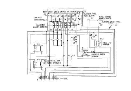
In Fig. 1, the blackout switch panel circuit 100 has
11 panel connector wires, wires 101-111, which connect
directly at lOOa to the harness units o~ any of the
three blackout control system embodiments. There are
six illuminated rocker switches on the blackout switch
panel A as l~ollows: three emergency red light
switches 20, 21 and 22 (alternately re~erred to
hereina~ter as Red 1, Red 2 and Red 3, respectively,
and collectively as Reds); a brake light switch 23;
tail light switch 24; and a sneak light switch 25.
Each rocker switch has a separate light bulb inside
(not shown), and is ~urther illuminated with visible
light emitting diodes or LED's Ll through L6 with
protective resistors Rl through R6 present in each
rocker switch circuit. The blackout switch panel A is
illuminated by two panel lights 50 located on the
sides o~ the panel. Red light switches 20, 21 and 22
are directly connected to panel connector wires 101,
102 and 103, respectively, of panel connector bus bar
lOOA. Switches 23-25 are called blackout switches.
Switches 20-24 on the blackout switch panel A are
single pole, single throw and on-o~f sel~-illuminating
switches. Switch 25 iS a single pole, double throw,
and an on-o~-on self-illuminating switch which
selectively opens the contact, in the "o~ position"
oi~ the switch, and closes the contact to connect the
positive voltage from the battery (Fig. 2)
therethrough in the 'lon position" o~ the switch. The
illumination o:E the rocker switches 23-25 is decreased
CA 0222~l79 l997-l2-l9
W O 97/02156 PCTrUS95/08638
in the evening by the insertion of corresponding
resistors R8, R9 and R10 in the circuit going to the
ground wire 106. Relays R101 and R102 permit one-
switch operation by any o~ Reds 1-3 (20, 21 and 22).
These relays are powered by the vehicle battery
through wire 109. The illuminated rocker switches 20-
25 are isolated by diodes D1 through D6, respectively.
Panel lights override relay R103 permits the cessation
of power to two panel lights 50. Diodes D8 and D9
prevent power feedback to the adjoining circuits.
Panel lighting dimmer switch 27 permits the manual
adjustable ~l mmi ng o~ panel lights 50 during the
evening hours. When blackout switches 23 and 24 are
engaged, panel lights 50 are not illuminated due to
the panel lights override relay R103 being m~nl]~1ly
operated by switches 23 and 24 to prevent panel lights
50 ~rom illuminating. In this circuit, when any o~
the three emergency red light switches 20-22 are
turned on, the current to the other three rem~lnlng
blackout switches 23-25 is turned o~ until the red
light switches are deactivated and the blackout panel
momentary reset button 26 is activated or pressed
down. This resetting ~unction is accomplished by the
dual coil latching of the blackout switch override
relay R104. For example, Red 20 is engaged and
supplies a current through its back~eed diode D1
(which prevents power ~rom Reds 21 and 22 ~rom ~urther
energizing the circuitry o~ Red 20), to the blackout
switch override relay R104, thus opening the contacts
which supply power to the blackout switches. When the
operator wishes to reactivate the blackout switches
23-25, the operator will push the reset button 26 to
activate the opposite coil o~ the dual coil override
relay R104, thus closing the contacts supplying
current to switches 23-25. The reduction in the light
intensity o~ blackout switch panel A is accomplished
by the day/night relay R305 (Fig. 3) which removes the
ground (panel circuit line 105) to the illuminated
CA 0222~179 1997-12-19
W O 97/021S6 PCTrUS95/08638
rocker switches and LED's, thus forcing the rocker
switches and LED's to receive grounding through
resistors R8, R9 and R10. By calibration of resistor
R8 with the LED and the bulb located inside the rocker
switch 23, an acceptable reduction in blackout switch
illumination is achieved. If the officer forgets to
turn off the blackout switches, not using any of the
emergency light switch arrangements, the lights in the
switches will come on to full intensity once the
headlights are turned off, thus alerting the officer
that the blackout switches are still operative. This
is accomplished by the reinstatement of the ground at
the day~night relay R305 leading to the panel circuit
line 105. The power to activate the day/night relay
R305 comes from the running lights switch wire 5A of
the taillights 5 in Fig. 2.
The rocker switches for Reds 1-3 are labeled as
such, but are also visually identified readily by
colored LED~s positioned above the switches in the
blackout panel A, i.e., Red 1 is red, Red 2 is yellow
and Red 3 is green. These colors can be interchanged.
Red 1 is used for pursuing another vehicle with all
the lights on and flashing, i.e., headlights, red
grill lights, rear brake, and backup lights. The red
rear brake lights and white backup lights have an up
and down flash pattern with both brake lights on while
both backup lights are off, alternating with backup
lights on while the brake lights are off. During this
operation the interior dome light is deactivated for
an officer's safety as mentioned earlier. Red 1
connects all the red's light switches together for a
one-switch operation. Red 2 is utilized after the
pursued vehicle has been pulled over with only the
flashing red grill lights, rear brake lights and
backup lights on. Red 3 is used only for rear
lighting of flashing brake and backup lights with the
same flashing pattern as with Red 1. With optional
switch S301 in Fig. 3 closed, power is allowed to pass
CA 0222~l79 l997-l2-l9
W O 97/02156 PCTrUS95/08638
11
through diode D305 and switch S301 to activate the
dome light relay R303, thus preventing the dome light
from being activated with any of the red emergency
lights engaged.
Brake blackout switch 23 cuts out brake, backup and
dome lights. Tail lights' switch 24 cuts out or
deactivates tail or running lights (parking and tail)
and dashboard lighting which includes the lighting of
the digital radio and heater displays. The sneak
light switch 25 controls two sneak lights on the front
of the vehicle (separate from the high and low beam
headlights) which have hoods and are directed
downward. This switch is a two-position switch for
high and low sneak light operation. When the switch
is in the upward position, the LED light is bright,
and in the downward position, the LED is dim. In the
upward position, full power is supplied to the
backfeed diode D7 directly to the LED L6, whereas in
the downward position, the resistor R7 limits the
power or current going to the LED L6 for low sneak
light operation.
Another improvement is the provision for the non-
illumination of the right low beam headlight during a
surveillance of a suspect. The sneak light rocker
switch 25 in the low (dim) sneak light position
energizes the right low beam light cutout relay R308
(Fig. 3) to terminate power through the circuit of
pins 311 and 312, thereby blacking out the right low
beam headlight 53 as illustrated in Fig. 2.
The Fig. 2 wiring harness 200 is designed to be
installed with the vehicle's present wiring harness
between the blackout switch panel circuit 100 of Fig.
1 and the control unit 300 of Fig. 3 Note that panel
connector wires 101 through 111 of the panel connector
bus bar lOOA in Fig. 1 are continued into Fig. 2 as
lOOB. The wiring harness 200 is attached at one end
to various parts of the electrical lighting system of
the vehicle, and at the opposite end to a wire socket
CA 0222~179 1997-12-19
W O 97/02156 PCT/u~9a~
12
and pin connector unit 20OA having wire sockets and
pins 201-228. The power from the battery is
transmitted to the illuminated switch panel A through
an in-line fuse 250. A ground line is also connected
to socket connector wire 209 and to the switch panel
A through panel connector wire 106.
More specifically, as shown in Fig. 2, the harness
unit 200 includes connections to the illuminated
blackout switch panel A which allows a user to
perform the followiny operations: (1) Turn on all the
emergency red lights of the vehicle through the use of
rocker switches Reds 1-3. (2) Since the Fig. 2
harness is designed with neither emergency red lights
nor headlight wig-wagging flashers, the officer will
use Reds 1-3 to supply current to the existing
emergency lighting system on the patrol car. (3) Cut
out the rear window brake light 2, the backup lights
3, the rear brake lights 4, and interior dome light 7
through the use of rocker switch 23. (4) Cut out the
headlight sentinel control 1, the taillights 5 or
running lights, the dashboard lights 6, radio display
lighting 8, and the heater display lighting 9 through
the use of rocker switch 24. (5) Turn on only one of
the two sneak lights 51 or 52 located in the front of
the vehicle through the use of switch 25 in the high
or low position. The sneak light 51 or 52
purposefully produces less light than the headlights,
and is aimed down at the road at a greater angle than
the conventional headlights so as to provide only
enough light for the driver to see directly in front
of him a predetermined minimum distance while
travelling. As mentioned above, sneak light switch 25
in the low position will provide a uni~ue addition in
the cutting or non-illumination of the right low beam
headlight 53 while the other headlight is left
illuminated for a return trip to view the suspects
through the use of the cutout relay R308 of Fig. 3 and
harness connector wires 211 and 212.
CA 0222~l79 l997-l2-l9
W O 97/02156 PCTrUS95/08638
13
As shown in Fig. 2, the wire socket connector unit
200A has 28 pin connections, i.e., 201-228, wherein
panel connector wires 201-205 are directly connected
to corresponding numbered pin connections 101-105 in
Fig. 1. Note that wires from pins 101-103 also are
connected to the emergency lights' wiring which are
present in the vehicle. Pins 201-203 are connected to
the lines providing power to the police vehicle's
emergency lights or Reds 1, 2 and 3. Upon activation
10 o~ any oE the red lights' switches 20, 21 and 22,
power is supplied to the respective pins 201-203.
Wire 106 is connected to pin 209 which is connected to
ground. Wire 107 is connected to pin 206. Wire 108
is connected to pin 208. Wire 109 is connected to pin
15 210 and to the vehicle's battery with an in-line i~use
250. Wires 110 and 111 are connected to the sneak
lights 51 and 52, and wire 111 is also connected to
pin 207.
The wires leading to the various ~ollowing vehicle
20 elements are existing wires. The wire supplying power
to the vehicle's headlight sentinel control 1 is cut,
and the wire lA is connected to pin 226 with the wire
lB connected to pin 225. The wire supplying power to
the vehicle's rear window brake light 2 is cut, and
25 the wire 2A is connected to pin 228 with wire 2B
connected to pin 227. The wire coming :Erom the backup
switch and leading to the backup lights 3 is cut, and
wire 3A coming from the backup lights 3 is connected
to pin 220, while wire 3B going to the backup lights
30 3 is connected to pin 219. The wire supplying power
~rom the brake lights 4 is cut, and wire 4A supplying
the power ~rom the brake lights' switch 23 is
connected to pin 222 while the wire 4B leading to the
brake lights is connected to pin 221. The wire o:E the
35 vehicle leading ~rom the running light switch to the
tail lights 5 is cut, the wire 5A being connected to
pin 224, and the wire 5B being connected to pin 223.
The wire coming ~rom the dashboard dimmer light 6 is
CA 0222~l79 l997-l2-l9
W O 97/02156 PCTrUS9S/08638
14
cut, the wire 6A being connected to pin 214 with the
wire 6B being connected to pin 213. The wire coming
from the interior dome light 7 which is controlled by
the door switch (not shown) is cut. The wire 7A
coming from the interior dome light power is connected
to pin 218. The wire 7B going to the interior dome
light 7 iS connected to pin 217. The wire from the
radio's ( 8) digital display is cut, and the wire 8A
leading from the radio digital display is connected to
pin 215. The wire 8B is connected to pin 216. The
wire from pin 215 leading to the heater's (9) display
is cut, and wire 9b is connected to pin 216. Wire 8A
of the radio display 8 and wire 9A of the heater
display 9 are joined and connected to pin 215.
15 Similarly, wires 8B and 9B are connected by pin 216 to
the running light switch, and lead to the bright mode
selector switches of the radio digital display and the
heater digital display. When power is supplied to the
bright mode selector switches as the running lights
are turned on, the digital displays are placed in
their nighttime mode of operation. The power received
by wire 8B of the radio display 8 and wire 9B of the
heater display 9 are control signals only, placing the
displays in their nighttime mode, but do not supply
power to the displays. The actual power to light the
digital displays when placed in the nighttime mode
comes from the wire coming ~rom the vehicle's
dashboard dimmer control switch to the display lights
so as to allow the driver to adjust the intensity of
the digital display lights through the use of the
vehicle~s dashboard ~; mm~ control switch. The wire
leading from the headlight switch to the right low
beam headlight 53 is cut, forming wires lOA and lOB
connected to pins 211 and 212, respectively.
Some radio manufacturers do not use the dimmer
control switch to energize the digital display, but
supply power directly from the ignition key switch.
Consequently, when the dimmer switch signal is cut,
CA 0222~l79 l997-l2-l9
W 097/02156 PCTrUS9S/08638
the digital display returns to its daytime bright
illumination mode. In this situation, R31 in Fig. 3
is used to regulate the current to the digital display
lights as seen by the rheostat on the vehicle dimmer
control switch 27 in Fig. 1.
In Fig. 3, the blackout control unit 300 includes a
wire plug connector unit 30OA which connects to the
wire socket connector unit 20OA of the harness 200
wired to the vehicle, so as to provide a connection of
pins 301 through 328 to, respectively, socket pins 201
through 228. In this manner, the blackout control
unit 300 can be removed from the vehicle without
having to disconnect the harness 200 by simply
disconnecting the wire plug connector unit 300A Erom
the wire socket connector unit 20OA. With the wire
plug connector 300A connected to the harness, and all
switches 20 through 25 of the illuminated switch panel
A in the off position, the relay switches of the
blackout control unit 300 form the electrical
connections of the vehicle prior to the installation
of the harness 200.
More specifically, with all o~ the relays of the
blackout control unit 300 deactivated, both of the
normally closed switches of the brake and rear window
brake lights~ blackout relay R301 are closed, thereby
allowing the vehicle brake switch (not shown) to
activate the rear window brake light (since pins 327
and 328 in the control bus bar 300A are connected),
and ~urther allowing the activation of the brake
lights because pins 321 and 322 are connected.
Further, pins 317 and 318 are normally connected
through a switch o~ the interior dome (or courtesy)
light's blackout relay R303 to allow the door switches
to energize the interior dome or courtesy light 7. A
taillight and headlight sentinel blackout relay R307
has two normally closed switches, one switch
connecting pins 325 and 326 which connect wires lA and
lB (Fig. 2) to allow power from the vehicle wire to
CA 0222~l79 l997-l2-l9
W 097/02156 PCTrUS9~/08638
16
reach the tail- light and headlight sentinel relay
R307. The other normally closed switch of the relay
R307 connects pins 323 and 324, thereby allowing the
taillights' ( 5) wire to be activated by the running
5 lights' switch. Further, pins 319 and 320 are
connected through a switch in the backup lights
blackout relay R302, allowing activation of the backup
lights 3. With the blackout control unit 300 attached
to the wiring harness unit 200 as discussed above, the
user can black out certain lighting features of the
vehicle. If the user turned on the taillights'
blackout switch 24, power is supplied to pin 108 which
is connected to pin 208 of wire socket connector unit
20OA. With the blackout override relay R304
deactivated, the switches of relay ~307 open from
their normally closed positions. Thus, the power from
pin 30 8 of wire plug connector unit 30OA goes through
the brake, tail and backup lights' override relay R304
supplying power to the relay coil of the taillight and
headlight sentinel lights~ blackout relay R307. The
pins 323, 324, 325, and 326 originally forming
circuits in relay R307 are thereby disconnected. In
this manner, wires lA and lB (Fig. 2) will be
disconnected, preventing the headlight sentinel 1 wire
from supplying power to the taillight and headlight
sentinel blackout relay R307, and preventing the
daytime headlights from activating. Furthér, the wire
to the taillights 5 is disconnected, since the switch
connecting pins 323 and 324 is opened, thereby
disconnecting pins 223 and 224, which in turn
disconnects wire 5A from wire 5B. Thus, the tail
lights~ blackout switch 24 prevents the taillights,
headlight sentinel lights, and together with the
dimmer-radio relay R306, the digital displays of the
heater 9 and radio 8, and dashboard dimmer 6 lighting
from coming on.
CA 0222~179 1997-12-l9
W O 97/02156 PCTrUS95/08638
17
As illustrated in Figs. 1-3, if the user activates
the brake lights' blackout switch 23, the brake and
interior window brake lights' blackout relay R301, the
backup lights blackout relay R302, and the interior
dome light blackout relay R303 are activated. Power
from pin 107 is supplied to pin 206 and pin 306
through the brake, tail and brake lights' override
relay R304, and is transmitted through diode D301 to
the coil of the interior dome light blackout relay
R303, causing the normally closed switch of relay R303
to open. Simultaneously, power from R304 travels to
the brake lights blackout relay R301 causing the
normally closed switches to open. In this manner, the
brake lights 4 and the interior dome light 7 cannot
come on. R302 disconnects the backup lights by pins
319 and 320 and brake light blackout relay R301,
thereby disconnecting the brake lights 4 by pins 321
and 322 and the rear window brake light 2 by pins 327
and 328.
When the taillight rocker switch 24 is activated,
power is supplied to the dimmer and radio blackout
relay R306, connecting pin 310 to pin 315, thus
directing power to the radio display by line 8A and to
the heater display by line 9A. Once power is supplied
to wire 8A of radio's (8) digital display and wire 9A
o~: the heater's (9) digital display, the respective
displays are placed in their nighttime mode. Note
that power is allowed to flow from the running lights~
switch to the radio and heater lighting arrangements
through the use of diode D30 7. However, the diode
D307 prevents power from flowing to the running
lights' switch in order to prevent the running lights
from being turned on by power coming from pin 310.
As stated, R305 supplies the ground ~or the blackout
switch panel's daytime mode by pin 305. When
energized R305 removes the ground to institute the
nighttime mode for reducing the lighting for the
blackout switches 23-25 and LED'S L4-L6 lighting
CA 0222~179 1997-12-19
W O 97/02156 PcT/u~5~g~8
18
through the presence of resistors R8, R9 and R10 when
the blackout switches are used.
The blackout control system of the present invention
is intended to be used in emergency vehicles,
especially police s~uad cars. The blackout features
of the ~irst embodiments and the embodiments to follow
render the vehicle less visible to others outside the
vehicle. These blackout features should be used only
by trained professionals who possess the necessary
skill and discretion to use these features safely.
Each switch of the illuminated switch panel A is
illuminated when activated in order to indicate to the
driver that the blackout feature provided by the
switch is being used. If any of the red light
switches, 20-22, i.e., Reds 1, 2 and 3, respectively,
are turned on, power is provided to the relay coil of
the override relay R304 connected to pins 301, 302 and
303 as shown in Fig. 3. Once the brake, tail and
backup override relay R304 is activated, the normally
closed switches thereof open. Therefore, even if one
or all of the emergency switches Reds 1-3 were
activated, they would be overridden, and the relays
R301, R302, R306, and R307 would provide connections
for allowing the lighting features of the car to
operate normally as discussed above.
Fig. 4 illustrates the bypass plug-in unit 400A
which is a bus bar designed to nullify the specific
emergency light circuits and specific blackout light
circuits installed by reconnecting the original
vehicle circuits affected. This plug-in unit is used
to replace blackout control unit 300 which is removed.
This simple replacement can save the police department
an expense in stripping the blackout control system
installed by allowing the harness 200, for example, to
be left in the vehicle for the resale of the vehicle.
Bypass plug-in unit 400A will allow the vehicle to
resume its original lighting condition before harness
200 was installed. Pins 411 and 412 are connected by
CA 0222~179 1997-12-19
W O 97/02156 PCTrUS95/08638
19
a wire reestablishing connections at lOA and lOB of
the right low beam headlight 10, thus returning the
right low beam headlight circuit to its original
condition. This reconnection is performed with the
5 headlight sentinel 1 wire, the rear window brake light
2 wire, the backup lights 3 wire, the brake lights 4
wire, the taillights 5 wire, the dashboard ~l;mmer 6
wire, the dome light 7 wire, the radio 8 wire, and the
heater 9 wire.
Fig. 5 illustrates the wiring harness 500 of the
second embodiment for the blackout control system of
the present invention. The wiring harness 500, like
the wiring harness 200 of the first embodiment, is
connected to wires 101 through 111 of the switch panel
circuit 100; however, the pin connections in the wire
socket connector unit 500A are different. The wiring
harness 500 has 35 pin connections numbered
consecutively from 501 through 535. The wire from the
headlight sentinel control 1 is cut and wires lA and
lB are connected to pins 531 and 530, respectively.
The wire from the rear window brake light 2 is cut and
wires 2A and 2B are connected to pins 534 and 535,
respectively. The wire from the backup lights 3
within the vehicle being cut, wire 3A is connected to
pin 533 oE the wire socket connector unit 500A, and
wire 3B is connected to pin 532. The wire from the
brake lights 4 being cut, wire 4A is connected to pin
507, and wire 4B is connected to 506. The wire from
the tail lights 5 being cut, wire 5A iS connected to
pin 505, and wire 5B is connected to pin 502. The
wire from the interior dome light 7 being cut, wire 7A
is connected to pin 525, and wire 7B is connected to
pin 526. The wires from the radio 8 and heater 9 are
cut, wires 8A and 9A from each element connected to
pin 527, and wires 8B and 9B from each element
connected to pin 528. The wire from the dimmer switch
6 being cut, wire 6A is connected to pin 524, and wire
6B is connected to 523. In addition to the
CA 0222~179 1997-12-19
W O 97/02156 PcT/u~5J~8~3
aforementioned wires of the vehicle, the harness 500
is connected to the high beam headlights of the
vehicle. The wire llA of the high beam headlights 11
leads to a left high beam light 54. A wire 12 is
connected to wire llB to provide power to the right
high beam light 55. The wire llB is cut into three
sections. Section llA is connected to pin 501 and
leads to the high beam headlight switch. Section llB
is connected to pin 529 and activates the right high
beam headlight 55 through line 12. Section llC is
connected to pin 518 and leads to the left high beam
headlight 54. Unlike the first embodiment, the
harness 500 is connected to the red grill lights of
the vehicle located either in front of the grill or in
front of the radiator behind the grill and between the
headlights. The left red grill light 56 is connected
to pin 519, and the right red grill light 57 is
connected to pin 520. The Reds 1-3 are activated
through the use of any of the red lights' switches 20,
21 and 22 by virtue of relays RlO1 and R102 in Fig. 1.
As in the ~irst embodiment with Reds 1-3, the tail-
lights' blackout switch 24 disables the tail, radio,
and heater lights, headlight sentinel control, and
dashboard lights dimmer of the vehicle. Likewise, the
brake blackout switch 23 disables the brake, rear
window brake, backup, and dome lights. The optional
interior dome blackout switch S601 (Fig. 6) when
closed will allow power from Red switches 20, 21 and
22 to pass through the diodes D603, D604 and D606 to
pass through diode D605 through switch S601 to the
interior dome light blackout relay R603 which opens
the circuit to pin 625 and pin 626. The sneak light
switch 25 turns on the sneak lights 51 and 52 in front
of the vehicle.
The wire 10 energizing the right low beam headlight
53 is cut in order to perform a black eye disguise
maneuver, wherein an officer will return to view the
suspect's vehicle with only the left headlight on so
CA 0222~l79 l997-l2-l9
W O 97/02156 PCT/W95~B638
21
as not to alert the suspect that the same vehicle is
returning. The wire 10A of the low beam headlight 10
i8 connected by pin 521 and powers the left low beam
headlight while the loss of power to side 10B of the
right low beam headlight 53 nulli~ies pin 522.
The harness unit 500 also has a flasher unit 550
having flasher 551 connected thereto along with two
fuses 553 and 554. The flasher unit 550 is any
typical flasher unit used in vehicles, such as those
made by Packard Electric. Since the flasher 551 uses
two outputs, model Dominion 743100 can be used. The
positive end of the battery supplies power to the
fuses 553 and 554. The fuse 554 has the same current
level rating as the fuse 553 and is used to supply the
flasher 551. Fuse 353 passes current to the blackout
switches 23-25 and Reds 1-3.
With the blackout switch panel circuit 100 of Fig.
1 combined with the wiring harness of Fig. 5, Red 1
(rocker switch 20) will flash all lights on Red 1, Red
2 and Red 3 with the addition of high beam headlights
54 and 55, Red 2 (21) will flash the red grill lights
56 and 57, and Red 3 (22) will be a spare switch ~or
the officer to add additional lighting.
In Fig. 6, the blackout control unit 600 has a wire
plug connector unit 600A capable of being connected to
the wire socket connector unit 50OA. When the wire
socket connector 500A is plugged into the wire plug
connector 600A, each o~ the pins 501 through 535 o~
the wiring harness 500 is connected to the
corresponding pins 601 through 635 of the wire plug
connector unit 600A. As in the ~irst embodiment, with
all of the relays o~ the and blackout control unit 600
deactivated, the electrical connections of the vehicle
are identical to those prior to the installation o~
the harness 500.
Once the brake blackout switch 23 is activated with
the switches of the blackout override relay R604
closed, allowing power to pass to relays R601, R602
CA 0222~179 1997-12-19
W O 97/02156 PCT~USgS~
22
and to the interior dome light blackout relay R603.
Upon activation o~ relay R603, pins 625 and 626
connecting the wires 7A and 7B, respectively, of the
interior dome light 7 are disconnected, thereby
preventing the dome (or courtesy) light 7 from coming
on. Also, pins 606 and 607 are disconnected ~rom the
brake and rear window brake lights blackout relay
R601, preventing power coming from wire 4A of the
brake switch from being supplied to wire 4B leading to
the brake lights 4. Blackout relay 601 when activated
also disconnects pins 634 and 635 connected to wires
2A and 2B, respectively, of the window brake light 2
to prevent the rear window brake light 2 from coming
on. Power is also supplied to backup lights blackout
relay R602 with blackout override relay R604 closed.
Upon activation of relay R602, pins 632 and 633 which
connect wires 3B and 3A, respectively, of the backup
lights 3 (Fig. 5, pins 532 and 533) are disconnected,
thereby preventing the backup lights 3 from coming on.
When the taillights blackout switch 24 is activated,
power is supplied to the relay coil o~ the dimmer,
radio display and heater control display blackout
relay R606 from pin 614 through the blackout switch
relay R604. Once the relay R606 is activated, current
from pin 612 is connected to pin 627, directing power
to wires 8A and 9A (Fig. 5), whereby both radio and
heater control displays are placed in their nighttime
mode. Note that power is allowed to ~low ~rom the
running lights' switch to the radio and heater
lighting arrangments through the use of diode D607.
However, the diode D607 prevents power ~rom flowing to
the vehicle's running lights' switch in order to
prevent the running lights from being turned on by
power coming ~rom pin 612.
Also, when the taillights blackout switch 24 is
activated, power is supplied to the relay coil of the
taillights and the headlight sentinel blackout switch
relay R607. When the relay R607 is activated, pins
CA 0222~179 1997-12-19
W O 97/02156 PCTrUS95/08638
23
630 and 631 are disconnected, thereby disconnecting
wires lA and lB so as to prevent power from the
vehicle from powering the headlight sentinel control
module. Further pins 602 and 605 are disconnected so
as to disconnect wires 5A and 5B of the taillights
switch 5, thereby preventing power from reaching the
vehicle running lights.
The power supplied to pin 611 is used to activate
the relay coils of the brake, tail and backup lights
override relay R604 and the Reds' flasher relay R609.
With the blackout override relay R604 activated, the
blackout relays R601 (brake and rear window brake
lights), R602 (backup lights), R606 (dimmer, radio
display and heater display), and R607 (taillights and
headlights sentinel control module) cannot be
activated (the interior dome light 7, could be
activated by pin 609 i~ switch S601 is open), or R601,
R602, R606 and R607 are deactivated if they have
already been activated. In this manner, the brake
lights, backup lights, and taillights function
normally.
In Fig. 5, flasher 551 has an output 551R connected
to pin 504 and an output 551L connected to pin 503.
The outputs 551R and 551L alternately share the power
supplied by the input 551P of the flasher 551. In
this manner, power is supplied to pin 503 half of the
time and to pin 504 the other half of the time. With
relays R611 (high beam headlight flasher relay) and
R609 (Reds flasher relay) activated, the le~t high
beam headlight 54 is controlled by the flasher 551.
The right red grill light 57 is also controlled by the
flasher 551. The right high beam headlight 55 and the
left red grill light 56 are controlled by the flasher
551. In this manner, the right red grill light 57 and
the right high beam headlight 55 alternately flash as
do the left red grill light 56 and the left high beam
headlight 54. A conventional wigwag effect of the
lights is produced, since the right red grill light 57
CA 0222~l79 l997-l2-l9
W O 97/02156 PCT/U~31 r-~
24
and the left high beam headlight 54 are on at the same
time and alternate with the le~t red grill light 56
and the right high beam headlight 55 on at the same
time.
When a police department uses smaller unmarked
vehicles than the large marked squad cars, red grill
lights cannot be placed on the small vehicles due to
limited space between the headlights. Therefore, the
turn signal lights are utilized in place of the red
grill lights to enable the wigwag ~lashing o~ the high
beam headlights with the turn signal lights.
The blackout control unit 600 o~ Fig. 6 includes a
high beam headlight override relay R610 for preventing
the power ~rom the Red 1 lights' switch 20 from
reaching the relay coil of the high beam headlight
flasher relay R611. With the relay R611 maintained in
its deactivated state, pin 601 is connected to pins
618 and 629, leading to the le~t high beam headlight
54 and the right high beam headlight 55, respectively.
Thus, the high beam headlight switch of the vehicle
operates the high beam headlights in the normal
~ashion. Note, that the Reds' ~lasher relay R609 may
still be energized, allowing the ~lasher 551 to
alternately flash the left and right red grill lights
even with the high beam headlight override relay R610
activated. It=should be noted that the red grill
lights can be positioned either behind or in ~ront of
the emergency vehicle's front grill, i.e., proximate
to the grill, and between the headlights.
The high beam headlight override relay R610 is
activated by the high beam headlight switch through
power supplied thereby to pin 501, leading to pin 601,
and leading to diode D608 which allows power to pass
from pin 601 to the relay coil of the high beam
headlight override relay R610. The relay R610 is also
activated by a nighttime high beam headlight override
switch S602 which, when activated, supplies power
normally going to the switch from wire 5A of the tail
CA 0222~179 1997-12-19
W O 97/02156 PCT/U,'J,~_"'~6
lights 5 (Fig. 5) to pin 505, allowing the power
coming from pin 605 of the wire plug connector unit
600A to pass through slide switch 602 (switch for the
nighttime high beam headlight flasher override)
through diode D609 to the coil of the relay R610 (high
beam headlight override), thereby disabling the relay
R611 (high beam headlight flasher).
If the officer forgets to turn o~f the blackout
rocker switches of the blackout switch panel A, not
using any of the emergency switch arrangements, the
lights in the rocker switches will come on to full
intensity once the headlights are turned off, thus
alerting the officer to the blackout switch operation.
This warning is accomplished by the deactivated mode
or grounding of the pin 610 of the day and night
relay R605 supplying grounding to blackout switches
23, 24 and 25 by the switch panel circuit (100) pin
105 (Fig. 1). The day and night relay R605 is
activated by the vehicle running lights' switch
connected to the tail lights 5. Relay R605 also
supplies a ground going through the panel lights
override relay R103 (Fig. 1) to supply ground for the
illuminating panel lights 50 when activated.
Switch S601 when on supplies power to the interior
dome light relay R603 to prevent the dome light ~rom
coming on when any o~ the emergency lights are on.
Activation o~ the Reds flasher relay R609 by pin 611
supplies power through diode D604 to diode D605 (but
not through diodes D603 and D606) and switch S601 when
on (but not through diodes D601 and D602) to prevent
~eedback to the blackout relays R601 (brake and rear
window brake lights) and R602 (backup lights).
Fig. 7 illustrates the bypass plug-in unit 700A
which replaces blackout control unit 600. The
replacement procedure is similar to that described
earlier for installing bypass plug-in unit 400A.
A third embodiment for the blackout control system
of the present invention is illustrated in Fig. 8
CA 0222~179 1997-12-19
W O 97/02156 PCT/U'~3,'~ 8
26
(harness unit 800) and Fig 9 (control unit 900). The
third embodiment is similar to the second embodiment
of Figs. 5 and 6. However, the third embodiment
includes a ~lasher arrangement for the backup lights
and brake lights. As shown in Fig. 8, the wiring
harness 800 has a wire socket connector unit 80OA
attached at one end thereof, and is connected to the
control unit 900 and the electrical lighting system of
the vehicle at the other end. Like the wiring harness
500 of the second embodiment, the wiring harness unit
800 is connected to wires 101 through 111 of the
blackout switch panel unit 100 of the vehicle. The
vehicle wires are cut as described in the second
=embodiment above, and the cut wires are connected to
their corresponding pins as follows: lA and lB
(headlight sentinel) to 828 and 827, respectively; 2A
and 2b (rear window brake light) to 837 and 836; 3A
and 3B (backup lighl_s) to 809 and 808; 4A and 4B
(brake lights) to 834 and 833; 5A and 5B (taillights)
to 810 and 811; 6A and 6B (dashboard dimmer) to 830
and 829; 7A and 7B (interior dome light) to 826 and
818; 8A and 9A (display lights of the digital radio
and heater, respectively) to 831; 8B and 9B to 835;
lOA (right low beam headlight) to 824; and lOB (right
low beam headlight) to 825.
In the third embodiment of the wiring harness unit
800 shown in Fig. 8, the wire connecting the backup
lights 3 is cut to produce wires 3A and 3B. Wire 3A
goes to pin 809 and wire 3B is connected to pin 808.
With the additional individual connections of the
wiring harness 800 to the right and left backup lights
3 and the right and left brake lights 4, a flashing
effect of the backup and brake lights is achieved.
This is accomplished by using a conventional flasher
unit 850. The flasher unit 850 uses conventional
flasher 851 and 852, both o~ which may be model
Dominion 743100 since they each have two outputs. The
flasher unit 850 has two fuses 853 and 854. Fuse 854
CA 0222~179 1997-12-19
W O 97/02156 PCTrUS95/08638
27
has the same amperage rating as fuse 853, and ~use 854
is used to power the flashers 851 and 852 of the
flasher unit 850 under the control of the illuminated
switch panel A discussed below. Fuse 8S3 controls the
blackout relays of the blackout controller 900 as
discussed below.
As shown in Fig. 9, the blackout control unit 900
has similar blackout features as blackout control unit
600. More specifically, the power to the taillights
and headlight sentinel control module is controlled by
the tail and headlight sentinel blackout relay R907.
Relay R907 normally provides a connection between the
tail- lights (or the vehicle's running lights switch)
and said lights through a normally closed switch R907
connecting pins 910 and 911. The relay R907 also
normally provides a connection for the headlight
sentinel control through a normally closed switch
connecting pins 927 and 928. The brake and backup
lights' ~lasher relay R912 is used to power the
flasher 852 by pin connection 903 leading to the
output 852L of the flasher 852 and pin connection 904
leading to the output 852R of the ~lasher 852.
Further, the brake and rear window brake light
blackout relay R901 and the interior dome lights'
relay R903 and backup lights blackout relay R902 are
used to black out the rear window brake lights 2, the
backup lights 3, the brake lights 4, and the interior
dome light 7, upon the activation o~ the brake
blackout switch 23 connected to pins 815 and 915. The
power is transmitted through the brake, tail and
backup lights' override relay R904 to the relays R901,
R902 and R903. Diodes D910 and D911 are positioned in
the lines coming from pins 937 and 934, respectively,
to the normally closed relay R901 in order to prevent
feedback from the rear flashing lights (brake and rear
window brake) from affecting the vehicle's modular
computer. Power supplied to pin 916 activates the
relay R906 so as to interrupt the connection made
CA 0222~179 1997-12-19
W O 97/02156 PCT~US9~/08638
28
between pins 929 and 930, which disconnects wire 6A
supplying power ~rom the dimmer switch to wire 6B
leading to the dashboard dimmer and the radio lights.
The power from pin 912 leading to R906 diverts power
through pin 931 to wires 8A and 9A (Fig. 8) to place
the digital displays o~ the radio and heater control
displays in their nighttime mode o~ operation as
discussed with the other embodiments above. A diode
D907 allows power ~rom wires 8B (radio display) and 9B
(heater display) coming ~rom the vehicle's running
light switch to go to wires 8A and 9A, while
preventing the power supplied to wires 8A and 9A ~rom
being ~ed into the running light switch by 8B and 9B
which would turn the running lights on. Note that a
brake, tail and backup lights' override relay R904,
deactivates the blackout ~eatures o~ the blackout
control unit 900 in the same m~nne~ as R604 discussed
above.
The flasher ~eatures o~ the blackout control unit
900 are similar to those o~ blackout control unit 600.
Relay R909 (Reds ~lasher relay) connects the red grill
lights 56 and 57 to the flasher unit 850 when
activated in the same manner as R609 (Reds ~lasher) o~
the control unit 600 connects the red grill lights 56
and 57 to the ~lasher unit 550 It should be noted
that the existing turn signal lights are substituted
for the red grill lights ~or the smaller unmarked
vehicles (not shown). Relay R911 connects the high
beam headlights 54 and 55 to the ~lasher unit 850 in
the same manner as R611 of the control unit 600
connects the high beam headlights 54 and 55 to the
~lasher unit 550 when activated.
Each ~lasher 851 and 852 has one input ~or power and
two outputs. Flasher 850 is connected to the power
~rom ~use 854 via input 851P, and ~lasher 852 is
connected to the power ~rom ~use 854 via input 852P.
Flasher outputs 851L, 851R, 852L, and 852R are
connected to pins 806, 805, 803, and 804,
CA 0222~179 1997-12-19
W O 97/02156 PCT~US~5~'~9~38
29
respectively. As shown in Fig. 8, these pins lead to
open connections to the various relays controlling the
flashing features. Thus, the flashers 851 and 852 are
not activated, since they are not connected to lights.
With the activation of the Red 1 switch 20, power is
supplied to pin 919 of the control unit 900. This
power also activates the relay coil of the blackout
override relay R904 to deactivate the blackout
features of the control unit 900 as discussed above.
Further the high beam headlights flasher relay R911 is
activated through the normally closed switch of the
high beam headlights override relay R910 through pin
919. The brake and backup lights' flasher relay R912
is activated through Reds 1, 2 and Red 3 (20-22, Fig.
1) by pins 919, 913 and 914. The red grill lights'
relay R909 is activated through pin 913. In this
manner, the connection to the left high beam headlight
54 through pin 821 is changed to pin 806 leading to
the output 851L as controlled by relay R911, while the
connection to the right high beam headlight 55 through
pin 832 is changed to pin 805 leading to output 851R.
Likewise, the outputs 851L and 851R are connected to
pins 806 and 805, respectively, through the activation
of the red grill lights relay R909. Pins 922 and 923
lead to the left grill light 56 and the right grill
light 57, respectively. Thus, through the use of
relays R909 and R911, the same wigwag effect of the
high beam headlights 54 and 55 along with the red
grill lights 56 and 57 (or turn signal lights) is
achieved through control unit 900 as is achieved
through control unit 600 described above. Relay R909
when activated, permits the energization of the coil
in blackout override relay R904 by way of diode D904.
When pin 919 is activated by the Red 1 switch (20)
through pin 819, diode D903 permits the energization
of the coil in the brake, tail and backup lights~
override relay R904. The slide switch S902 for the
nighttime flasher override R910, when closed, permits
CA 0222~179 1997-12-19
W O 97/02156 PCT/U~951'~r~8
the override of the high beam headlights ~lashing by
passing the current through diode D909 to relay R910.
When the Red 3 rocker switch 22 is energized, current
~rom pin 914 passes through diode D906 to energize the
coil in the brake and backup lights' ~lasher relay
R912 and the coil in the brake, tail and backup
lights' override relay R904. With slide switch S901
open, relays R901, R902, R903, R906, and R907 are de-
energized when the brake, tail and backup lights'
override relay R904 is energized by activation of
either Red 2 (switch 21) or Red 3 (switch 22).
The high beam override relay R910 overrides the high
beam headlight flasher ~unction upon activation of the
high beam headlight switch supplying current to pin
907, which current passes through the diode D908 and
energizes the coil of the high beam headlights'
override relay R910. Further, the relay R910 may also
be energized upon activation of the vehicle running
lights' switch ~rom pin 810 which supplies power to
pin 910 upon activation of the running lights. Diode
D909 prevents power from the high beam headlight
switch ~rom being ~h~nneled to the running lights, and
diode D908 prevents power ~rom the running lights'
switch from reaching the output of the high beam
headlights~ switch. With the activation of relay
R912, a ~lash pattern is activated with both brake
lights on with both backup lights of~, and then both
backup lights on with both brake lights off. The
relay R912 connects the backup lights to the output
852R by connecting pin 904 to pin 908. The relay R912
also connects the rear brake lights to the output 852L
by connecting pin 903 to pin 933. In this manner, the
backup lights are simultaneously on for hal~ o~ the
time, and the brake lights are simultaneously on ~or
the other hal~ of the time. This produces the
flashing effect for the brake lights and backup
lights.
CA 0222~179 1997-12-19
W O 97/02156 P~T~US95/08638
31
In Fig. 10 the bypass plug-in unit lOOOA connects to
bypass the control unit 900 of Fig. 9, thus restoring
the vehicle to its original lighting condition. These
bypass plug-in units 400A, 700A and lOOOA can be
attached to their respective blackout harness units
200, 500 and 800. The pertinent connections for each
bypass plug unit are labeled. This feature will allow
the officer to bypass the blackout control units for
servicing of the emergency lighting system in a
modified vehicle and return the vehicle back to its
original lighting condition. The use of these bypass
plug-in units can save the police department in
expensive stripping costs for resale.
The blackout control panel system can be
advantageously combined with a siren control head,
i.e., using the siren with the present blackout
lighting.
It is to be understood that the present invention is
not limited to the embodiments described above, but
encompasses any and all embodiments within the scope
of the following claims.