Note: Descriptions are shown in the official language in which they were submitted.
CA 02225409 1997-12-22
WO 97/41764 PCT/IT97/00098
-1 -
"CONTAINER-DISPENSER OF PAPER UPON MANUAL TEARING FROM
A ROLL. PROVIDED WITH ANOTHER ROLL IN RESERVE"
The present invention relates to a container-dispenser
of single
lengths of paper by manual tearing from a continuous paper
web wound
up to form a roll, suitable to include two rolls at a time,
one of which in
reserve.
Paper dispensers are known, in particular of toilet paper
but also for
the use as towels, which are wall-mounted in public places
such as the
rest rooms of motorway snack-bars, railway stations, airports,
restaurants,
etc., where the paper consumption is very high and the
rolls are so
frequently replaced that a very careful control is required
whenever the
paper rolls in reserve are not to be left directly available
to the users for
the replacement, with the consequence of unavoidable waste
of material.
In order to reduce the interventions of the personnel charged
with the
replacement, sometimes dispensers of toilet paper or towels
have been
adopted which are suitable to contain a pair of paper rolls,
one of which in
reserve, in such a way that a better store is available
between one
replacement and another. Usually in these known devices
the two rolls are
in turn accessible from the outside and it is the same
user that displaces a
slidable shutter, when a roll is finished, to make it possible
to have access
to the other. Of course there is no hindrance, however,
that the user may
take paper, no matter whether from one of the other roll
by simply moving
the shutter, until a possible suitable situation takes
place in which both the
rolls are partially exhausted and the person who has to
carry out the
replacement must choose between leaving the things as they
are, with the
risk that before a subsequent intervention al! the paper
is taken away from
both the rolls, or carrying out an early replacement with
unavoidable waste
of material.
In order to avoid doubtful situations of this type, in
which both the
solutions would be disadvantageous, it has now been conceived,
being
the object of the present invention, a device for dispensing
paper lengths
from a roll, which is adapted to contain two paper rolls
at a time, wherein
the withdrawal is automatically ensured from the same preferential
side.
Thereafter the other side becomes accessible and the withdrawal
can then
CA 02225409 1997-12-22
WO 97/41764 PCT/IT97/00098
-2-
be pertormed from the second roll in reserve, preferably until a fresh roll is
inserted in the preferential exhausted side.
This main object of the present invention is obtained by means of a
container-dispensing device being provided with the features of claim 1.
According to other particular aspects of the present invention, the
inside of the device is inaccessible by the user during its normal operation
and the relevant cover is fixed to the rear wall of the device itself by means
of a central stiffening member having also the function of ashtray.
These and other objects, advantages and features of the device
according to the present invention will appear clearer from the following
detailed description of the preferred embodiment thereof, given by way of
non-limiting example with reference to the annexed drawings in which:
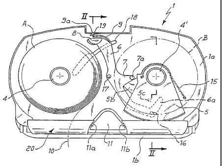
FIGURE 1 shows a schematic, front view of the device according to
the invention with cover removed and in a situation preceding its
functioning, wherein two fresh rolls have been just placed or at least only
one in the seat of normal dispensing (on the left-hand);
FIGURE 2 shows a sectional view along the fine ll-t! of Fig. 1,
wherein the cover has been considered closed and an upper stiffening and
blocking member is near its lowered position;
FIGURE 3 shows a view similar to that of Fig. 1, in which the
preliminary step of loading the device is over and its normal working can
start;
FIGURE 4 shows again a view similar to those of Figs. 1 and 3, in a
situation of complete exhaustion of the roll of normal dispensing;
FIGURE 5 shows again a similar view in a situation immediately
subsequent to that of Fig. 4, wherein the roil in reserve (on the right side)
is accessible to the users;
FIGURE 6 shows, again in the same view, a situation in which the
paper withdrawal newly occurs on the left-hand side where the roll
originally on the right has been displaced, while a fresh roll in reserve has
been placed on the right-hand side; and
FIGURE 7 shows a situation in preparation to the one of Fig. 1 or '
however preliminary to the replacement of a roll in the left seat.
With reference to the drawings, the device has an external housing '
formed of a stationary portion 1 comprising a rear wall 1a, integral with a
peripheral lip 1 b and provided with wall fastening means, as well as a front
CA 02225409 1997-12-22
WO 97/41764 PCT/IT97/00098
-3-
covering (id 2 pivotedly mounted at 12 in its lower side
to the stationary
portion 1. A member 3 i~ pivotedly mounfed on tie upper
side of the cover
2, and adapted to fit in a hollow seat formed in the cover
itself and in the
upper portion of the wall 1, thus mutually coupling these
two portions and
stiffening the assembly. Preferably member 3 is shaped with
such a hollow
to make it have the shape and the functions of an ashtray.
Two cylindrical pins 4, 4', substantially parallel to each
other,
protrude outwards from the rear wall, possibly formed integrally
with the
wall itself by moulding, which are adapted to provide the
unwinding
support for two paper rolls, A and B respectively, being
housed within the
container formed of said stationary wall 7 and cover 2,
when closed. The
lower portion of the lip 1 b has two openings or elongated
through holes 20
which extend parallel to the two pins 4, 4' in a substantially
underlying
zone, corresponding to the same pins. Through said openings
the tree end
of paper 10 coming from the respective roll A or B is caused
to be
accessible from the outside to be withdrawn and torn off
by the user in the
desired length. Furthermore, still in the lower zone of
the container,
centrally between the two passages 20 there is preferably
provided a
chamber 11 substantially shaped as a rounded triangle for
dividing the
inner space of the container in two seats, right- and left-hand,
associated
to the two rolls A, B. This chamber 11 is hollow and accessible
at its
inside, with cover 2 open, with the possibility of housing
a deodorizing pill,
preferably supplied in a net-type container (not shown)
of triangular shape,
homologous to that of the chamber 11, in which it can be
placed by means
of guides 11 a and 11 b far releasing deodorizing vapours
in the
environment.
More in particular, according to the present invention,
on one of the
two pins 4, 4', namely the left one as shown in the drawings,
there is
mounted freely rotatable as a ring a member 5 having a shape
of sector of
a circle, whose peripheral edge is shaped as an arc of circle
and extends
frontly for a length sufficient to obstruct, except than
in the position of Fig.
5, the corresponding underlying hole 20 communicating to
the outside.
This sector 5 is prevented from moving along the pin 4'
by a positioning
and blocking cap or plug 14 being fitted from the outside
onto the pin itself
and adapted to keep the sector 5 in a position nearer the
rear or back wall
1 a. Of course the thickness of sector 5 and of the cap
14 are such as to
CA 02225409 1997-12-22
WO 97!41764 PCT/IT97I00098
-4-
allow in any case the insertion of roll B with its core, while the vertical
wall
of sector 5 is sufficiently near to the back wall 1 a not to cause any
hindrance in the axial direction, whereby the paper roll is entirely
comprised within the container with cover 2 closed and the distance of the
protruding peripheral flange 5a from the axis of pin 4' cannot cause
obstacles in the radial direction, thus allowing the roll to be housed without
problems. A spring 15 is fixed under tension at an end to the sector 5 and
at the other end to the back 1 a of the device to normally bias the sector 5
to the position of Fig. 5 in which the lower opening 20 communicates the
outside with the roll B.
!n the other working situations, the sector 5 is instead always kept in
the position at which the opening 20 is obstructed through the engagement
of the fever 6 with a cam-shaped side portion 5b thereof. The active profile
of the latter corresponds, when the sector 5 is in the intercepting vertical
position, to an arc of circle having the center at a point 16 which is
coincident with the fulcrum of lever 6. At the end of a shaped dependent
portion 7 with a Lower profile corresponding to that of cam portion 5b, the
lever 6 is provided with a member for engagement with said cam,
preferably a roller 7a, to hold the sector 5 in the intercepting vertical
position against the bias of spring 15 as long as sector 5 and lever 6 are in
contact, in other words there is contact between cam 5b and roller 7a.
It will be appreciated that fulcrum 16 is placed near the lower end of
lever 6 and this latter extends in a plane behind sector 5, as is shown in
the embodiment of Fig. 2, being provided at the opposite end with a
contact member 8, preferably of rounded thumb-shape, capable of resting
by gravity onto the roll A which is mounted on the left pin 4, where there is
no intercepting sector 5. Such a thumb 8 is preferably formed, not
integrally with lever 6, of two members of different thickness being fixed
side by side, and can be fitted at the end opposite to the fulcrum 16 in two
alternative orientations, thus being directed towards the contact surface
with two different thicknesses according to the core size of the roll in use.
Therefore, when adopting rolls with a core of greater diameter, the "
contacting end 8 of lever 6 will be fixed in such a way to come into contact
with the core in correspondence with the same angle formed by lever 6
about fulcrum 16 (Fig. 4) as with a core of smaller diameter, whereby it will
be the portion of thumb 8 with lower thickness to come into contact with
CA 02225409 1997-12-22
WO 97141764 PCT/IT97/00098
_5_
roll A, while the orientation will be opposite when rolls
are used with a
lesser diameter size of the core, in order to have contact
with the thicker
portion of a thumb.
According to a preferred embodiment of the device of the
invention,
the upper end of fever 6, formed downwards with the follower
thumb
member 8, bifurcates upwardly with a flexible tang member
9 provided with
a tooth 9a protruding upwards and adapted to fit in a corresponding
slot 19
formed in the upper portion of the frontally projecting
lip 1 b, thus being
able to fit in such a slot and hold the lever in the raised
position as
represented in Fig. 1. Such a slot 19 is preferably formed
in the hollow
area provided as seat of the blocking and stiffening member
3 with
possible functions of ashtray. This latter in turn has a
pin 13 (Fig. 2)
directed downwards, adapted to fit in said slot 19 to close
and kept
blocked in position the cover 2 on which the member 3 is
pivotedly
mounted. On the other hand, if in the slot 19 the tooth
9a of lever 6 has
been already inserted from underneath, the entry of pin
13 from above
would cause its ejection, thus consequently releasing the
lever which,
rotating around the pivot 16 by gravity, would stop at the
position in which,
according to the active thickness chosen at the moment of
fitting the thumb
on the lever, such a thumb touches the surface of the left
roll A.
The lever 6 is also formed, at a nearly middle length, with
a pawl 17
directed to the outside and adapted to engage the flange
5a of sector 5
when this is positioned as in Fig. 5, while there is preferably
provided a
guide 18 for the lever 6, as required by the flexibility
of the latter due to its
relative length, thus avoiding possible oscillations during
the movement of
the lever itself.
It will be finally appreciated that lever 6, at the end
at which it is
pivoted in 16, preferably is formed with a tail portion
6a facing upwards
and adapted to come into engagement, when the left roll
A is completely
empty, with a pawl 5c integral with the rear portion of
sector 5.
It clearly appears from the foregoing that the device according
to the
invention has one side for housing a roll in reserve and
another side for
housing the roll from which the paper is normally withdrawn.
The "reserve"
side is that on which the intercepting sector 5 is mounted,
which in the
illustrated case has been considered on the right side,
but of course the
relative positions could be inverted.
CA 02225409 1997-12-22
WO 97/41764 PCT/IT97/00098
_g_
The device operation will now be better explained in the following
description. Upon initially charging the device with the two roils A, B, as
represented in Fig. 1, Lever 6 must be brought to the position indicated,
with the tooth 9a in the upper slot 19 in order not to interfere with the
loading of the rolls, in particular the roll A. In order to bring the fever 6
to
this position, action is previously made onto the sector 5 by causing it to
rotate in anticlockwise direction against the tension of spring 5, thus
engaging with its paw( 5c the tai! 6a of lever 6 which, by rotating in
clockwise direction about fulcrum 16, reaches the position as indicated,
then keeping such a position during the paper rolls charging.
Subsequently the cover 2 is closed and blocked onto the stationary portion
1 by lowering member 3, having also an ashtray function, which with its pin
13 fits into the slot 19 and at the same time pushes away therefrom the
tooth 9a, whereby the lever 6 is disengaged and drops by gravity with its
follower thumb 8 onto the surface of roll A. As previously stated, the thumb
8 will have been preliminarly mounted onto the lever 6 in such a way to
present to the contact the portion of greater or lesser thickness depending
on whether the core of the used rolls is respectively of smaller or greater
diameter, since usually two standard sizes are foreseen for such a
diameter. Through the opening 20 on the left side an end portion of paper
10 from the roll A is accessible from the outside and its supply to the users
can start while, on reduction of the diameter in consequence of the roll
unwinding, the follower thumb 8 drops and lever 6 rotates in a
counterclockwise direction about its fulcrum 16, while the roller 7a at the
end of its appendix 7 moves with slightest friction, along the profile of cam
5b of sector 5, thus keeping the latter in the vertical position of Fig. 3
against the tension bias exerted by spring 15. Since the cam 5b profile has
a substantially arc of circle shape, with center in 16, during the lever 6
rotation there is no movement of sector 5 by virtue of lack of any
eccentricity.
Upon complete exhaustion of the roll A (Fig. 4) and the follower
thumb 8 being in contact with the roll core, the roller 7a and cam 5b are no
longer in contact; thereby the spring 15 can exert its tension bias onto the
sector 5 making the same to rotate in clockwise direction unfit a neutral '
position of rest or possibly against a stop (not shown), substantially as
represented in Fig. 5. In this situation the opening 20 on the~right side is
CA 02225409 1997-12-22
WO 97/41764 PCT/IT97100098
-7-
no longer obstructed by the lower flange 5a of the rotatory sector, and
thereby a paper length is made accessible to the outside, being dispensed
a from the roll B in reserve from which the users can then take paper until
the subsequent intervention of the personnel in charge.
This intervention is preferably performed by bringing to the left side
the roll B in reserve, already partially utilized, and inserting on the store
side, the right one, a fresh roll C (or introducing two fresh rolls if the
roll B
is already almost exhausted). ft will be appreciated that in order to mount
the roll B (or a fresh one) on the left side of normal distribution, the fever
6
must be brought again to the initial position of Figs. 1 and 7, whereby the
sector 5 wilt have to be previously brought to the vertical interception
position and, to avoid that this may happen due to a mere inadvertence,
the pawl 17 has been provided, which would abut against the peripheral lip
of the sector itself thus preventing lever 6 from lifting. In this way any
possibility is excluded that both openings 20 may be accessible at the
same time and that the user can choose at which side to take the paper:
the withdrawal should be normally carried out always from the same
preferential side except for the situation in which the roll on this side is
completely empty and therefore the roll in reserve on the other side has
become available, but as soon as the normal situation has been re
established, the stored roll is excluded from possible withdrawals of paper.
As already stated above, auxiliary elements of the device according
to the invention are the ashtray 3 mainly having functions of blocking and
stiffening of the structure, as well as the deodorizing cavity 11 whose
content is accessible from the outside only with open cover.
Possible additions and/or modifications can be brought by those
skilled in the art to the above-described and illustrated embodiment of the
device according to the invention without exceeding from the scope of the
invention itself. In particular different shapes could be adopted for the
sector 5 and lever 6 and possibly provided additional auxiliary elements.
t