Note: Descriptions are shown in the official language in which they were submitted.
CA 0222~80 1997-12-23
BAC~CGROUND OF THE INVENTION
Field of the Invention
The invention relates to percutaneous catheters and more
specifically to anchoring devices to secure percutaneous catheters
at a desired location in a patient~s body.
Descri~tion of Related Art
PerCutaneoUS catheters are commonly used in medical
applications to deliver or remove fluids from a patient~s body.
It is very common in the treatment of patients to utilize
intravenous catheters to introduce certain fluids directly into
the bloodstream of the patients. It is also common to utilize
catheteri ation to bypass blocked passage between organs. For
example, when the passage between a kidney and the bladder is
blocked, accepted treatment can be provided by catheterization of
the kidney to drain urine.
In general, a catheter consists of a soft tube, or
cannula, having an opening, or lumen, extending through the
cannula. Placing a catheter usually involves introducing an
introducer sheath enveloped around a needle, the introducer sheath
having an outside diameter slightly larger than the needle, into
the patient at the desired location, and then removing the needle.
The cathe~er is then introduced into the patient through the
introducer. In the case of an intravenous catheter, the infused
fluid flows directly through the catheter into the vein in which
the cathe-er is introduced. In the case of a urinary drainage
-1- 056301.Po03
CA 0222~80 l997-l2-23
catheter, the urine is drained directly from the kidney to a
dispensary.
In as much as catheters have different uses, catheters
also have different lengths. For intravenous catheters, for
example, there exists several various lengths of catheters
including short intravenous catheters that are placed
peripherally, for example, in the hand, midline catheters that are
fed approximately six to eight inches into a vein, for example,
from the hand to the upper arm where the vein is bigger and better
hemodilution and blood flow is achieved, and central venous
catheters of significant length that may be placed peripherally,
i.e., in the arm, and fed, for example, to the superior vena cava.
Regardless of the length, it is desired to secure the catheter so
that it maintains its position in the body. Catheter positioning
in the patient's body is important, particularly in determining
the concentration and toxicity of fluid added to the body. To
ensure that the catheter maintains its position, the catheter
should be anchored to the exterior body of a patient, and ideally
it should be anchored as closely as possible to the entry site or
junction of the catheter to provide less opportunity for the
catheter to be repositioned.
Common securing devices include tape-down or lock-down
wings fixedly attached to the catheter cannula. The fixed-
location catheter lock-down wings work well if the full length of
the catheter cannula is placed in the patient so that the wings
are secured at the junction. A problem, however, arises when the
decision is made to shorten the placement of the catheter in the
-2- 056301.P003
CA 0222~80 1997-12-23
patient so that excess catheter material separates the lock-down
wings from the introduction site or junction. If the wings are
anchored to the patient at a position that is too far away from
the insertion site, migration or pistoning of the catheter cannula
can occur. One way to get around this is to cut the catheter
cannula to length before insertion of the catheter into the body.
Because most catheters include a hub at their distal end, the only
convenient end to cut away is the introductory end. However,
catheter cannulas are generally constructed with a tapered tip at
the introductory end to make insertion easier, i.e., less
traumatic, to the patient. If the tapered tip is removed, for
example by clipping a section of the catheter away, such patient
considerations are ignored. Further, if the shortened estimate
turns out to be incorrect, the physician or nurse still has excess
catheter cannula material that must be dealt with. Another way to
deal with the excess cannula material that extends from the
junction, whether or not the catheter has been shortened, is to
coil the excess catheter cannula material around the securing
wings before the wings are secured to the patient. This method
allows the securing device to be anchored at the junction, but
creates an awkward and bulkv device.
Adjustable anchor ng devices have been introduced that
allow the device to be positioned at the catheter junction once
the catheter is placed. However, these devices are either bulky
or difficult to effectively install at the junction site. One
adjustable anchoring device is a two-piece device wherein a
flexible first piece with a split ~long its bottom portion fits
_3_ 056301.P003
CA 0222~80 l997-l2-23
over the cannula adjacent to the junction, and a second rigid
piece snaps over the first piece to compress the first piece to
the cannula so that the catheter device cannot move. The entire
apparatus is then sutured or taped to the skin. A problem with
this type of device is that it is a two-piece device that must be
sized and fit on the catheter cannula at the junction. The
placement of the securing device must be done in an artful manner
so as not to disturb the patient or lose the distinct pieces.
Further, the second rigid piece makes the device bulky.
Another type of adjustable anchoring device is
compressing an eyelet, two-piece squeeze fit fastening device.
This device utilizes at least one cylindrical eyelet that fits
around the catheter and inside a two-piece fastening device
mounted on the catheter cannula. When the fastening device is
forced together, the eyelet is compressed to apply frictional
pressure to the catheter. This securing device involves at least
three pieces that may be easily misplaced and it is difficult to
manipulate and install the fastening device at the junction.
What is needed is an adjustable anchoring device that is
easy to install at the junction of a patient and is not bulky or
cumbersome.
_g_ 056301.P003
CA 0222~80 1997-12-23
SUMMARY OF TR~ INVENTION
An adjustable anchoring device to retain a catheter at a
desired location inside a patient is disclosed. The anchoring
device includes a securing member with a tubular body portion and
an opening extending through the tubular body portion. The
opening of the tubular body portion has a first dimension that is
adapted to retain the catheter by frictionally engaging the
catheter. The body portion is also dilatable to form an opening
with a second dimension such that the securing member can slidably
move about the catheter. The anchoring device is intended to
secure any of the various types of catheters, including, but not
limited to, vascular, neurological, and urinar~ drainage
catheters.
A dilator member to dilate the tubular body portion of
the securing member from having an opening with the first
dimension to an opening with the larger second dimension is also
disclosed. The dilator member includes a forward end that is
adapted to detachably mate with the securing member through a
portion of the opening of the securing member. The mating dilates
the body portion of the securing member from an opening with the
first dimension to an opening with the second dimension. In the
mated position, the dilator member and the securing member are
adapted to slidably move about the catheter to easily position the
catheter at the desired location, e.g., the junction.
-5- 056301.Poo~
CA 02225580 1997-12-23
Additional features and benefits of the invention will
become apparent from the detailed description, figures, and claims
set forth below.
-6- 056301.Po03
CA 0222~80 l997-l2-23
BRIEF D~SCRIPTION OF T~ DRAWINGS
Figure 1 is a planar side view of an intravenous
catheter in place in the arm of a patient wherein the intravenous
catheter is secured by the anchoring device of the invention.
Figure 2 is a planar top view of the anchoring device
of the invention used to secure an intravenous catheter in a
patient.
Figure 3 is a perspective side view of the anchoring
device of the invention securing a catheter.
Figure 4 is a perspective side view of the anchoring
device of the invention including a securing member that is
dilated by a dilator member to be slidably movable about the
catheter.
Figure 5 is a planar top view of the anchoring device
of the invention taken through line A-A of Figure 4 wherein the
securing member is dilated by a dilator member to be slidably
movable about the catheter.
Figure ~ illustrates a perspective side view of the
dilator member portion of the anchoring device of the invention.
20Figure 7 is a cross-sectional side view of the
anchoring device cf the invention taken through line 3-B of Figure
5.
Figures 8 and 9 illustrate the method of removal of the
dilator member from the securing member. Figure 8 illustrates
that the dilator member is separated from the securing member.
_7_ 056301.P003
CA 0222~80 l997-l2-23
Figure 9 illustrates that the dilator member is broken and
removed from the catheter.
Figure 10 is a planar top view of a securing member of
the anchoring device of the invention wherein the securing member
has a tubular body portion that is curved.
Flgure 11 is a planar top view of a securing member of
the anchoring device of the invention wherein the securing member
has a tubular body portion that is a complete curve or "U".
Figure 12 is a perspective side view of a securing
member of the anchoring device of the invention wherein the
securing member includes a pair of annularly shaped portions.
Figure 13 is a perspective side view of a securing
member of the anchoring device of the invention wherein the
securing member includes a substantially arcuately-shaped body
portion.
Figure 14 is a perspective side view of a securing
member of the anchoring device of the invention wherein the
securing member includes three substantially arcuately-shaped body
portions.
2~ Figure lS is a perspective side view of an embodiment
of a dilator member portion of the invention.
Figure 16 is a planar top view of the ancho;ing device
of the invention used with an over-the-needle catheter device.
Figure 17 illustrates a top perspective view of ~n
embodiment of the anchoring device of the invention with a
securing member with deformable clamping wings.
-8- 056301.P003
CA 02225580 1997-12-23
Figures 18-20 illustrate a method of installing the
adjustable anchoring device of the invention wherein a portion of
the dilator member portion is inserted into the patient to act
like an introducer.
_9_ 056301 . P003
CA 0222~80 l997-l2-23
~)ETAILED DESCRIPTION OF T~F INVl~:NTION
The invention relates to an adjustable anchoring device
to retain a catheter at a desired location inside a patient. The
invention is described below with reference to the following
drawings. In the following description, numerous specific details
are set forth such as specific materials, configurations, and
catheter types. It will be obvious, however, to one skilled in
the art that these specific details need not be employed to
practice the invention. In other instances, well-known materials
or methods have not been described in detail in order to avoid
unnecessarily obscuring the invention.
Figures 1-8 illustrate an embodiment of the anchorin~
device of the invention. Figure 1 illustrates the anchoring
device of the invention to secure an intravenous catheter. The
embodiment shown in Figures 1-8, however, may be used with any
type of catheter, including, but not limited to, intravenous
catheters, neurological catheters, and urinary drainage catheters.
The invention relates to an adjustable anchoring device
to retain a catheter at a desired location inside a patient. In
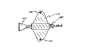
the intravenous catheter example illustrated in Figure 1, a
catheter 100 is placed in a patient's arm 150 to a vein therein.
Once the catheter cannula 100 is inserted to the desired length
inside the patient, the anchoring device of the invention is
positioned directly next to the junction ~i.e., the injection
site). The anchoring device of the invention includes a securing
member 110. The securing member 110 has a tubular body portion
-10- 056301.P003
CA 0222~80 1997-12-23
with an opening extending through the tubular body. The opening
of the securing member 110 has a diameter sized to retain the
catheter cannula 100 by frictionally engaging the catheter cannula
100 such that the securing member 110 is not movable about the
catheter cannula 100. This is best illustrated in the perspective
view of Figure 3 which illustrates the securing member 110
frictionally engaged to the catheter cannula 100. The diameter of
the opening of the securing member 110 can also be sized slightly
smaller than the catheter cannula 100 to impart a compressive
force to the cannula 100, in addition to the frictional force.
Once the securing member 110 is properly positioned at a desired
location, the winged portions of the securing member 110 may be
sutured or taped to the patient~s skin.
Figures 1 and 2 illustrate an anchoring device with a
securing member 110 situated at a desired location adjacent the
catheter hub 120. To position the securing member 110, the
anchoring device of the invention includes a dilator member 140.
The dilator member 140 can slidably move about the catheter
cannula 100. In other words, the dilator member 140 has an
opening with a diameter larger than the catheter cannula 100. The
dilator member 140 is adapted to mate with securing member 110
through a portion of the opening in the tubular body portion of
securing member 110.
Figure 4 illustrates a perspective view of the anchoring
device of the invention about a catheter cannula 100. Figure 4
shows a securing member 110 with an opening that has been dilated
bv dilator member 140 so that securing member 110 does not
-11- 056301.Po03
CA 0222~80 1997-12-23
frictionally engage the catheter cannula 100. Instead, the entire
anchoring device assembly, including the dilator member portion
190 and the securing member portion 110, collectively define an
opening of sufficient diameter to move the anchoring device about
the catheter cannula 100. The dilator member 140 has a score or
slice 145 running along its length to allow the dilator member 140
to be divided into two pieces to facilitate its removal from the
catheter once the securing member 110 is in place.
Figure 5 illustrates a top, cross-sectional view of the
anchoring device of the invention through lines A-A of Figure 4.
Figure 5 shows a dilator member portion 140 that includes a
tubular body portion having an opening extending through the body
portion and a diameter of the opening greater than the outside
diameter of the catheter cannula 100.
Figure 6 illustrates a perspective side view of the
dilator member 140 of the invention. The dilator member 140
includes a substantially tubular body portion with an opening
extending the length of the body portion. The body portion is
made of a durable material like plastics such as polyurethane,
polyethylene, TEFLON~ (produced by E.I. DuPont de Nemours and
Company, Wilmington, Delaware), polypropylene, and polyvinyl
chloride. The body portion of the embodiment shown in Figure 6,
includes a tapered portion 145 to ease insertion and mating with
securing member 110. The dilator member 140 further includes a
section of reduced wall thickness or scored (e.g., sliced with a
blade) section 147 on opposing sides of the dilator member 140.
The reduced thickness portions allow the dilator member to be
-12- 056301.P00:3
- CA 0222~80 l997-l2-23
divided into two pieces to remove the dilator member 140 from the
catheter once the securing member 110 is in place.
Figure 7 illustrates a cross-sectional view of the
adjustable anchoring device of the invention taken through line B-
B of Figure S. In Figure 7, the anchoring device includes asecuring member 110 with an opening dilated by dilator member 140
to expand the opening of the anchoring device such that the
anchoring device can freely move about the catheter cannula 100
and be adjusted at any desired location.
Once the anchoring device, including the dilator member
140 and the securing member 110 is placed in the desired location
about the catheter and in relation to the patient s body, the
dilator member portion 140 is removed and the tubular body portion
of the securing member 110 assumes a diameter that frictionally
lS engages the catheter cannula 100. The opening in the tubular body
portion of the securing member 110 is sized to frictionally engage
the catheter cannula 100 so that the securing member 110 is not
movable about the cannula 100. Thus, catheter cannulas of various
sizes will have anchoring devices, including securing members with
body portions of various diameters to securely engage the
catheters by frictional gripping force. The invention also
contemplates that the opening in the tubular body portion may be
sized slightly smaller than the outside diameter of the catheter
cannula 100. In this manner, the securing member 110
compressively as well as frictionally engages the cannula 100.
An important property of the securing member 110 is that
it is dilatable and will return to its memorized, properly sized
-13- 056301 . P003
CA 0222~80 1997-12-23
diameter once the dilator member 140 is removed. Suitable
elastomeric materials for constructing the tubular body portion of
the securing member so that it is dilatable but will return, in
its non-dilated state, to frictionally or frictionally and
compressively .engage the catheter include, but are not limited to,
silicone, polyurethane, latex, polyvinyl chloride, KRATON~
~produced by Shell Oil Company, ~ouston, Texas), isoprene,
SANTOPRENE~ (produced by Monsanto Company, St. Louis, Missouri),
and HYTREL~ (produced by E. I . DuPont de Nemours, Wilmington,
Delaware).
Figures 8 and 9 illustrate the removal of the dilator
member 140 from the securing member 110 once the securing member
110 is placed in the desired location on the catheter 100. Figure
8 demonstrates that the securing member 110 is held firmly in
place by hand or other means, including sutures, tape, etc., and
the dilator member 140 is advanced away from the securing member
110. Once the dilator member 140 is away from the securing member
110, the securing member 110 frictionally or frictionally and
compressively engages the cannula 100. Also, while pulling the
dilator member 140 away from the securing member 110, the dilator
member is divided and peeled away from the catheter. As noted
~bove, ways that the dilator member 140 may be easily divided
include scoring or slicing opposing side walls or constructing the
dilator member 140 portion with opposing sides of reduced wall
thickness, the division occurring along the portions 147 with
reduced wall thickness, and then pulling the walls apart by hand.
-14- 056301.P003
CA 0222~80 1997-12-23
Figures 8 and 9 describe an embodiment wherein the
dilator member 140 is removed from the catheter once the securing
member 110 is properly placed- The invention contemplates also
that the dilator member may remain on the catheter and used for
catheter reinforcement or kink resistance or the like.
Figures 10 and 11 illustrate different embodiments for
the securing member portion of the anchoring device of the
invention. Figure 10 illustrates a securing member 200 that
includes a tubular body portion 210 that is curved. The curvature
of the tubular body portion 210 of the securing member 200
provides additional gripping support to securely hold the catheter
cannula and can also guide the catheter into a direction different
than the direction the catheter enters the securing member 110.
The invention contemplates that a dilator member is similarly
shaped so as to dilate, if necessary, the entire curved body
portion 210 of the securing member 200. Similarly, Figure 11
illustrates an embodiment of the anchorins device with a securing
member 250 including a tubular body portion 26G that is completely
curved. This allows an IV catheter, for example, to go into a
patient at an angle 180- relative to the direction of the incoming
IV drip line. Again, the invention contemplates that, if
necessary, a dilator member portion will di'ate the entire curved
body portion 260 of the securing member 250.
Figure 12 illustrates another embodime.,t of the securing
member portion of the invention. Figure 12 presents a securing
member 300 with a pair of dilatible annularly shaped portions or
rings 310 that surround the catheter cannula 100. In this
-15- 056301.Po03
CA 0222~80 1997-12-23
embodiment, to dilate the securing member 300, a dilator member
portion must dilate each securing wing 310.
Figures 13 and 14 illustrate other embodiments of the
securing member of the invention. Figures 13 and 14 present
securing member portions wherein the securing device is a non-
tubular section or sections. The securing member 320 of Figure 13
includes an arcuately-shaped or arched body 330 that engages a
catheter cannula. The opening in the arch portion 330
frictionally or frictionally and compressively engages the
cannula. Figure 14 illustrates a securing member 340 that
includes a plurality, in this case, three, arcuately-shaped
portions 350 that are each dilatible and that frictionally or
frictionally and compressively engage the catheter cannula.
Figure 15 illustrates a second embodiment of the dilator
member portion of the anchoring device of the invention. In
Figure 15, the dilator member 360 has a split collar 370 to
facilitate the division of the dilator member 360. In Figure 15,
opposing wings of the collar portion 370 are pulled apart while
the dilator member 360 is separated from the securing member.
The invention further contemplates that the securing
member and optionally the dilator member are pre-loaded on the
catheter body. The pre-loaded embodiment is particularly useful
wherein the opening or openings in the securing member portion are
sized slightly smaller than the catheter cannula. The pre-loaded
embodiment also eliminates the possible misplacement of the
components of the anchoring device and facilitates the simple
installation of the anchoring device. Of course, the invention
-16- 056301.Po03
CA 0222~80 l997-l2-23
also contemplates an anchoring device that is not pre-loaded, but
that is installed on the catheter once the catheter is placed in a
patient. Further, because the dilator member is removed once the
securing member is in place, the anchoring device of the invention
is not bulky or cumbersome.
As noted above, the anchoring device of the invention
may be used to secure any catheter. Figures 16-20 illustrate the
anchoring device for use with an over-the-needle catheter. An
over-the-needle catheter consists generally of a needle coupled to
an extended stylet and a catheter cannula extending over the
needle and the length of the stylet. In an over-the-needle
catheter, the needle and catheter cannula are placed
simultaneously, allowing the use of a smaller needle size, e.s.,
3-4 gauges smaller, than a through-the-introducer type catheter
where the catheter must enter through the opening created by the
needle. In the over-the-needle catheter design, the outside
diameter of the catheter is greater than the opening made by the
needle, .hus allowing a similar diameter catheter to be inserted
with a smaller needle.
A problem associated with over-the-needle catheters is
that it ~an be difficult to insert both the needle and the
catheter cannula at the same time. Since the catheter moves
freely over the needle and stylet, when the needle is inserted,
the catheter may buckle or resist entry. One way to overcome this
problem is through the use of deformable clamping wings which
clamp or pinch the catheter and needle when the wings are folded
together.
-17- 056301 . P003
CA 0222~80 1997-12-23
Figures 16 and 17 illustrate an embodiment of the
invention wherein the securing member 410 includes deformable
wings that, when compressed or folded, clamp or pinch the catheter
and needle or stylet. Figure 16 illustrates the securing member
410 with the wings in a down or unfolded position. Figure 17
illustrates the securing member 410 with wings in a folded or
clamping position on the catheter cannula 400 and the needle 440
coupled to the stylet 450. The anchoring device of this
embodiment works similarly to that described above with reference
to Figures 1-15 including a securing member portion 410 and a
dilator member 420 to dilate the body portion of the securing
member 410. This embodiment adds the additional feature that the
wings are deformable such that the securing member 410 may also
clamp, by applying additional compressive force, the ~atheter
cannula/needle as the cannula and needle are placed in a patient.
Window 430 illustrates that the cannula and needle are squeezed by
the securing device when the wings 410 are folded to impart
additional compressive force. In an unfolded state, a non-dilated
securing member 410 fixedly engages the cannula 400 as described
above.
Figures 18-20 illustrate a further embodiment of the
invention, particularly useful with over-the-ne~dle catheters.
Dilator member 520 is forced into securing member S10 and dilates
the tubular body portion of securing member 510 as described above
with reference to Figures 4-8 and the accompanying text. Dilator
member further extends beyond the securing member 510 and into the
skin/body of the patient as shown in Figure 19. In this manner,
-18- 056301.Po03
- CA 0222~80 1997-12-23
the dilator member 520 acts as an introducer allowing a smoother
transition for placing the catheter cannula, e.g., the over-the-
needle catheter, by freeing the passageway and eliminating any
skin drag. Figure 20 illustrates that once the catheter is
S properly placed, the dilator member 520 may be removed from the
skin/body and the securing member 510 and, optionally, removed
from the catheter completely by division.
In the preceding detailed description, the invention is
described with reference to specific exemplary embodiments
thereof. It will, however, be evident that various modifications
and changes may be made thereto without departing from the ~roader
spirit and scope of the invention as set forth in the claims. The
specification and drawings are, accordingly, to be regarded in an
illustrative rather than a restrictive sense.
-19- 056301.Po03