Note: Descriptions are shown in the official language in which they were submitted.
CA 02225989 1997-12-30
D 96-1-232 PATENT
VEHICLE HEADLAMP SYSTEM
1. The invention relates to electric lamps, and in
particular to headlamps with inserted lamp capsules. More
in particular, the invention relates to the coupling
structure between a headlamp reflector and a light source
lamp capsule.
2. Background Art
Vehicle headlamps are presently made in roughly two
pieces. There is a reflector section which includes the
essential optical reflector, and other housing features such
as a lens cover, mounting and aiming hardware. The second
element is the replaceable light source, or capsule that
latches in place in the reflector. The pattern of light
that appears on the road is the result of both elements, and
great effort has been made in improving both elements.
Further demands for smaller, more compact headlamps,
requires even more control in the manufacture of the
reflector and the lamp capsule. In a 10 centimeter high
headlamp, the misplacement of the light source with respect
to the reflector by as little as quarter of a millimeter can
have a bothersome effect on the beam pattern at 100 meters
distance. Such misdirection of the beam pattern is one
cause of the unpleasant glare drivers experience with
oncoming vehicles. There is then a need to improve the
accurate location of the light source with respect to the
reflector in vehicle headlamps.
Previously, the reflector passage, where the lamp
capsule is inserted has been defined along with its various
coupling features by the exterior side mold wall. It is
common in plastic molding to experience variations in the
process, resulting in variations in the final product. Such
variations as wall thickness, and surface location can occur
due to wear in the mold parts, misplacement between the mold
- 1 -
CA 02225989 2006-06-14
parts, variations in the mold material, flashing and other
molding defects. The result here is an irregular variation in
the dimensions between the inside optical surface, and the
exterior surface. This variation leads to irregular axial (Z
direction) location of the light source. There is then a need
for a headlamp system that prevents variations in the molding
process from effecting the axial positioning of the lamp.
In the past, the reflector and lamp capsule were
manufactured with a small, but none the less, real tolerance
gap measured radially between reflector passage diameter, and
the lamp capsule diameter. This radial wiggle room allowed the
capsule to be inserted into the back of the reflector. In the
final coupling, an 0-ring seal filled and sealed this gap or
wiggle room. The 0-ring then acted to finally position the lamp
capsule. None the less, due to manufacturing variations,
flashing on the seal, flashing on the seal surfaces, too little
grease, inaccurate seal pinching, and over or under pressing of
the seal, the capsule could be twisted or displaced radially
(X, Y directions) from the proper lamp axis direction. This
type of variation leads to irregular beam pointing. There is
then a need for a headlamp system that prevents variations in
the radial positioning of the lamp capsule.
Summary of Invention
An improved vehicle headlamp system is disclosed with an
optical reflector and may have an optical surface side, and a
wall defining a passage formed therethrough. The wall in the
passage area may include an axial locating surface, a planar
locating surface, each locating surface being co-formed with
the optical surface so as to be dimensionally invariant in
manufacture with respect to the optical surface. A lamp capsule
-2-
CA 02225989 2006-06-14
may be coupled into the reflector may be formed having an axial
locating surface, a planar locating surface. The axial and
planar locating surfaces of the optical reflector may be
positioned to be adjacent the respective locating surfaces of
the lamp capsule.
According to one aspect of the invention, there is
provided a vehicle headlamp system comprising: a) an optical
reflector having an optical surface; an optical axis defining
an optical direction; a wall defining a passage formed through
the reflector, the wall including a locating surface, the
locating surface being co-formed with the optical surface so as
to be dimensionally invariant in manufacture with respect to
the optical surface, and b) a lamp capsule supporting a light
source, the capsule having a positioning surface, the locating
surface of the optical reflector being abutted adjacent the
positioning surface of the lamp capsule to thereby accurately
locate the lamp capsule relative to the optical surface.
According to another aspect of the invention, there is
provided a vehicle headlamp system comprising: a) an optical
reflector having an optical surface; an optical axis defining
an axial direction, and at least one perpendicular planar
direction; a wall defining a passage formed through the
reflector, the wall including an axial locating surface, and a
planar locating surface, each locating surface being co-formed
with the optical surface so as to be dimensionally invariant in
manufacture with respect to the optical surface, and b) a lamp
capsule supporting a light source, the capsule having an axial
positioning surface, and a planar positioning surface, the
locating surfaces of the optical reflector being abutted
adjacent the respective positioning surfaces of the lamp
capsule to thereby accurately locate the lamp capsule relative
to the optical surface in the axial and planar directions.
-3-
CA 02225989 2006-06-14
According to another aspect of the invention, there is
provided a vehicle headlamp system comprising: a) an optical
reflector having an optical surface, and a wall defining a
passage formed therethrough, the wall including an axial
locating surface, and a planar locating surface, each locating
surface being co-formed with the optical surface so as to be
dimensionally invariant with respect to the optical surface,
the reflector having a reflector sealing surface around the
formed passage; b) a lamp capsule including a holder having an
axial positioning surface, and a planar positioning surface,
the locating surfaces of the optical reflector being adjacent
the respective positioning surfaces of the lamp capsule; and
including a spring bias providing a force between the refector
and the lamp capsule to press the planar locating surface into
abutment with the planar positioning surface, the capsule
having a capsule sealing surface around the capsule and c) a
gasket formed of a resilient material, positioned between the
reflector sealing surface, and the capsule sealing surface,
forming a seal between the reflector and the capsule holder and
providing a force to press the axial locating surface against
the axial positioning surface into abutment, d) the holder
further retaining a light source having leads extending
therefrom, the leads passing through the interior wall of the
holder, and e) connectors supported in the holder and coupled
to the leads to provide electrical connection to the light
source.
Brief Description of the Drawings
FIG. 1 shows a cross sectional view of a preferred embodiment
of a vehicle headlamp system partially broken away.
-3a-
CA 02225989 2006-06-14
FIG. 2 shows a perspective view of an optical reflector,
partially broken away.
FIG. 3 shows a perspective view of the optical reflector,
partially broken away.
FIG. 4 shows a first perspective view of a lamp capsule.
FIG. 5 shows a second perspective view of a lamp capsule.
FIG. 6 shows perspective view of a spring bias.
FIG. 7 shows cross sectional view a gasket.
FIG. 8 shows a perspective view of a support plate.
FIG. 9 shows a perspective view of a support plate and support
ring.
FIG. 10 shows a perspective view of a holding cup.
FIG. 11 shows a top view of a lamp capsule.
Best Mode for Carrying Out the Invention
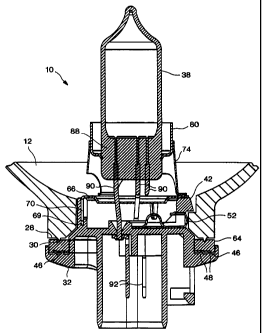
FIG. 1 shows a cross sectional view of a preferred
embodiment of a vehicle headlamp system partially broken away.
Like reference numbers designate like or corresponding parts
throughout the drawings and specification. The vehicle headlamp
system 10 is assembled from an optical reflector 12, a lamp
capsule 32, and a gasket 64. Additional mounting, aiming,
sealing, venting, and similar headlamp features may be selected
or used according to designer choice as known in the art.
-3b-
CA 02225989 1997-12-30
D 96-1-232 PATENT
FIG. 2 shows a perspective view of an optical reflector
12, partially broken away. The optical reflector 12 may be
made out of molded plastic, such as a filled bulk molding
material or other molding material as known in the art. The
reflector has the general form of a concave shell with an
exterior, (or rear) side 14 and an interior, or forward
reflective side, referred to here as the optical surface 16.
The optical surface 16 is designed to provide a desired
headlamp beam pattern as known in the art. The optical
surface 16 may be formed as a female side on a highly
accurate mold wall (male side) referred to here as the mold
wall for the optical surface 16. The opposing mold face,
the one forming the exterior side 14, will be referred to as
the mold wall for the exterior side. The reflector 12 is
initially formed by molding the plastic fill material
between the optical side wall and the exterior side wall of
a mold. In the molding process, the optical surface 16 is
then accurately replicated in the molded plastic by the
intimate contact between the mold wall for the optical
surface 16 and the plastic fill material. The optical
surface 16 may thereafter be coated, if necessary, with
various reflective and protective layers. These additional
layers are not shown.
Extending in a forward direction from the optical
surface 16, is an optical axis 18, generally indicating the
direction of the final headlamp beam. It is understood that
the reflector 12 may be enclosed on the front side by a
clear cover lens that may or may not include beam directing
lens elements. The reflector may be supported by aiming
hardware, and enclosed in a housing as is generally known in
the art. The cover lens, aiming hardware, and housing
designs are matters of designer choice, and are not
important with respect to the present invention.
The optical reflector 12 also has an internal wall 20
defining a passage extending axially between the exterior
- 4 -
CA 02225989 1997-12-30
D 96-1-232 PATENT
surface 14, and the optical surface 16. Formed on the
internal wall 20 are one or more axial positioning surfaces
22, and one or more planar positioning surface 24. The
axial positioning surface 22 and the planar positioning
surface 24 may be formed as extensions of the optical
surface 16 by making the two simultaneously as part of the
same mold wall for t-he optical surface 16. The axial
positioning surface 22 then provides an accurate locating
surface that the lamp capsule 32 can be directly positioned
against for proper location of the lamp capsule 32 in the
axial direction 18 (the Z direction). The axial positioning
surface 22 may be formed as a depression or concavity in an
in-leading ramp 26 facing in the forward axial direction 18
to thereby locate the lamp capsule 32 exactly with reference
to the optical surface 16. Since the axial positioning
surface 22 and ramp 26 are actually continuations of the
optical surface 16, there can be no manufacturing
dimensional variation between the optical surface 16 and the
positioning surface 22.
In the preferred embodiment, the axial positioning
surface 22 and the lead in ramp 26 are repeated as a pattern
in two other locations (not shown) around the internal wall
20. The in-leading ramps 26, may terminate respectively in
notched depressions serving as locating surfaces 22 that can
then capture follower arms 42 extending radially from the
lamp capsule 32. The three preferred axial positioning
surfaces 22 are located approximately equally angularly
around the internal wall 20.
Also positioned along internal wall 20 is the planar
positioning surface 24 for locating the capsule relative to
the X and Y plane. The planar positioning surface 24 may
also be formed as an extension of the optical surface 16 by
making the two with the same mold wall for the optical
surface 16. The planar positioning surface 24 provides a
locating surface that the lamp capsule 32 uses for proper
- 5 -
CA 02225989 1997-12-30
D 96-1-232 PATENT
positioning in directions orthogonal to the optical axis 18
(X and Y directions). The planar locating surface 26 may be
formed as a flat or curved face on the internal wall 20 of
the reflector passage, the normal of which is orthogonal to
the optical axis 18. The preferred planar positioning
surface 24 comprises a circular cylindrical wall section
positioned as a section the internal wall 20 of the
reflector passage. The curved section can then give both X
and Y directions.
FIG. 3. shows an exterior end (back side) view of the
reflector partially broken away, the internal wall 20, and a
reflector sealing surface 28. Positioned along optical
reflector 12 is a reflector sealing surface 28. The
reflector sealing surface 28 allows the reflector passage to
be sealed from the flow of gas, vapor or water to thereby
prevent the reflector cavity, and light source from having
condensed water, dirt or other material interfere with the
lamp operation. The preferred reflector sealing surface 28
is a flat ring, whose normal is approximately parallel to
the optical axis 18. The flat ring, which may be circular
or otherwise, extends on the reflector 12's exterior side 14
around the reflector passage. The preferred sealing surface
28 includes one or more projecting ribs 30 to enhance
sealing.
FIG. 4 shows a first perspective view of a lamp capsule
32. FIG. 5 shows a second perspective view of the lamp
capsule 32. The lamp capsule 32 may be made with a plastic
base 34 of plastic resin, or filled plastic resin. Coupled
to the plastic base 34 may be a metal holder 36, and held in
the metal holder 36 may be a light source 38. The optical
reflector 12 is designed to couple and seal with the lamp
capsule 32. The lamp capsule 32 has an axial locating
surface 40, a planar locating surface 44, a capsule sealing
surface 46, and a spring bias 52. There are numerous base,
- 6 -
CA 02225989 1997-12-30
D 96-1-232 PATENT
and metal holder designs, allowing for accurate positioning
of the light source with respect to the lamp capsule.
The preferred base 34 is roughly a plastic tube adapted
with coupling, locating and sealing features that then
supports a metal holder 36 that clamps to a light source 38.
The preferred light source 38 is a tungsten halogen lamp
bulb. It is understood that the light source 38 may be an
arc discharge source. With respect to the axial and planar
location features described above in the coupling of the
capsule to the reflector, the light source and_ holding
method are matters of design choice. The preferred
inventive design is disclosed below. Other light source
designs and holding methods may be used with the reflector
coupling design.
In the preferred embodiment, positioned along lamp
capsule 32 is at least one axial locating surface 40. The
axial positioning surface 22 of the reflector is designed to
mate face to face with the axial locating surface 40 of the
lamp capsule 32. When the two surfaces 22 and 40 are
properly seated one to the other, the lamp capsule 32 is
then properly positioned with respect to the optical surface
16 along the optical axis 18 (Z direction) . The preferred
lamp capsule 32 axial positioning surfaces 40 are the lower
(exterior side) facing surfaces of three short, arms 42,
extending orthogonal to the lamp axis from the lamp capsule
32. When the lamp capsule 32 is inserted in the reflector
12, each arm 42, passes inward sufficiently to slide up on a
corresponding in-lead ramp 26, formed on the reflector 12.
By rotating the lamp capsule 32, the arms 42 are forced up
the ramps 26, thereby advancing the lamp capsule 32 along
the optical axis (Z direction) while compressing the gasket
64. Once the arms 42, reach the inner ends of the in-lead
ramps 26, the axial locating surfaces 40 abut the
positioning surfaces 22, which may be formed with retaining
- 7 -
CA 02225989 1997-12-30
D 96-1-232 PATENT
depressions or slots, and are held in place by the resilient
compression of gasket 64.
Also, positioned along lamp capsule 32 is a planar
locating surface 44. The planar positioning surface 24 of
the reflector 12 is designed to mate face to face with the
planar locating surface 44 of the lamp capsule 32. When the
planar positioning surface 24, and the planar locating
surface 44 are properly seated one to the other, the lamp
capsule 32 is then properly positioned in the X and Y
directions with respect to the optical axis_ 18 (Z
direction). The preferred capsule planar locating surface
44 comprises a cylindrical face formed on side of the base
34 extending parallel to the optical axis 18. The preferred
planar positioning surface 24 of the reflector and the
planar locating surface 44 of the plastic base 34 are formed
to be conformal with each other when the lamp capsule 32 is
properly positioned in the reflector 12.
Positioned along lamp capsule 32 is a sealing surface
46. The capsule sealing surface 46 allows the lamp capsule
32 to be sealed to the gasket 64, and thereby close off the
reflector passage. The preferred capsule sealing surface 46
is a flat ring, whose normal is approximately parallel to
the optical axis 18. The ring, which may be circular or
otherwise, extends around the lamp capsule 32 so as to
follow along and to mate with the gasket 64 which is also
mated to the corresponding reflector sealing surface 28.
The sealing surface 46 may also include one or more
projecting ribs 48 extending along the length of the sealing
surface 46 to help stabilize the gasket 64 position and
enhance sealing.
The headlamp system 10 may additionally include a
spring bias 52. The spring bias 52 is positioned to act
between the internal wall 20 and the lamp capsule 32 so as
to press between the reflector and the lamp capsule 32 in a
direction orthogonal to the lamp axis 18. FIG. 6 shows
- 8 -
CA 02225989 1997-12-30
D 96-1-232 PATENT
perspective view of a spring bias. In the preferred
embodiment, the spring bias 52 comprises a resilient metal
piece with an inner foot 54 and an outer foot 56 joined by a
resilient spring section 58 of curved metal. Rising from an
outer end of the outer feet 54, 56 is a contact face 60.
The preferred spring bias 52 is located in a cavity 62
formed in the lamp capsule. The feet act as guides to
retain and direct the action of the spring bias. When the
inner foot 54 is properly positioned, the outer foot 56 can
be moved (slide in the cavity) by the spring force and
thereby apply pressure through the contact face 60 that can
slide and press on the internal wall 20. A slide and
helical spring could be used, as a less preferred
alternative. An additional alternative is a flexible curved
band spring, having couplings at one or both ends coupled to
the exterior wall of the lamp capsule 32. For example, the
plastic base 34 may include one or two axially extending
slots along the exterior. The spring bias may be formed
with tips that fit and bind the lamp capsule 32 to the
spring bias. In this form, the spring bias is an arced band
located in the formed passage, between the reflector and the
holder having an uncompressed form that is not conformal
with either the adjacent reflector wall or the adjacent
holder wall. In any case, with rotation, the spring bias 52
is compressed by advancing against the interior wall 20, or
the side of ramp 26 on the adjacent reflector interior wall,
thereby exerting in a direction perpendicular to the axis
18, a locating force from the reflector 12 to the lamp
capsule 32 hereby driving the planar locating and
positioning surfaces into abutment. A similar second spring
bias may be used with reference to a second set of planar
positioning surface. Locating the spring bias on the
reflector is a less preferred variation, since it would be
less expensive to replace the lamp capsule than to replace
the reflector.
- 9 -
CA 02225989 1997-12-30
D 96-1-232 PATENT
FIG. 7 shows a cross sectional view a gasket 64. The
gasket 64 may be made out of any convenient, resilient
compressible sealing material such as resilient plastic, or
rubber material to have the general form of a flat ring that
is roughly circumferentially conformal with the reflector
sealing surface 28 and the capsule sealing surface 46. The
gasket may include ribs, indentations or other formed
features to guide its position or enhance sealing. The
optical reflector 12 then seals to the gasket 64 on one
side, and the lamp capsule 32 seals to the gasket 64 on the
opposite side. The preferred gasket 64 is a flat ring of
silicon rubber. In the present configuration, the gasket 64
does not determine the X, Y or Z location of the lamp
capsule 32, but only seals the through passage and provides
a tension to hold the lamp capsule 32 against the proper Z
locating surface.
Fig. 8 shows a perspective view of a clip ring 66. The
preferred clip ring 66 is designed to clip couple to the
base 34. The preferred clip ring 66 has the general form of
a flat ring 68 with perpendicular, resilient mounting
tongues to snap fit (clip) to retaining notches 69 formed in
the plastic base 34. In one embodiment four pairs (one is
not shown) of metal tongues 70 with latching notches extend
from the ring 68. The tongues 70 may be formed to latch in
slots formed in the plastic base 34 with the ring 68
generally positioned adjacent an upper end of the plastic
base 34. Formed on the ring 68 are contact points 72, such
as three weld points, preferably in a plane perpendicular to
the lamp axis, for mounting to.
Fig. 9 shows a perspective view of a clip ring 66
coupled to the pedestal 74. The clip ring 66 may be welded
at the contact points 72 to a pedestal 74. The preferred
pedestal 74 has the general form of a hollow cylinder with
formed extensions to couple to the contact points 72 of the
clip ring 66. In the preferred embodiment, the pedestal 74
- 10 -
CA 02225989 1997-12-30
D 96-1-232 PATENT
has three legs with turned out feet 76 for welding to the
three weld points (contact points 72) of the clip ring 66.
Shifting the feet 76 on the contact points 72 prior to
welding provides movement of the pedestal 74 with reference
to the clip ring 66. This allows two axes of adjustment
location for the light source. Formed on the upper end face
of the pedestal 74 is a mounting surface 78 to make a
rotational contact surface. The mounting surface 78 may be
a section of a spherical surface, or preferably a circular
cylinder for adjustable, rotational contact thereto,.
Fig. 10 shows a perspective view of a holding cup 80.
The holding cup 80 has the general form of a cup with a
sidewall 82 and a bottom 84. Formed in the bottom 84 is a
hole with latching features designed to couple to the press
seal 88 end of a light source 38. Numerous latching feature
designs are known in the art. The preferred embodiment uses
bent spring tabs 86 that latch in indentations formed in the
press seal 88 portion of the light source 38. The holding
cup 80 includes a mounting surface to be positioned along
the mounting surface 78 of the pedestal 74, and to be
coupled thereto once proper position of the light source 38
is achieved. The sidewall 82 may serve as the locating
surface for mating with the mounting surface 78. A slight
gap between the mounting surface 78 and the sidewall 82
allows the cup 80 to be slid back and forth, rotated and
pitched side to side to provide three more axes of
adjustment location for the light source 38, giving five
axes of adjustment total.
The preferred sidewall 82 extends up from the press
seal 88 region of the light source to extend axially
parallel to, although somewhat radially offset from the
light source 38, at least cover (encircle) the region of the
press seal 88, and preferably somewhat beyond. The pedestal
74 may additionally provide some of this coverage. It
should be understood that the press seal 88 in this context
- 11 -
CA 02225989 1997-12-30
D 96-1-232 PATENT
is meant to include of the envelope region from where it
starts to be deformed, through the actual seal region where
light from the light source may reasonably be expected to be
reflected or refracted. This curved or deformed material
region is commonly irregularly formed during the pressing
process, and light from the light source contacting it can
be reflected or refracted by it in irregular directions,
resulting in uncontrolled light that may become unwanted
glare. Other light may also pass back onto the holder and
support structures, resulting in irregular light projection
in the beam. The cup 80 limits or stops the development of
such stray light. The sidewall 82 of the support cup 80
then acts as a light block for light exiting from or
reflecting from the press seal 88 region of the light source
38. Such cup 80 shielded light is otherwise optically
uncontrolled, and for the most part would result in glare.
In figures 4 and 5, view of the press seal 88 region of the
light source is blocked by the holding cup 80. The inside
of the support cup 80 may be blackened to reduce reflection.
A substantial portion of such light can then be block by
extending the cup sidewall 82 far enough along the envelope
wall. It is understood that a small portion of light may
pass from the press seal 88 back generally towards the light
source, and such light would not be blocked. The offset
openness the ring clip 66, the pedestal 74, and the cup 80
while blocking light, nonetheless provides substantial air
flow around the press seal 88. Fig. 11 shows a top view of
a lamp capsule. The capsule further includes lead passages,
contact lugs 92, and similar elements as known in the art.
To assemble the lamp capsule, the press seal 88 of the
envelope is threaded through the hole in the holding cup 80
to latch the spring tabs 86 to the press seal 88. The cup
80 is positioned adjacent the mounting surface of the
pedestal 74, and the pedestal 74 is positioned against the
ring clip 66. The light source 38 is then adjusted by
- 12 -
CA 02225989 1997-12-30
D 96-1-232 PATENT
moving the cup 80 and the pedestal 74 until the light source
38 is properly located. The cup 80 is then welded to the
pedestal 74. The pedestal 74 is then welded to the clip
ring 66. This forms completed holder subassembly. The
holder subassembly is then aligned with the plastic base 34.
The subassembly is then advanced so the lamp leads 90 are
threaded through guide holes in the plastic base 34 and
mated to their respective contact lugs 92 in the plastic
base 34. Meanwhile the clip ring tongues 70 are advanced
into the latch recesses, where the tongues 70 latch in
place. The subassembly is now coupled to the base 34,
completing the lamp capsule 32.
To assemble the reflector and lamp capsule 32, the
spring bias ( s) 82 is ( are ) first mounted on the lamp capsule
32. The gasket 64 is then positioned around the lamp
capsule 32 adjacent the capsule sealing surface 28. The
light source 38 end of the lamp capsule 32 is then advanced
into the reflector passage. The spring bias 52 presses
against the internal wall 20. The axial follower arms 42,
of the lamp capsule 32 are aligned to pass over the low ends
of the axial locating ramps 24. After the locating arms 42,
have passed the low ends of the ramps 24, the lamp capsule
32 is rotated so the follower arms 42, follow up the ramps
24. The lamp capsule 32 is then advanced axially by the
ramping action during the capsule rotation. The rotation
advances the lamp capsule 32 in the Z direction while
compressing the gasket 64.
The rotation of the lamp capsule 32, causes the
follower arms 42, to mate with the locating surfaces 22,
finally locating and holding the lamp capsule 32 in the
proper axial position. The proper Z location of the lamp
capsule 32 is then set. The lamp capsule 32 is then locked
in place with the lamp capsule 32 position taken directly
from the same surface forming the optical reflector 12.
- 13 -
CA 02225989 1997-12-30
D 96-1-232 PATENT
There is then no mispositioning of the lamp capsule 32 with
respect to the optical surface 16.
Simultaneously, the spring bias 52 of the lamp capsule
32, engages with the side wall of the internal wall 20 and
presses the lamp capsule 32 orthogonal to the lamp axis 18
direction until the locating surface 26, of the internal
wall 20 engages the corresponding planar locating surface 44
of the lamp capsule 32. With increasing rotation, the
spring bias 52 is forced into greater conformal contact with
the surface of the adjacent internal wall 20.. This
compresses the spring bias 52 forcing the reflector 12 into
face to face, conformal, engagement with the lamp capsule 32
along the respective planar surfaces. The proper X and Y
locations of the lamp capsule 32 are thereby set, so the
lamp capsule 32 is then properly located in the plane
orthogonal to the lamp axis 18. The lamp capsule 32 is then
locked in place with the X and Y planar positions taken
directly from the same surface forming the optical reflector
12. There is then no mispositioning of the lamp capsule 32
in the X and Y plane with respect to the optical surface 16.
While there have been shown and described what are at
present considered to be the preferred embodiments of the
invention, it will be apparent to those skilled in the art
that various changes and modifications can be made herein
without departing from the scope of the invention defined by
the appended claims.
- 14 -