Note: Descriptions are shown in the official language in which they were submitted.
., CA 02226411 1998-01-07
~0 97/Q~489 PCT/US96/11466
"CONTROL AND TERMINATIO~ OF A BATTERY
CHARGING PROCESS"
I() Technical Field
This invention relates to battery chargers and, more
particularly, to a method and an apparatus for controlling the charging
process for a battery and for termin~t~ng the charging process.
s Background of the Invention
There are several methods of charging a battery and several
methods of determining when to tenminate the charging process for a
battery. These methods all suffer from the same problem: they will
overcharge a battery. If a battery is overcharged it will produce oxygen
20 on the positive electrode. This oxygen is then consumed by the negative
electrode and the battery will heat up. The risk of some damage to
batteries due to overcharging is normal procedure for most charging
techniques. Battery manufacturers, to somewhat account for this, design
batteries with extra negative electrode material. However, overcharging
2s irreversibly consumes the negative electrode and, once the extra material
is consumed, then future overcharging will reduce the amount of
negative electrode available for the charge storage so the capacity of the
battery will decline.
A well-documented effect of overcharging, particularly
30 using direct current charging, is that the battery voltage will decrease.
This decrease in the battery voltage is frequently referred to as minus
delta V or negative delta V. One method of determining the state of
charge is to detect the occurrence of minus delta V and to termin~te the
charging process on such occurrence. However, this method will reduce
35 the battery life because the minus delta V occurs when an excess of
oxygen is produced by the positive electrode and consumed by the
negative electrode. As a consequence, this method allows the battery
CA 02226411 1998-01-07
,WO 97/p3489 PCTJIJS96~11466
temperature to rise and also allows pressure to build up inside the
battery.
Another method of determining when to terminate the
charging process has been used when the battery is charged by forcing
s pulses of current though the battery and applying a discharge pulse after
each charging pulse. In this method the charging process is terminated
either in response to the average discharge current during the discharge
pulse or in response to the ratio of energy removed by the discharge
pulse compared to the energy provided to the battery during preceding
~() charging pulse. However, there is not a strong relationship between
discharge voltage value and the state of charge of the battery.
Another method of terminating the charging process
provides for sampling the terminal voltage of the battery between
charging pulses a predetermined time after the beginning of the charge.
Another method provides for measuring the battery voltage
when a charging current is being applied and measuring the battery
voltage during a discharging curren~. The two voltage measurements
are compared and the charging process is terminated when there is a
predetermined difference between these voltages. However, the
20 predetermined difference must be selected dlepending upon the type of
battery being charged and the capacity of the battery being charged.
Furthermore, this method does not prevent the oxygen generating
coincident with overcharging because it does not accurately determine
the state of charge of the battery. The reason is that, if the battery is
~5 being charged at a fast rate of charge then, if there is a long discharge
pulse1 a nickel-cadmium (NiCd) or a nickel-metal-hydride (NiMH)
battery will heat up and the amplitude of charging voltage will change
because of the change in battery temperature. Thus, this method is not
accurate for charging large batteries with a high speed of charge,
30 because a minor error in determining the battery status can result in
damage to the battery. To further complicate matters, the battery
characteristics change during the charging cycle and vary from battery
to battery.
Another method of controlling the charging cycle uses a
3~ "resistance free voltage" reading. The no-load ("resistance free")
te~ninal voltage of the battery is measured after the end of a charging
pulse. This voltage is compared with a reference voltage to determine
CA 02226411 1998-01-07
WO 97/03489 PCT/US96/11466
the charging current. The reference voltage may be dependent upon, for
example the ambient temperature. the internal temperature, the internal
pressure, the charging current, or a change in value in the charging
current. However, the measurement of the resistance free voltage must
oc~ur when all the cells in the battery are in an equilibrium mode. If an
equilibrium condition has not been obtained then the voltage
measurement of open circuit voltage can be different depending upon the
time from the end of the previous charging pulse. The equilibrium time
depends on the charging current and the mass transfer capability of the
battery. Also, the accuracy of the measurement of the resistance free
voltage will depend upon the concentration of the electrolyte in the
battery and the age of the battery. The conccntration of electrolyte will
change, due to the porous structure of the pla~es surface, so measurement
of the open circuit voltage milliseconds after the end of a charging pulse
will not produce accurate results. Thus, the battery can be overheated or
destroyed. Further, there are differences between batteries, differences
between types of batteries, and differences in a single battery which
occur during the charge cycle. Thus, selection of the proper reference
voltage may be difficult or very time-consuming.
Any method which rapidly charges a battery must account
for the constantly changing parameters of the battery, such as internal
resistance, polarization resistance, mass transfer condition and
temperature. A rapid charging system typically uses a tapering current
to avoid an overcharge condition and avoid gas production. U.S. Patent
2s No. 5,307,000 discloses using multiple discharge pulses between each
charging pulse and provides for rapidly ch~rging a battery with high
charging pulse currents for a longer period of time, without marginal
voltages per cell and heat production. Without a plurality of
depolarization pulses the voltage on the battery will rise very fast, due to
a rapidly increasing concentration of electrolyte around the electrodes,
particularly at the end of a charging pulse.
A rapid charging process must be based on a reliable and
precise method of charging control and charge termin~tion. Some
previous charging methods have relied upon temperature cutoff, or
other methods that are not appropriate and/or uniform for all types of
batteries, and methods that even required selection of the battery
capacity even when used for charging the same battery type (lead-acid,
CA 02226411 1998-01-07 ~ . ~ -
,WO 97/Q3489 PCT/US96~1~466
NiCd, NiMH). Other previous charging methods have relied upon
voltage cutoff. However, a fixed voltage threshold is not reliable because
the proper voltage threshold varies, depending upon the condition of the
battery, the temperature, and the battery ' s previous use and charge
5 history.
As is known in the prior art, the preferred technique for
rapidly charging a battery involves forcing a high charging current into
the battery, preferably by applying a series of charging and depolarizing
pulses to the battery. As the chargimg process becomes faster and the
10 instantaneous charging currents become higher, it is much more difficult
to determine when the battery is ful~y charged and when the optimum
time to terrninate or modify the charging process occurs. Without
precisely knowing when the battery is fully charged, both charging time
and energy are wasted due to overcharging of the battery.
However, as stated above, overcharging causes gassing,
generates heat, and increases pressure within the battery, thereby causing
damage to the battery or potentially initiating a catastrophic thermal
runaway condition in the battery. It is known that the battery is charged
when the charging current has stabilized or has begun to increase after a
20 gradual decrease during a constant voltage charging mode. However,
this method relies upon a change in the terminal characteristics of the
battery which occur when the battery is in close proximity to a therrnal
runaway condition. Thus, it is desirable to determine if the battery is
charged without the battery being close to entering a thermal runaway
2s condition.
It is possible to avoid the problems of gassing, heating,
thermal runaway, and other damage to the battery by reducing the
charging currents, extending the charging time, or termin~ting the rapid
charging process at an early point based upon some selected criteria, for
30 example, the amount of time that the charging process has been applied,
the ampere-hours of charge forced into the battery, or the battery
temperature. However, these methods may prematurely tern~in~te the
charging process, thereby leaving the battery in an undercharged
condition, or substantially extend the time that is required for a
35 subsequent method, such as a trickle charge, to bring the battery to a full
charge. Also, using time or ampere-hours of charge as the determining
criteria will cause catastrophic failure for a fully charged or nearly fully
-
CA 02226411 1998-01-07
WO 97/03489 PCT/US96/11466
charged battery if a rapid charging process is applied to the battery
because the battery will not be able to accept the high charging pulse
currents. In this case, gassing and excessive heating of the battery will
begin to occur almost immediately.
Therefore, there is a need for a method of accurately
deterrnining the state of charge of a battery, especially during a rapid
charging process, so that the rapid charging process can be used as long
as possible, thereby bringing the battery to or very near a fully charged
condition, but the rapid charging process will be terminated at a point
before damage occurs to the battery.
Further, during rapid charging process, at some point as the
battery is becoming substantially charged, the battery may not be able to
accept the full current from a charging pulse. Thus, scme of the charge
current delivered during the charging pulse causes gassing and heating.
However, telminating the rapid charging process at this time would be
premature because the battery is not fully charged and is still amenable
to a rapid charging process, but at a lower charging current. Therefore,
there is a need for a method of modifying a rapid charging process, as
the battery is becoming charged, so as to continue rapidly charging the
battery in an efficient manner.
Therefore, there is a need for a method of modifying a
rapid charging process, as the battery is becoming charged, so as to
continue rapidly charging the battery in an efficient manner.
Summary of the Invention
The present invention is directed to accurately determining
when a battery is charged. This allows a rapid charging process to be
used as long as possible, thereby substantially charging the battery, but
terminates the rapid charging process ' at a point which avoids
overcharging the battery and thus avoids wasted charging time and
energy and damage to the battery.
In the present invention, to determine when a battery is
charged, a charging pulse is applied to the battery and then at least two
discharging (depolarization) pulses are applied to the battery. The
battery voltage is measured at a predetermined point in a rest (wait)
period after a first depolarizing pulse and at the same relative point in a
rest period after a second depolarizing pulse. The depolarizing pulse is
-
CA 02226411 1998-01-07
,WO 97/03489 PCT/US96~11466
created by applying a load across the terminals of the battery and is
typically of a significantly shorter duration than the charging pulse.
VVhen a charging pulse is applied to a lead-acid battery, the
lead sulfate in the battery solution is converted into lead, lead oxide, and
electrolyte ions. The lead and lead oxide are deposited on the respective
electrodes. The electrolyte ions are formed at the electrodes and
surround the electrodes. These electrolyte ions are dispersed by a
transport phenomena due to the difference in the concentrations of the
ions around the electrodes and the concentrations of the ions in the
1 () solution.
When a battery is mostly uncharged, the concentration of
the electrolyte is small. Thus, the electrolyte ions fo~ned around the
electrodes are rapidly dispersed into the solution. However, when the
battery becomes mostly charged, the difference in the concentrations is
ls small and thus the ions disperse more slowly. Until the ions disperse, the
lead sulfate cannot move to the vicinity of the electrodes. Thus, the ions
forrn a barrier around the electrodes and prevent the electrodes from
efficiently accepting another charging pulse. Further, there is less of the
solution which can be converted by the charging process. Once this
occurs, the charging voltage must be increased in order to force the
battery to accept the same amount of charging current. However,
increasing the charging voltage causes the water in the battery to
disassociate into hydrogen gas and oxygen gas. The oxygen gas is
rapidly reabsorbed into the solution. However, the hydrogen gas is
absorbed very slowly and so the battery internal pressure builds up. If
venting occurs the hydrogen gas is lost and so the battery has lost water.
The battery will fail if this occurs too many times. Further, the higher
voltage needed to charge the battery causes undesired heating of the
battery and excessive heating may cause battery failure.
The present invention discloses that the state of charge of
the battery, that is, the concentration of the electrolyte in the solution,
can be determined by measuring the open circuit voltage of the battery
during rest periods following discharge pulses. If the open circuit
voltage is approximately the same from one rest period to a subsequent
rest period, then the battery is not being overcharged so the charging
current need not be changed. If the open circuit voltage decreases from
one rest period to a subsequent rest period, then the battery is bçing
CA 02226411 1998-01-07
~0 97/0~489 PCT/US96111466
overcharged or is being charged at a rate higher than the battery can
accept so the charging current shollld be decreased or the charging
process te~Tnin~ted.
Thus, when the battery becomes charged, the charging
s current should be reduced to the level that the battery will efficiently
accept.
In the present invention, the battery is determined to be
efficiently accepting a charge and the charging current need not be
changed as long as the second voltage measurement is approximately the
0 same as the first voltage measurement.
Also, in the present invention, the battery is determined to
be mostly charged and the charging current should be reduced when the
second voltage measurement ls less than the firs~ ~oltage measurement by
some predetermined voltage difference (~V).
Thus, the present invention provides for accurately
deterrnining the state of charge of the battery in a rapid charging process
and controlling or termin~ting the charging process to avoid damage to
the battery.
Therefore, it is an object of the present invention to provide
20 a method of more precisely determining the stat~ of charge of a battery
by comparing the battery voltage between different rest periods.
The present invention provides a method for charging a
battery. The method includes the steps of applying a charging pulse
which provides an average charging current, applying a first
25 depolarizing pulse, waiting for a first rest period. measuring the voltage
of the battery at a predetermined point within the first rest period,
applying a second depolarizing pulse~ waiting for a second rest period,
measuring the voltage of the battery at the predetermined point within
the second rest period, deterrnining a difference between the voltage at
30 the predetermined point within the ~lrst rest period and the voltage at the
predetermined point within the second rest period, and changing the
average charging current depending upon the amount and polarity of this
difference.
In one aspect of the present inverltion the steps of applying
35 the charging pulse, applying the first and second depolarizing pulses,
waiting for the first and second rest periods, and measuring the voltages
CA 02226411 1998-01-07
WO 97/~3489 PCT/IJS96J11466
within the first and second rest periods are repeated if the difference is
within specified limits.
In another aspect of the present invention the charging pulse
has a charging pulse duration and the step of changing the average
s charging current comprises changing the charging pulse duration.
In another aspect of the present invention the charging pulse
has a charging pulse current amplitude and the step of changing the
average charging current comprises changing the charging pulse current
amplitude.
n In another aspect of the present invention the charging pulse
has a charging pulse repetition rate and the step of changing the average
charging current comprises changing the charging pulse repetition rate.
In another aspect of the present invention each depolarizing
pulse has a depolarizing pulse current amplitude and the method further
includes changing the depolarizing pulse current amplitude when the
average charging current is changed.
In another aspect of the present invention each depolarizing
pulse has a depolarizing pulse duration and the method further includes
changing the depolarizing pulse duration when the average charging
current is changed.
In another aspect of the present invention a number of the
depolarizing pulses follows each the charging pulse and the method
further includes changing the number of the depolarizing pulses when
the average charging current is changed.
The present invention also provides a method for charging a
battery by a pulse charging process. The method includes applying a
charging pulse, applying a first depolarizing pulse, waiting for a first
rest period, measuring the voltage of the battery at a predetermined
point within the first rest period, applying a second depolarizing pulse,
waiting for a second rest period, measuring the voltage of the battery at
the predetermined point within the second rest period, determining a
difference between the voltage at the predetermined point within the first
rest period and the voltage at the predetermined point within the second
rest period, and terminating the pulse charging process if the difference
is greater than a predetermined threshold.
The present invention also provides a method for
determining the condition of a battery. The method includes applying a
. CA 02226411 1998-01-07
WO 971b3489 PCT/US96/11466
chargin~ pulse to the battery, applyin~ a first depolarizing pulse to the
battery, waiting for a first rest period, measuring the voltage of the
battery at a first predetermined point within the first rest period,
measuring the voltage of the battery at a second predetermined point
within the first rest period, applying a second depolarizing pulse to the
battery, waiting for a second rest period, determining a difference
between the voltage at the first predetermined point and the voltage at
the second predetermined point, and indicating that water should be
added to the battery if the difference is greater than a predeterrnined
threshold then.
The present invention also provides a method for
teITninating the charging process for a battery. The method includes
applying a charging pulse to the battery, applying a first depolarizing
pulse to the battery, waiting for a first rest period, measuring the voltage
of the battery at a first predetermined point within the first rest period,
measuring the voltage of the battery at a second predetermined point
within the first rest period, applying a second depolarizing pulse to th
battery, waiting for a second rest period, measuring the voltage of the
battery at a first predetermined point within the second rest period,
measuring the voltage of the battery at a second predetermined point
within the second rest period, determining a first difference between the
voltage at the first predetermined point within the first rest period and
the voltage at the second predetermined point within the first rest period,
determining a second difference between the voltage at the first
predeterrnined point within the second rest period and the voltage at the
second predetermined point within the second rest period, and
termin~ting the charging process if both the first difference is greater
than a predetermined threshold and the second difference is greater than
the predeterrnined threshold.
Other objects, features, and advantages of the present
invention will become apparent upon reading the following description
of the preferred embodiment, when taken in conjunction with the
drawings and the claims.
CA 02226411 1998-01-07
WO 97/0,3489 PCT~S96J1~466
Brief Description of the Drawings
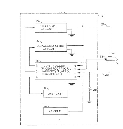
Figure 1 is a block diagram of a battery charging circuit
used in the present invention.
Figures 2A-2B show wavefoIms which illustrate a battery
s charging process and how the state of charge of the battery is determined
by comparing voltage measurements taken in dif~erent rest periods.
Figure 3 is a flow chart illustrating the process of
deterrnining the state of charge of the battery.
Figure 4 shows waveforms which illustrate a battery
1() charging process and how the condition of the battery is determined.
Figure 5 is a modification of the flow chart of Figure 3
which illustrates the process of determining the condition of the battery.
Detailed Description of the Invention
Turning now to the drawing, Figure l is a block diagram of
a battery charging circuit used in the present invention. The battery
charging and discharging circuit 10 comprises a keypad 12, a controller
13, a display 14, a charging circuit 15, a discharging (depolarization)
circuit 16, and a current monitoring circuit 20. The keypad 12 is
20 connected to the "K" input of the controller 13 and allows the user to
input specified parameters such as the battery type (lead acid, NiCd,
NiMH, etc.) and other relevant information, such as nominal battery
voltage or number of cells in series. The keypad 12 may be a keyboard,
dial pad, array of switches, or other device for entering information.
25 To simplify operations by the user, the controller 13 may be
preprogrammed with the parameters for a plurality of battery types. In
this case, the user would simply enter a battery type, such as a model
number, and the controller 13 would automatically use the parameters
appropriate for that battery type. The display 14 is connected to the "S"
30 output of the controller 13 and displays the information, choices,
parameters, etc., for the operator, and provides for audible and visible
alarms or alerts for the operator.
The "C" output of the controller 13 is connected to the
charging circuit I S . The charging circuit 15 provides a charging
35 current to the battery 11. Depending upon the application, the charging
circuit 15 may be configured by the controller 13 to perform as a
constant voltage source or as a constant current source. The "D" output
.
CA 02226411 1998-01-07
WO 97/Q34X9 PCT/US96/11466
Il
of the controller 13 is connected to the discharging (depolarization)
circuit 16, which may be configured by the controller 13 to provide a
constant depolarization current to the battery 11, apply a selected load to
the battery 11, or apply a lower voltage or a reverse voltage to the
s battery 11. The pulse width of the pulses provided by circuits 15 and 16
are controlled by the controller 13. The output of the charging circuit
15 and the dischargin~ circuit 16 are connected to the positive terminal
of the battery 11 via conductor 21. The negative terminal of the battery
11 is connected to circuit ground through a current monitoring resistor
lo 20. Current flowing into or out of the battery l l may therefore be
determined by measuring the voltage across the current monitoring
resistor 20 on conductor 22. The current monitoring resistor 20
therefore functions as a current monitor and current limiter. Of course,
other devices may be used to determine battery current.
lS Battery voltage is monitored by measuring the voltage
between conductor 21 and circuit ground. The effects of the current
monitoring resistor may be elimin~ted by measuring the voltage between
conductors 21 and 22, or by subtracting the voltage on conductor 22
from the voltage on conductor 21. Conductors 21 and 22 are connected
20 to the "V" and "I" input, respectively, of the controller 13.
Battery presence may be determined by activating the
charging circuit lS and monitoring the output of the current monitoring
resistor 20 to determine if charge current is flowing, by activating the
discharging circuit 16 and monitoring the output of the current
2s monitoring resistor 20 to determine if charge current is flowing, by
monitoring the voltage with both circuits 15 and 16 deactivated to
determine if a battery is present, etc.
Temperature sensor 23 monitors the temperature of the
battery 11 so that the controller 13 can adjust the magnitude, number,
30 and duration of the charging pulses and the depolarizing pulses and the
duration of the rest periods in order to m~int~in the desired battery
temperature. Temperature sensor 23 preferably is immersed in the
electrolyte solution of each battery cell to accurately report the internal
battery temperature, even though only one is shown in the drawing.
35 Temperature sensor 23 can be a thermostat, thermistor, thermocouple,
or the like and is connected to the "T" input of the controller 13.
CA 02226411 1998-01-07
Y~O 97/0~3489 PCT/US96/11466
12
The controller 13 comprises a microprocessor, a memory,
at least part of which contains operatin~ instructions for the controller
13, timers. and an analog-to-digital converter. Using a microprocessor-
based controller is advantageous because a microprocessor can make
s very rapid decisions. store voltage and current measurement data, and
perform calculations on data, such as averaging, comparing, and
detecting peaLis. The timers, which can be discrete or implemented by
the microprocessor, may be used for controlling the duration of any
charging pulsest depolarizing pulses, or rest periods as well as provid~ng
lo time references between consecutive depolarizing pulses or rest periods.
The analo~-to-digital converter, which can be discrete or implemented
by the microprocessor, may be used to convert the voltage or current
signals into a form usable by the digital microprocessor. A digital
controller is discussed because it is the preferred embodiment, but an
analog controller may also be used to implement the present invention.
Figures 2A-2B show waveforrns which illustrate a battery
charging process and how the state of charge of the battery is
determined. The state of charge is determined by comparing voltage
measurements taken in different rest periods. The voltage and current
waveforms generally illustrate the charging process which applies one or
more chargin~ pulses C1, preferably followed by a rest period CWl,
and a plurality of depolarizing pulses Dl - D3, each depolarizing pulse
D 1 - D3, preferably followed by a rest period DW I - DW3,
respectively.
2s For convenience of illustration, the charging pulses and
depolarizing pulses are illustrated as rectangular pulses but it should be
appreciated that this is often not the case in actual practice and thus the
present invention should be understood to include, but not be limited to,
rectangular waveforms. Also, for convenience only and not by way of
limit~tion, the charging pulses C1, C1' are shown to have the same pulse
width and the same charge current amplitude IA, and the depolarizing
pulses D1 - D3 are shown to have the same pulse width and the same
discharge current amplitude IB. Additionally, the number of
depolarizing pulses shown is purely for convenience and not by way of
limitation. The rest periods CW1 and DWl - DW3 are shown to be of
the same duration only for convenience and not by way of limitation.
. . ~ CA 02226411 1998-01-07 ,
~0 97/0~3489 PCT/US96/11466
13
The controller 13 may alter the duration of such rest periods based on
monitored changes in the state of charge of the battery.
First, with respect to comparing voltage measurements
taken in different rest periods, specific voltage measurements Vl and V2
are shown on the voltage waveform in Figures 2A - 2B. V1 and V2 are
output voltage measurements of the bat~ery taken when the battery is in
an open circuit configuration during rest periods DW 1 and DW2,
respectively. It should be understood that the first output voltage
measurement Vl can be made in the beginning. middle, or end of the
0 rest period DW1, so long as the subsequent output voltage measurement
V2 is taken at the sarne relative point in the next rest period DW2. The
voltage levels during rest periods DW I - DW3 are measured and
evaluated by the present invention.
In Figure 2A it is seen that the volta~e V1 is approximately
equal to the voltage V2. This approximate equality in voltage indicates
that this battery is being not being overcharged. Therefore, the charging
current IA need not be adjusted.
In Figure 2B it is seen that the voltage Vl is greater than the
voltage V2. If the difference between V1 and V2 in Figure 2B is less
than 10 millivolts per cell then the charging current IA need not be
adjusted. However, if the difference between V1 and V2 in Figure 2B is
greater than 10 millivolts per cell then this decrease in voltage from Vl
to V2 indicates that this battery is being overchar~ed. This may be due
to the battery reaching a full charge or may be due to the battery being
unable to accept the full charging current IA for the duration of Cl for
whatever reason. Therefore, the charging current IA should be
decreased until the difference is less than 10 millivolts per cell.
FIG. 3 is a flowchart for determining if a battery is charged
by comparing voltage measurements taken during one or more rest
periods. In step 301, the initial charging parameters are set by the user,
such as the battery voltage or number of cells in the battery and the
discharge rating (C) for the battery. The controller 13 then determines
the charging current IA and the depolarizing current IB for the battery.
This may be based upon a look-up table or an equation, as preferred.
In step 303 the controller 13 applies a charging pulse Cl of
current amplitude IA to the battery, preferably but not necessarily
followed by a rest period CWl, and then applies a depolarizing pulse Dl
-
CA 022264ll l998-0l-07 ' ~ . ~ -
~WO 97/03489 PCT/US96/11466
14
to the battery of current amplitude IlB to the battery. The controller 13
waits for a predete~nined period of time DWl and measures an output
voltage Vl of the battery at a predetermined point in the rest period
DW1. Controller 13 then applies another depolarizing pulse D2 of
current amplitude IB to the battery. The controller again waits for a
predetermined period of time DW2 and measures another output voltage
V2 of the battery at a corresponding predet~rmined point in the second
rest period DW2. It should be understood that the first output voltage
measurement Vl can be made in the beginning, middle, or end of the
In first rest period DW l, so long as the subsequent output voltage
measurement V2 is taken at the same relative point, relative to the
beginning of the rest period, in the next rest period DW2.
Decision 309 tests whether the difference (Vl-V2) is greater
than some maximum difference voltage (VDMAX). If not, then the
battery is not yet charged and the average charging current does not
have to be adjusted. In this case controller 13 will proceed to step 313.
If VD>VDMAX, then the battery is being overcharged or is
being charged at a rate greater than the battery can properly accept.
Therefore, in step 311 the controller 13 decreases the average charging
current. Controller 13 then proceeds to step 313.
In step 313 the controller 13 determines whether to
termin~te the pulse charging process. The pulse charging cycle may be
telminated for any one of several different reasons. For example, the
charging time set by the user may have expired, or the battery
temperature may be outside of an acceptable range, or the amplitude of
the charging current IA may have been reduced to C/10 or less.
If a reason for termin;t~ion of the pulse charging process has
occurred then in step 315 the controller 13 will terminate the pulse
charging process and will switch to another charging process, for
example, trickle charging if termination is because the charging current
is C/10, or the controller 13 will stop the charging process entirely, for
example, if termination is because time has expired or the temperature is
unacceptable. Also, a visual or audible indication of termination of the
charge process may be provided to the operator.
If, at step 313, controller 13 determines that the pulse
charging process is not to be termin~ted then controller 13 will return to
step 303.
CA 02226411 1998-01-07
WO 97/Q3489 PCT/US96tll466
Figure 4 shows wavefo~ns which illustrate a battery
charging process and how the condition of the battery is determined. In
this procedure, the open circuit battery voltage is measured at the
beginning and at the end of the rest periods. For convenience of
illustration, and not as a limitation, the voltage is shown as essentially
constant during a rest period. However. in practice, the voltage may
vary during a rest period and this provides further info~nation as to the
condition of the battery~ especially for lead-acid and NiCd batteries. If
the voltage drops by more than a predetermined amount during a rest
period (VD1=V5-V6 and VDl>VDlMAX) then the electrolyte
concentration is above normal and water should be added to the battery.
Audible and visual alarrns may be used to alert the operator to this
condition and the charging process may be automatically terminated.
Preferably, the measurements are made during the first rest period
lS DWl.
Also, if the voltage measurements at the beginning and at
the end of one rest period (V5 and V6, respectively) are different by
more than some predetermined amount (VDl=VS V6 and
VDl>VD2MAX), and the voltage measurements at the beginning and at
the end of a subsequent rest period (V7 and V8, respectively, or V9 and
V10, respectively) are also different by more than the predetermined
amount (VD2=V7-V8 and VD2>VD2MAX), then this is an indication
that the battery is not properly accepting the charge and therefore the
charging process should be termin~ted.
Figure S is a flow chart illustrating a variation of the
process of determining the condition of the battery. The process of
Figure 5 is identical to the process of Figure 3 except that step 503
replaces step 303, and decision 513 provides an explanation of some of
the termination steps of decision 313. In step 513, additional voltage
measurements V5, V6, V7, and V8 are taken, and voltage differences
VDl and VD2 are determined.
In decision 513A, the controller 13 determines whether the
voltage difference VDl is greater than a predetermined maximum
difference VDlMAX. If so, then in step 513B the controller 13 initiates
an alarm to signal the operator to add water to the battery and then
preferably termin~tes the charging process. If not, then in decision
513C the controller determines whether VDl is greater than a
- CA 02226411 1998-01-07
WO 97/03489 PCT/US96/11466
l~i
predetermined maximum VD2MAX and VD2 is also greater than
VD2MAX. If both conditions are met then the controller 13 terminates
the charging process. The controller I3 may also signal the operator of
the termination. If not then the controller 13 returns to step 503.
In the present invention, as described above, the charging
current may be adjusted by adjusting IA, by adjusting the duration of the
charging pulse, by adjusting the repetition rate of the charging pulses, by
adjusting the number or the duration of the depolarization pulses, or by
adjusting the duration of one or more of the rest periods CW1, DWl,
l O DW2, etc . Preferably, when the charging current is adjusted, the
depolarizing current is adjusted similarly, such as by adjusting IB, by
adjusting the duration of the depo!arizing pulses, or by adjusting the
number of depolarizing pulses between each charging pulse.
As an example of the above process, for a lead-acid sealed
IS battery with a 0.62 ampere-hour rating (C=0.62), IA is 2.4 amperes for
lS0 milliseconds, IB is S amperes for 2 milliseconds, and DWl and
DW2 are 12 milliseconds, and the repetition rate of the charge pulse
(approximately 2 charge pulses per second) is such that the average
charging current is 0.75 amperes (about 1.2C). CW1 may be used or
may not be present. In this example, the pulse charging process will be
terminated when the average charging current drops to 0.0623 amperes
(O.lC). ~s another example, for a lead-acid sealed battery with a 52
ampere-hour rating (C=52~, IA is 100 amperes and IB is 250 amperes,
and the duration of the charge pulse is such that the average charging
current is 60 amperes (about 1.2C), and the pulse charging process wil
be terminated when the average charging current drops to 5.2 amperes
(O.lC).
Comparing the measured battery output voltage for
consecutive rest periods after depolarizing pulses gives a better
indication of the state of charge than in the prior art. As a result, this
me~hod (1) allows charging the battery as rapidly as possible, (2) avoids
heating of and damage to the battery which may occur with continued
charging or overcharging, and (3) allows earlier termination or
modification of the charging process without overcharging of the
battery.
Although it preferable to use the battery voltages measured
during DWl and DW2, the present inventiom is not so limited. I'he
battery voltages may be measured for any two consecutive or non-
,
CA 02226411 1998-01-07
'
WO 97/Q3489 PCTIUS96/11466
17
consecutive discharge rest periods which are not separated by a charging
pulse. For example, DW2 and DW3 may be used, or DW1 and DW3
may be used.
Further, the depolarization pulses may have the same
5 amplitude or may have different amplitudes. Likewise, the
depolarization pulses may have the same duration or may have different
durations. In addition, the rest periods may have the same duration or
may have different durations.
Although the present invention has been described with
0 particularity with respect to sealed lead-acid batteries, the present
invention is not so limited. The present invention is also useful for other
types of batteries, for example, NiCd, NiMH, nickel-iron, nickel-zinc,
silver-zinc, lithium-metal oxide. Iithium ion-metal oxide, non-sealed
lead-acid, etc.
It will be appreciated from the above that the present
invention provides a method and an apparatus for rapidly charging a
battery in a manner which does not cause overheating of the battery.
It will also be appreciated from the above that the present
invention provides a method and an apparatus for charging a battery at a
20 rate that the battery can accept without damage.
The present invention also provides a method and an
apparatus for determining the condition of a battery, including
determining whether water should be added to the battery.
From a reading of the dlescription above of the preferred
2s embodiment of the present invention, modifications and variations
thereto may occur to those skilled in the art. Therefore, the scope of the
present invention is to be limited only by the claims below.
,