Note: Descriptions are shown in the official language in which they were submitted.
CA 02226467 1998-01-07
WO 97/42651 pcTlls97looso6
Integrated hid reflector lamp
BACKGROUND OF THE INVENTION
The invention relates to an integrated reflector lamp comprising a light
source energizeable for çmitting light, a reflector body having a reflective surface for
directing light emitted by the light source, and a lamp base having lamp contacts electrically
5 connected to the light source.
Such lamps are well known in the industry and include, for example,
parabolic alumini7ed reflector (PAR) lamps. PAR lamps have a sturdy lamp envelope with a
pressed glass reflector body having an internal parabolic reflective surface and a pressed
glass cover hermetically sealed to the reflector body. Historically, the light source has been
10 an inc~ndesc~nt filament. More recently, the light source has been a halogen burner, which
provides greater efficacy than with a conventional bare incandescent filament. Still further
improvements in the art have led to the use of halogen burners which include infrared
refle~tive coatings on the burner capsule or on a sleeve within or outside the burner capsule.
The coating reflects otherwise-was~ed infrared radiation back onto the filament. This raises
15 the t~--,peldture of the fil~ment and increases useful light output for a given power
consumption.
PAR lamps come in many different sizes and have many different
applications. These include general indoor and outdoor spot and flood lighting, such as for
bniltling.s, statues, fountains and sports grounds, as well as accent lighting, such as for retail
20 store window displays, hotels, restaurants and theaters.
As part of a worldwide movement towards more energy efficient
lighting, recent government legisl~tion in the United States (commonly referred to as the
National Energy Policy Act "EPACT") has m~n~tPd lamp efficacy values for many types of
commonly used lamps including parabolic alurnini7ed reflector (PAR) lamps. These25 minimum efficacy values became effective in 19g5 and only products meeting these efficacy
levels are allowed to be sold in the United States. The efficacy values for PAR-38
in~nrlP.sc~nt lamps have been established for various wattage ranges. For example, lamps of
51-66 W must achieve 11 lumens per Watt (LPW), lamps of 67-85 W must achieve 12.5
LPW, lamps of 86-115 W must achieve 14 LPW and lamps in the range 116-155 W must
CONFIRMATION COPY
CA 02226467 1998-01-07
W O 97142651 2 PCT~B97/00506
achieve 14.5 LPW.
There are few PAR 38 lamps currently on the market with a reflective
coating of ~ llll and an in~n~escent filament which pass the EPACT standards andwhich have a corrlrnercially acceptable life of 1000 hours. Those that do barely exceed the
minimtlm standards, and further subst~nti~l improvements seem unlikely. Accordingly, the
market is rapidly shifting to PAR lamps which have halogen burners or halogen IR burners.
However, one disadvantage of commercial halogen and halogen IR lamps
is their relatively short lifetime for acceptable efficacy. For exarnple, a comrnercially
available 90 W lamp has an average lifetime of about 2500 hours while that of a 60 W
halogen IR lamp is only slightly greater at 3000 hours. It would be desira~le to have a
significantly longer lifetime since re-lamping, especially for fixtures in high places, can
easily exceed the cost of the }amp being replaced. Another disadvantage is the luminous
efficacy is limited to below about 20 LPW. For example, the 90 W halogen PAR lamp has a
luminous efficacy of about 16 LPW while the 60 W PAR with a halogen IR burner has a
luminous efficacy of about 19 LPW. Further improvements in efficacy for these lamps at a
fixed life would be expected to be less than about 5 % . Still another disadvantage is Ihat the
color temperature is limited for tungsten filament lamps to a maximum of 3650 K, the
melting point of tungsten. Typically, however, the color temperature is confined to a range
of about 2600-3000 K to achieve a commercially acceptable lamp life. It would be desirable
to offer lamps with a different color temperature because this enables the lamp to be tailored
for specific applications. For example, it is generally desirable that for cool environments a
warm color temperature (for example 3000 K)is desired whereas for a warm environment a
cool color temperature (for example 4500 K) is desired.
Still other reflector lamps are known which include a blown glass
envelope and contain a bare inr~n~eSCent filament. These are generally known as "R" lamps,
and have even lower luminous efficous than the PAR lamps, for example on the order of 9-
11 LPW, and the same colorimetric limitations.
SUMMARY OF THE INVENTION
Accordingly, it is an object of the invention to provide a reflector lamp
with improved efficacy.
It is another object to provide a reflector lamp with improved lamp life.
It is yet another object to provide a reflector lamp with greater flexibility
with respect to photometric parameters such as color te~ eldlure and color rendering.
CA 02226467 1998-01-07
WO 97/42651 3 PcT/Isg7/00506
It is a further object of the invention to provide such a larnp which can
be operated in the same fixtures as incandescent and halogen PAR lamps and incandescent
"R" lamps.
According to the invention, the above ob3ecls are accomplished in that a
5 lamp according to the type described in the opening paragraph as defined in claim 1.
The above-described embodiment provides a reflector lamp which is a
significant energy-saving sukstitn~e for the known PAR lamps having an inr~n~escent
fil~ment, including halogen and halogen IR lamps, as well as the known r'R" lamps. The
lamp according to this embodiment fits in the same fixtures as the correspondin~ lamp,
10 screws into the same sockets, and operates off of the same power line voltage. Thus,
retrofitting is simple. Furtherrnore, in addition to the substantially improved luminous
efficacy, the gas discharge device can be d~si~nP~, through selection of the fill constilueMs
such as with different metal halides, to have colorimelric parameters, such as color
temperature, over a wider range than is possible with the known PAR lamps and the R
15 lamps. Thus, there is greater flexibility for the larnp designer tO tailor the lamp to a
particular environment. According to one commercially significant implementation, the lamp
has an outline substantially within that of the ANSI outline for a PAR 38 lamp, which is
widely used in lighting public space~.
According to yet another embodiment, during normal lamp operation the
20 discharge device is free of acoustic resonances at alternating lamp curlel1~s below a lowest
lamp resonant frequency, and the ballast circuit ener_izes the discharge lamp so as to have
an alternating lamp current having a filn~ment~ frequency and harmonics which are integral
multiples of the filn~m~t~l frequency. The fi~ menr~l frequency and the lowest lamp
resonant frequency (on a current basis) are greater than about 19 kHz, and the harmonics
2~ above the lowest lamp resonant frequency have magnitudes which are insufficient to induce
acoustic resonance.
High frequency AC operation of an HID lamp is desirable because it
enables the inductive elements of the ballast to be greatly reduced in size, as well as offering
some increase in system efficiency relative to 60 Hz operation due to lower ballast losses.
30 However, such operation has been hall~ered in prior art systems because of the presence of
acoustic resonance at or near the fim~ ent~l frequency of the ballast. The frequencies at
which acoustic resonance occurs depend on many factors, including the dimensions of the
discharge vessel (i.e., length, diameter, end chamber shape, the presence or absence of a
tubulation), the density of the gas fill, operating temperature and lamp orientalion. As used
CA 02226467 1998-01-07
W O 97/42651 4 PCT~B97/00506
herein "acoustic resonance" is meant that level of resonance which causes dis~urbances of the
discharge arc visible to the human eye.
With prior art systems known inter alia from the article "An
Autotracking System For Stable Hf Operation of HID Larnps", F. Bernitz, Symp. Light
5 Sources, Karlsruhe 1986, the discharge devices had acoustic resonance occurring at low and
midrange frequencies (for example, 100-500 Hz and 5000-7000 Hz) as well as at high
frequencies above about 19 ~Hz. The discharge vessels, being of quartz, had only limited,
narrow operating windows bounded at the low and high end by frequencies at which acoustic
resonance occurs dependent on tight control of the dimen~ions. As the discharge vessels were
10 of quartz glass, the tight dimensional control is difficult in high speed manufacturing.
Consequently, even for discharge devices of the same type and wattage, the system designer
was faced with narrow operating windows which would be different not only for lamps from
different manufacturers, but also from lamp to lamp for the same manufacturer. Prior art
systems have typically relied on complex sensing and operating s~h~mec to evade operation
15 at acoustic resonance. However, circuits for these systems are costly, complex therefor
voluminous and thus not suitable for integrated lamps.
~ ccording to the above embodiment, however, the inventors haveestablished that the arc discharge device can be selected to have its lowest acoustic resonance
frequency (on a current basis) at a frequency substantially higher than the audible frequency
20 of about 19 kHz~ in one embodiment at about 30 kHz, thereby allowing safe operation in the
window above about 19 kHz and the lowest resonance frequency. This permits a relatively
simple, compact, low cost ballast circuit without complicated sensin_ or operating schemes.
It should be noted that acoustic resonance is technically in-luced by the
lamp power, i.e., the product of the lamp current and lamp voltage. As such, acoustic
25 resonances can be defined in terms of power frequencies, which are generally twice the lamp
current frequencies. ~Iowever, the corresponding lamp current frequency at which acoustic
resonance occurs for a given discharge device operated on a given ballast is readily
i~lPntifi~ble~ Accordingly, the acoustic resonance frequencies will be stated herein in terrns of
lamp current frequencies and lamp power frequencies, and where only one is given, the other
30 can be readily determined from the 1:2 relationship given above.
The invention is also based on the recognition that acoustic resonance can
be induced not only by the fu~ ment~l driving frequency but also by harmonics of the
output current (or power) of the typical electronic ballast. Even if the fundamental frequency
is well below the lowest resonant frequency of the lamp, acoustic resonance could still be
CA 02226467 1998-01-07
Wo 97/42651 PcT/Isg7/oo5o6
induced by harmonics with sufficient amplitude above the lowest lamp resonant frequency.
Consequently, for resonance free operation, the ballast must have a drivin_ signal in which
any harmonics above the lowest lamp resonant frequency are sufficiently small in amplitude
so as not tO induce acoustic resonance.
In still another embodiment, the ballast m~inr~inc the fundarnental
frequency substantially constant during steady state lamp operalion. This further reduces cost
and size of the ballast for the lamp by eiimin~ting many of the control components of the
prior art system associated with charging and sweeping the frequency and m~3inr~ining
constant power.
Favourably, the discharge vessel comprises a ceramic wall. The ~erm
"ceramic wall" is here understood to mean a wall of a refractory material such as
monocrystalline metal oxide (for example, sapphire), polycrystalline metal oxide (for
example, polycrystalline densely simered ahlminllm oxide; yttrium-alllminum Parnet, or
yttrium oxide), and polycrystalline non-oxidic material (for example, alllminllm nitride). Such
15 materials allow for high wall temperatures up to 1400-1600 K and are satisfactorily resistant
to chemical attacks by halides, halogens and by Na. This has the advantage that the smaller
dimensions for discharge vessels of ceramic material can be used. Otherwise the use of
ceramic material allows for much smaller tolerances than those for convenlional pressed
quartz glass technology. The lower tolerances enable, on a lamp-to-lamp basis, much greater
20 uniformity with respect to acoustic resonance characteristics as well as colorimetric
properties.
According to another embodiment, the dischar~e device includes a central
cylindrical zone with end walls. The end walls being spaced by an axial distance "L" and the
ceMral zone having an inner diameter "ID", and the ratio L:ID is about l:l. Lamps having a
25 ceramic discharge vessel with such a central zone are known, for example, from U.S. Patent
No. 5,424~609 (Gevens et al). However, in the disclosed lamp, the central zone is longer and
narrower than 1:1, having an L:ID ratio equal to or greater than 4:3. The inventors have
found thal ratios of about 1:1 yield a favourable result with respect to the lowest lamp
resonant frequency. At this ratio, the first acoustic resonance for the longitudinal direction
30 (controlled by the dimension L) substantially coincides with the first acoustic resonance for
the radial and ~7imllth~l directions (controlled by the dimension ID) Generally, as the ra~io
moves away from 1:1, the larger dimension will lower the frequency at which acoustic
resonance occurs for the respective radial/~7.imtlth~l or longitudina} modes, thereby being
deterrninalive of the lowest lamp resonant frequency.
CA 02226467 1998-01-07
WO 97/42651 6 PcT/Is97loo5o6
According to a very favourable embodiment, the system includes a
plurality of discharge vessels each having a lowest resonaM frequency (on a current basis)
above about 19 kHz and energized by the ballast to concurrently emit light. The present
inventors are unaware of any practical discharge devices in quartz glass which have their
5 lowest resonant frequency on a current basis above about 19 kHz. Furthermore, even with a
cer~nic discharge vessel having an L:ID ratio of about 1:1 ~i.cc~s~ed above, the maximum
rated wattage for such a discharge device having a lowest resonant frequency above 19 kHz
(on a current basis) is expected by the inventors to be about 35 Watts. This embodiment is
significant for providing relatively high light output yet which can be operated above about
10 19 k~z without acoustic resonance.
Favourably, the multiple discharge devices are enclosed in a common
lamp outer envelope. The discharge devices may be electrically connected in series.
Connecting the discharge devices in series ensures that each device has the same lamp
current.
In still another embodiment, the reflector lamp includes a plurality (such
as a pair) of discharge vessels conn~ct~d electrically in parallel. In this arrangement, one of
the discharge devices will ignite and burn while the other does not. However, upon the end
of life of one of the discharge devices, the other discharge device will then ignite and burn,
effectively increasing the life by the integer number of discharge devices present. This also
has the advantage of offering instant restrike for a hot lamp, since when a discharge device
extinguishes, the other colder discharge device which had not been burning will ignite.
Preferable the discharge vessel is provided with a starting aid, which
with one end extends around an extended closing plug structure of the discharge vessel and
with a second end is conn~cted to an opposing lead through.
According to a still another embodiment. the light source is a high
plessuie gas discharge device, and
the lamp further comprises
(i) a pressed glass lamp envelope sealed in a gas tight manner and
enclosing the high pres~re gas discharge device, the pressed glass lamp envelope including
the reflector body having the reflective surface,
(ii) a shell having a first end portion carrying the lamp base and a second
end portion receiving the lamp envelope, and
(iii) a ballast for energizing the discharge device tO emit light, the ballast
being mounted within the shell between the pressed glass lamp envelope and the first end
CA 02226467 1998-01-07
PCTIIB97100~06
Wo 97t42651 7
port~on, the ba~ast inc~ud ng a pai~ o~ ~nput te~ a~S ea~h e~ectllca~y col~nected to a
respective contact on the lamp base and a pair of output terminals each electrically connected
to the discharge device,
the lamp envelope being received at the second shell end portion with the
5 reflective surface positioned to reflect light and heat generated by the discharge device away
from the ballast.
It has been found that the pressed glass reflector body directs substantial
heat generated by the discharge device away from the ballast components, even in the base-
up condition. This is due to the reflective surface as well as the thickness of the pressed
10 glass. In comparison a thin-walled blown glass lamp envelope without a reflective surface as
known from U.S. Patent 4,490~649 required the use of an internal glass baffle, having an IR
reflecting film, positioned within the envelope to achieve suitable ballast temperatures. This
provides a rather complicated construction as the lead-wires connected to the discharge
device must pass through the baMes.
IS According to another embodiment, the integrated lamp includes a circuit
board having a first side and a second side carrying circuit components of the ballast, the
circuit board being mounted within the shell with the first side facing the reflector body and
with the second side facing the lamp base, the circuit board defining a first co,ll~al~.,ent
within the shell between the reflector body and the circuit board and a second compartment
20 between the circuit board and the lamp base, and the circuit board being subst~nti~lly
imperforate and being secured to the shell to retard communication of air between the first
col,l3,a~ enl and the second compartmen~ within the shell. This construction has the
advantage that the circuit board acts as an air flow barrier, preventing air circulation against
the hot, rear surface of the reflector body from transferring heat via convection within the
25 shell to the circuit components. This also provides a simpler construction from that shown in
U.S. Patent 4,490,649, which employs an axially mounted circuit board and an additional
body of insulation material in the shell between the circuit board and the lamp envelope.
In yet another embodiment, the ballast operates the discharge device with
a lamp current having a constant polarity, i.e., on DC. This has the advantage of not
30 inducing acoustic resonance, thereby alleviating the restrictions imposed on arc tube shape
etc. nPce.cc~ry for high frequency AC operation, while still permitting a compact circuit
which will allow a coirnpact integrated reflector lamp.
These and other aspects, features and advan~ages of the invention will
become appaltn~ with reference to the drawings and the following detailed description.
CA 02226467 1998-01-07
Wo 97/42651 8 PcT/Is97/00506
BRIEF DESCRIPTION OF THE DRAWINGS
Figure 1 shows an integrated HID reflector lamp having a unitary
structure including a sealed reflec~or unit, a ballast and a shell enclosing the ballast and
holding the lamp reflector unit;
Figure 2 shows the discharge vessel for the larnp of Figure 1 in detail;
Figure 3 is a block diagrarn of a high frequency ballast for operating the
lamp of Figure l;
Figures 4(a) and 4(b) are graphs illustrating the superior stability in
correlated color temperature (CCT) and color rendering (CRI) of a metal ha}ide lamp with a
10 cerarnic arc tube versus a quartz arc tube;
Figure 5 illustrates the outline of a PAR 38 integrated HID lamp
according to the invention superimposed over the ANSI specified PAR 38 outline;
Figure 6(a) illustrates a mount construction for two discharge devices in
series;
Figure 6(b) illustrates a mount construction for two discharge devices in
parallel; and
DES(~RIPTION OF THE PREFERRED ~MBODIMENTS
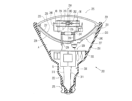
Figure 1 shows a HID integrated reflector lamp 200 having a sealed
20 reflector unit 225 received in a shell 250 enclosing a ballast 300. The reflector unit has a
glass lamp envelope 227 sealed in a gas-tight manner and enclosing a high pressure discharge
vessel 3.
The lamp envelope 227 includes a pressed glass reflector body with a
basal portion 229 and a parabolic surface 230 which extends to a rim 231 of the reflector
25 body. (Fig. 1) A cover in the form of a pressed glass lens 233 is hermetically sealed to the
reflector body at the rim 231. The parabolic surface 230 has an optical axis 234 with a focus
235 on the optical axis and has a reflective coating 237 thereon, such as ahlmin-lm, forming
a re~ective surface. Other suitable materials for the reflective coating inc}ude silver and
multi-layer dichroic coatings. The basal portion of the reflector body includes ferrules 239
30 through which conduclive supports 240, 241 extend in a gas-tight manner. The conductive
supports are connected to respective feed-throughs 40, 50 of the discharge vessel 3. The
discharge vessel 3 being arranged transverse to the optical axis 234. The conductive supports
also support a light Ir~n~mic.~ive sleeve 243 around the discharge vessel 3. The envelope 227
has a fillin of gas which in the absence of a properly sized sleeve would support convection
CA 02226467 1998-01-07
Wo 97/42651 9 pcTlls97loo5o6
currents during lamp operation. The light tr~n~missive sleeve 243 provides thermal regulation
by controlling convective cooling of the discharge Yessel 3.
The shell 250 is moulded ~rom a synthetic resin material which
with.~t~n~ls the operating temperatures reached by the sealed reflector unit and the ballast.
Suitable materials include PBT, polycarbonate, polyethermide, polysulphine and
polyphenylsulphine. The shell has a rim portion 251 which holds the outer surface of the rim
231 of the sealed reflector unit and provides a shoulder by which the lamp 200 can be
secured in a standard PAR fixture. A circumferential shoulder 253 provides a seat for a
corresponding flange 245 of the reflector body. The sealed reflector unil is secured by the
10 rim 251 with a snap fit axially against the shoulder 253. Opposite the rim portion, the shell
has a basal portion which receives a screw base 275. The screw base has a solder}ess
coMection with the input leads 310, 311 from the ballast 300. The shell includes a further
shouider 255 which suppor~s a circuit board 320 of the ballast. The shoulder 255 includes
tabs (not shown) which extend through respective holes in the circuit board. The tabs have
15 end portions which are pressed against the circuit board, by plastic welding for example, to
hold the circuit board against the shoulder.
The sleeve 243 and/or the lens 225 may be constructed to block UV light
emitted by the discharge vessel 3. The UV blocking function may be ob~ained through the
use of UV blocking glass, such as glass with an addition of cerium or tilanium~ or a UV
20 filter such as a dichroic coating. Such UV blocking glasses and filters are known in the art.
The filter may also be applied to the wall of the discharge device 3.
Additionally, the color of the light emitted bv the dischar~e device may
be altered by color correcting materials for the ceramic discharge vessel 3~ the sleeve 243 or
the lens 225 or with color correcting filters, such as dichroic filters, on these components.
The discharge vessel 3 is shown in more detail in Fig. 2 (not true to
scale). The discharge vessel is made of ceramic. i.e. it has ceramic walls. The discharge
vessel has a central zone forrned from a circular cylindrical wall 31 with an internal diameter
"ID" closed off at either end by end wall portions 32a, 32b, each end wall porlion 32a, 32b
forming an end face 33a, 33b of the discharge space 11. The end wall portions each have an
30 openin in which a ceramic closing plug 34, 35 is fastened in the end wall portion 32a, 32b
in a gas tight manner by means of a sintered joint S. The ceramic closin_ plugs 34, 35 define
opposing end zones of the discharge vessel and each narrowly enclose over a length I a lead-
through 40, 41; 50, 51 of an associaled electrode 4, 5 provided with a ~ip 4b, 5b. The lead-
throu h is connected to the closing plug 34, 35 in a vaS tight manner by means of a ceramic
CA 02226467 1998-01-07
Wo 97/42651 10 PcT/Isg7/00s06
glazing joint 10 at its side facing away from the discharge space.
The eleclrode tips 4b, 5b are siluated at a mutual ~ t~nre "EA". The
lead-throughs each comprise a portion 41, Sl being to a high degree halide-resistant made of,
for example, a Mo Al,03 cermet, and a portion 40, S0 which is fastened to an associated
5 closing plug 34, 35 in a gas tight manner by means of the ceramic glazing joint 10. The
ceramic glazing joint extends over some clict~nre, for example approximately 4 mm. The
portions 40, 50 are made of a metal which has a coefficient of expansion which harrnonizes
very well with that of the closing plugs. For example, Nb is a very suitable material. The
lead-through construction described renders it possible to operate the lamp in any burning
10 position as desired.
Each electrode 4, S comprises an electrode rod 4a, Sa which is provided
with a winding 4c, 5c near the tip 4b, 5b. The electrode tips lie adjacent the end faces 33a,
33b of the end wall portions. A further description of the discharge device and its closing
plug structure is available from U.S. Patent No. 5,442,609.
A starting aid 260 is secured to the discharge device 3 and consists of a
length of wire which has one end 261 connected to the lead-through 40. Its other end 262 is
a loop which extends around the opposing closing plug structure. In the area of the loop, the
closing plug structure has a gap between the portion Sl and the inner wall of the closing plug
35 in which the starting and buffer gas is present. When an ignition pulse is applied across
20 the lead-throughs 40,50, the leading edge of the starting pulse causes the star~ing and buffer
gas in the area of the loop 262 to ionize. This ionization provides free electrons as well as
UV light which generates further electrons that reduce the electric potential required for
starting.
25 Acoustic Resonance Protection
An important fea~ure of the integrated HID reflector lamp according to
the invention is the selection of the discharge vessel to have its lowest acoustic resonant
frequency (on a lamp current basis) at a frequency subsr~nti~lly higher than the audible
frequency of about 19 kHz. This provides a large frequency window in which the ballast can
30 operate above the audible range without the danger of inducing annoying flicker of the arc or
arc displ~rernent~ which lead to extinguishment or even failure of the discharge device 3.
In a ~lefell~d practical embodiment, the lamp according to Figure 1 was
constructed as a retrofit lamp to replace PAR 3B lamps used in, for example, high hat
fixtures for lighting cornmercial estabiichment~, such as the public areas of shopping malls.
CA 02226467 1998-01-07
WO 97/42651 1 1 PCT/IB97/00506
The discharge device has a rated power of 20 W. The discharge vessel is made of
polycrystalline aluminum oxide, has an internal ~ m~tPr ID of 3.0 mm and an interspacing
between the electrode tips "EA" of 2.0 mm. The closing plugs 34, 35 were sintered in the
end wall portions 32a, 32b substantially flush with the end faces 33a, 33b formed by the end
S wall portions. The electrodes have a ~lng~ten rod 4a, Sa provided with a t~-ng~tPn winding
4c, 5c at the tip 4b, Sb. The ~lict~n~e between each electrode tip and the ~ ent end face
was about 0.5 mm. In the pief~ d embodiment the ID was constant over the tlict~nce "L"
of 3.0 mm between the end faces 33(a), 33(b).
The discharge vessel has a filling of 2.3 mg Hg and 3.5 mg NaI, DyI3
10 and TII in a mole ratio of 90:1.4:8.6. The discharge vessel also contains Ar as a starting and
buffer gas. The interior of the sealed reflector envelope 227 has a gas fill of 75 % krypton,
with the balance N2 at a l~lessule of 400 Torr. The sleeve 243 has a wall thickness of 1 mm
and a clearance of ~ mm from the wall 31 of discharge device 3. In the disclosedembodiment, mercury is used as a buffer to fix the arc voltage at a level such that the lamp
15 is retrofit for the known incandescent reflector lamp. Other buffers may also be used such as
zinc and xenon.
The discharge vessel was found to have a lowest resonant frequency of
above 30 kHz (on a lamp current basis) during nominal lamp operat~on. There are two main
groups of acoustic resonances, the first being in the longitudinal (axial) direction of the
20 discharge vessel and the second being the azimuthal/radial resonances. It is desirable to have
the lowest resonant frequency for each group to be about the same, since the lowest one
determines the upper end of the operating window for the ballast. The longit~l~in~l
fi~n~s~mPn~l frequency is given by f,0 = C/(2*L) and the azimuthal/radial fund~ment~l
frequency is given by f,ro = 1.84*C/(7r*ID), where "L" and "ID" are the length and internal
25 ~i~mPter of the discharge space as shown in Fig. 2 and "C" is the speed of sound. The speed
of sound, however, is dependent on the temperature gradient of the gas in the discharge
space, and has been found to be different for the longit~l~in:~l and radial/azimuthal modes.
Based on exp~riment~tion~ the inventors have found that the speed of sound is approximately
420 m/s for the longit~ldin~l resonances and about 400 m/s for the azimuthal/radial
30 resonances for a discharge vessel with the above-described fill. For the specific 3 mm x 3
mm L:ID discharge vessel described above, fi0 = 70 kHz and f ro ~ 80 kHz (on a power
frequency basis). These correspond to 35 and 40 lcHz, re~eclively, on a current basis and
are regarded as being acceptably close together and subst~n~ ly the same. However, to
bring them closer together. the dimension ID can be made larger relative to the length L,
CA 02226467 1998-01-07
WO 97/42651 12 pcTlIs97loo5o6
which will lower the fundamental ~7imuth~1/radial frequencv towards that of the lon_itudinal
filnri~ment~l resonant frequency. This has resulted in that for a lamp according to the
invention the dimensions L and ID of the discharge vessel preferably satisfy the relation L c
ID S 1.2L.
Furthermore, it should be noted that the insertion depth of the electrodes
has little influence on the lowest acoustic resonance frequency, the insertion depth being only
a 2nd to 3rd order influence.
Because of this relatively large frequency window between the lowest
resonant frequency of the discharge vessel 3 and the audible frequency of 19 kHz, the ballast
may have a constant frequency during lamp operation, greatly simplifying its design and
cost. As further described below, for the above described discharge device, the operating
frequency for the filn(i~ment~l of the lamp current is selected at a nominal 24 kHz. This
provides a headroom of about 5 kHz with the lowest resonant frequency of 30 kHz of the
discharge device. Still a further aspect relates to controlling the amplitude of higher
harmonics of the fundamental frequency, to prevent acoustic resonance by such higher
harmonics. This aspect will be further fli~c-lssed in the following description of the ballast.
The Ballast
Figure 3 shows a block diagram of a high frequency lamp ballast for
operating the lamp of Figure 1. The ballast has input terminals I~ connected with input
leads 310, 311 to a rectifier circuit 110 providing a DC input to DC-AC inverter 120. A
resonant output circuit 130 is connected by conductive supports 240, 241 IO the discharge
vessel 3 of Figure 1 and is coupled to the DC-AC inverler. A control circuit 140 controls the
inverter 120 to ignite the lamp and to operate the lamp after ignition with a subst~nti~lly
constant lamp current frequency above about 19 kHz and below the lowest lamp resonant
frequency. The ballast includes a soft start circuit for generating a gradual increase in the
ignition voltage. A low voltage power supply (not shown) provides power to operate the
control circuit upon circuit slartup prior IO oscillation of the inverter as well as during
inver~er oscillation. A stop circuit 150 senses when the discharge vessel 3 has extinguished,
lurns off the inverler stage and turns it back on to provide a pulsing start to allow reignition
of the discharge vessel 3. The ignition pulses are provided for a nominal 50 ms, with a pulse
repetition frequency of a nominal 400 ms.
The inverter 120 is preferable a half-bridge inverter with MOSFET
switches connected in totem pole fashion. The OUtpUI of the half-bridge inverter, appearing
CA 02226467 1998-01-07
Wo g7/42651 1 3 PcT/Is97loo5o6
across mid points of the halfbridge inverter is a high frequency generally square wave signal.
The resonant output circuit 130 is of the LC-network type and includes
the primary winding of an inductor connPcte~ in series with a starting capacilor between the
midpoints. The resonant circuit is tuned to the third harmonic of the operating frequency
The discharge vessel 3 is connected electrically in parallel with the startin_ capacitor. The
LC network provides a waveshaping and current limiting function to provide a lamp current
to the discharge vessel 3 from the high fre4uency square wave output present across the half
bridge inverter midpoints.
The control circuit 140 controls the switching frequencv and pulse width
of the MOSFET switches to provide the lamp current to discharge vessel 3 at a substantially
constant frequency after }amp ignition.
During turn-on of the ballast an initial frequency is present of around 28
kHz. This effectively detunes the LC-network of the resonant output circuit 130 which has
been tuned to the third harmonic (about 72 kHz) of the nominal operatin frequency of about
24 }cHz. Thus, the MOSFET switches are turned on into a non-resonant condition, and the
current through these switches is significantly less than would be found at resonance. After
approximately 10 ms, the inverter frequency is shifted to ~he 24 kHz design range, which
ignites the discharge vessel 3.
The stop circuit 150 provides a pulse ignition voltage for 50 ms. The
stop circuit includes a switch Ql. When switch Q1 is conductive the low voltage power
supply is removed from the control circuits. Switch Ql is ultimalely controlled by the
presence of an over voltage on a secondary winding of the inductor. This may occur during
generation of the ignilion pulses if the discharge device does not ignite or if the discharge
vessel e~tinguishes during inverter oscillation. On an overvoltage across the secondary
winding causes the switch Ql is rendered conductive.
Lamp Efficacv: Pho~ometrics
The above described PAR 38 embodiment has a system wattage of 22 W,
with the lamp consuming about 20 W and the ballast having losses of about 2 W. Table 1
compares the photometric and colormetric parameters of this lamp (INV.) with that of a
comrnercially available 90 W Halogen PAR 38 and a 60 W PAR 38 with a halogen IR
burner. Also shown are the photometric parameters of two known blown glass reflectors, or
"R" lamps, an 85W VR40 and a 120W VR40. The data for the above-described lamps
CA 02226467 1998-01-07
WO 97142651 14 pcTlIs97loo~o6
according to the invention were based on a group of 20 samples. The light emitted by the
sample larnps had correlated color temperature (CCT) of 3000 K and a color rendering index
(CRI~ of > 85. The luminous efficacy of the lamp was 60 LPW. As compared to the known
60 W PAR 38 lamp with a halogen IR burner, the luminous efficacy was 233 % better, and
5 314 % better with respect to the 90 W halogen PAR 38. Additionally, the discharge device is
expected to have a life of about 10,000 hours, which is 3 to 4 times that of the known 60 W
halogen IR and 90 W halogen PAR 38 lamps.
TABLE I
I .AMP EFFICAC SPREAD CCT CRI
POWER LUMENS Y (Flood)
(LPW) Degrees K
(W)
iNV . 22 1320 60 28 3000 85-87
90 W 90 1280 14.5 28 2900 100
60 W ~R 60 1100 1~ 29 2800 95
85WVR40 85 925 10.9
120WVR40 120 1150 9.6
Accordingly, it is clear that the integrated lamp is superior to the
commercially available halogen and halogen IR PAR lamps and the incandescent blown glass
20 reflector lamps with respect to life and luminous efficacy. Additionally, by altering the fill of
the discharge device with known metal halide technology, the lamp designer has greater
control over the photometric pararneters as compared to a lamp generating light with an
inr~n~escen~ fil~mrnt, in particular with respect to the correlated color temperature.
A siEnific~nt advantage of the use of a metal halide discharge device with
25 a ceramic wall, and at low wattages, is the significant colorimetric uniformity (a) relative to
burning position and (b) from lamp-to-lamp. This uniformity is believed to be due to the
small physical size which leads to more uniform thermal properties in the lamp fill during
operation and the tight dimensional controle to which the ceramic material can be held during
CA 02226467 1998-01-07
W O 97/42651 rCT~B97/00506
high speed m~nllf~tllnng, which provides the lamp-to-lamp uniformity. It has been found
that c~r~mic discharge vessel ~imensions can be held to better than 1% (six sigma) whereas
for convention~l quartz arc tube technology the ~im~ncions can only be held to about 10%.
Figure 4(A) and 4(B) are graphs of CCT and CRI, respectively, for a
S typical low wattage ce~mic metal halide (CDM) lamp and a typical quartz metal halide lamp
as a function of burning position, intli~t~d as degrees from the vertical, base up (VBU)
burning position. For CCT, the CDM lamp had only a variation of 75 K versus a v~ tio~
of about 600 K for the quartz lamp, over the range 0-90 degrees from VBU. Likewise, for
CRI, the CDM lamp had a variation of only about 2.5 CRI versus about 10 CRI for the
10 quart~ metal halide lamp.
Additionally, with respect to lamp-to-lamp color stability, a low wattage
metal halide with a ceramic discharge vessel typically exhibits a standard deviation of 30 K
in color temperature. For low wattage metal halide lamps with quartz arc tu~es, the standard
deviation is much greater, 150 - 300 K. The much narrower spread in coior ~e.-.p~l~ture is
15 illlpo~ t because it makes the integrated lamp with the ceramic metal halide discharge
device an acceptable replacement for halogen PAR lamps for indoor and retail li~hting. In
effect, when many reflector lamps with the ceramic discharge device are used, for Px~mple
in a ceiling, they will appear to be subst~nti~lly ~mifo~ , unlike quartz metal halide lamps in
which the observer would clearly notice the non-uniformity among the lamps.
A critical aspect of the integrated lamp according to the invention is that
these improvements were achieved in an overall outline which substantially fits within that of
the outline for the cG.lc~onding lamp type; in the embodiment shown within the ANSI
specifi~tion for a PAR 38 lamp. This allows the integrated PAR 38 HID lamp to be retrofit
into all fixtures deciEn~d to physically accept a conventional PAR 38 lamp. Figure 5 shows
the outline of the lamp of Fig. 1 superimposed over the ANSI specified outline for a PAR 38
lamp. The rlim~nciQns (mm) are: Pl=135; P2=135; P3=28.2; P4=40.4; PS=26.8; P6=
48.8 and P7=540.
Several features f~rilit~t~ this pack~EinE. The first is the use of small,
compact HID light source having a small overall length. The overall length of the 20 W arc
tube was 22 mm. The small overall length permits the arc tube to be pocitiorled transversely
with respect to the optical axis within a reflector body which is nested in an outer shell
having a m~rimum rim ~i~mPt~r within that of the ANSI sperifi~tion. In this PAR 38
embodiment, ~he sealed reflector envelope 227 is a PAR 36 envelope and has an inside
meter measured at the rim 231 of 96 mm. The outside ~i~mesPr is about 110 mm. The
CA 02226467 1998-01-07
WO 97/42651 PCTIIB97/00506
16
transverse mounting also perrnits the use of an axially shallow reflector body, leaving
s~ffioj~nt room for the ballast.
The use of a pressed glass reflector body with a co~ ~dtively thick rear
wall in conjunction with the reflective coating on the rear wall provides acceptable t~
5 in~tll~tion, preventing excessive heating of the ballast by radiant energy from the ~ harg~
device. In this case, the minimllm thirknes~ of the reflector body at the basal portion was 3
mm. Ad~ ion~l thermal protection is provided by the outer periphery of the circuit board
being tightly seated against the shoulder 25~, which effectively retards air circulation from
the warmer first colnpalilllellt "A" ad~acent the reflector to the second colllp~llllent HB"
10 between the circuit board and the base. Temperatures measured in the interior of the shell
dunng base-up operation were s~lffi~iently low so as to ensure a circuit life comparable to
that of the discharge vessel 3. Generally, the maximum circuit telllperdtures should be below
100~ C. In the lamp described above, the telllpe.ature measured at the reflector side of the
circuit board 320 was 83~ C while the ~e~npel~ture on the ballast component side was 75~ C.
15 The air tellll,~ldture in the colllp~lllent B between the circuit board and the shell at the
ballasts side was 74~ C. The highest circuit component te"-l,elatllre was 81~ C.The thermal regulation of the discharge vessel 3 within a gas filled, thick
walled pressed glass envelope and surrounded by a sleeve aids in controlling photometrics,
which allows a greater range of ambient conditions in which the lamp can be operated
20 without the photometrics noticeably shifting.
The small physical size of the discharge vessel, along with the L:ID
~im~nsionS on the order of 1:1, was also important for reducing the size of the ballast. Since
the discharge vessel has a lowest acoustic resonant frequency at about 30 kHz on a current
basis, there is a sllfficient window in which the ballast can operate above 19 kHz and at a
25 constant frequency during lamp operation. High frequency operation is illlpoll~nt because it
provides reduced physical size of the inductive ~l~mPnt~ of the ballast. Operating at a fixed
frequency provides simple control of the ballast inverter, thus redu-ing size (and cost).
In Figure 1, the discharge vessel 3 is in a gas filled envelope 227 sealed
to cover 233 surrounded by a quartz glass sleeve 243 supported by straps connected to the
30 leads 240, 241.
A primary reason that the envelope 227 is sealed is to protect the leads
40, 50 and 240, 241 from oxidation. Instead of a glass bonded seal at the rim 231, a less
than herrnetic seal, such as an epoxy seal could be used if the leads are protected with an
anti-oxidation coating.
CA 02226467 1998-01-07
WO 97/42651 PCT/IB97/00506
17
Additionally, with adequate thermal control, an HID reflector lamp
fitting within the outline of a corresponding lamp may also be obtained with a reflector body
of other than glass, such as for ex~mple a high te...~dture plastic with a reflective coating,
such as, for Py~mple, of ~ min~lm or silver deposi~Pd thereon, or applied, for example, as a
5 my~ar sheet. The reflector body/surface may form an integral part of the shell.
Figure 6(A) shows a mount construction for a plurality (in this case two)
of discharge vessel 3(a), 3(b) ~l~ctri~lly in series within a reflector body, such as shown in
Figure 1. Components co~lt;~onding to those shown in Figure 1 have the same reference
numbers. The discharge vessel 3(a) has one lead 40(a) fixed to lead 240 while vessel 3(b) has
10 one lead 50(b) connected the other lead 241. The series connection is completed by
conductive element 403 bridging leads 50(a) and 40(b) of the discharge vessels 3(a); 3(b).
The çl~ nt~ 401, 402 are non-conductive and provide additional merh~nic~l support. The
ignition aid 260 is not shown for purposes of clarity. With two discharge vessel operated
concurrently, the lamp provides approximately twice the light output. Each discharge vessel
15 has its lowest resonant frequency above 30 kHz, so with the ballast providing larnp current at
a nominal 24 kHz, there is no danger of inducing acoustic resonance. It should be noted that
a single discharge vessel having a rated wattage of 40 W, the same as the two 20 W
discharge vessels, would have its lowest lamp resonant frequency cignific~ntly lower than
that for each of the two 20 W discharge vessels, either much closer to 19 kHz or below 19
20 kHz. Accordingly, by using two discharge vessels the large resonance free operating window
above about 19 kHz is retained while the benefit of more light output of a higher wattage
larnp is obtained. While two discharge vessels zre shown, concurrent operation of more than
two discharge vessels is possible, so long as the circuit is modified to provide the correct
i~nition and operating voltage for the lamp. Other ignition aids, such as a well known W~5 enh~nrPr, may alternatively be incorporated in the larnp to improve ignition char~- tericti~s.
Figure 6(B) shows a mount construction for a pair of discharge vessels
3(a~, 3(b) connected electric~lly in parallel. In this case, the leads 240, 241 have respective
conductive cross-bars 240(a), 241(a) electrically connected to respective ones of the leads
40(a), 40(b); 50(a); 50(b) and m~ ch~nic~lly supporting the discharge vessels 3(a), 3(b). Such~0 a parallel arrangement effectively doubles the life of the lamp, since only one
discharge
- vessel will ignite and generate light due to the slight differences in impedance between the
discharge vessels. At the end of life of one discharge vessel, the other one will take over.
Th~s also provides instant restrike capa'oility. If the operating discharge vessel extinguishes
because of a power interruption, for example, its impedance due to its elevated te~pe~dture
CA 02226467 1998-01-07
WO 97/42651 18 PCTlIs97loo5o6
may be sufficiently high so as not to ignite. However, the other discharge vessel ~ hich was
not previously operating will have a significantly lower temperature and will readily ignite.
An advantage of DC operation is the complete avoidance of acoustic
resonance and its simplicity. However, a disadvantage is that the discharge device operated
5 on DC is more sensitive to changes in color with changes in operating position and is
sllsceptible to salt migration.
HID lamps with cerarnic discharge devices are shown and described with
respect to Figure 1 have shown acceptable colorimetric and photometric out throu_h S000
hours of operation.