Note: Descriptions are shown in the official language in which they were submitted.
CA 02226682 1998-01-13
- W O 97/25125 PCT~US97/00280
~THOD AND APPARATUS FOR REMOVAL OF HAZARDOUS
GASES FROM ENC~OSED STRUCTURES
This invention relates to a method and apparatus for
scrubbing gases, or stripping liquids, containing
hazardous materials such as ethylene dichloride and
hydrogen sulfide from the enclosed confines of storage
tanks or other vessels, and more particularly to such a
method and mobile apparatus for rendering these enclosed
spaces safe for human entry without extraneous safety
equipment while preventing contamination of the
environment.
Petroleum products, particularly crude oil, are
stored in tanks, many of which are very large, holding as
much as 500,000 barrels of crude oil. Such tanks may
exceed 250 feet in diameter. Crude oil stored in these
tanks deposit sludges which accumulate on the bottom of
the tanks, resulting in operational problems and
~; m; n; she~ volumetric capacity. Several methods have
been devised to agitate or circulate the contents of the
tanks, simplify the cleaning of these tanks and the
removal of accumulated sludges from the tanks. For
example, such methods and equipment are described in U.S.
Patents 4,945,933, 4,817,653, 5,091,016, 5,460,331 and
4,407,678. While each of these patents describes
successfu:L means for handling the sludges in various
ways, anol_her problem has existed with respect to sour
crude oil storage that is not addressed by any of the
aforement:ioned art and, yet, creates an extremely
hazardous situation for ultimate cleaning of storage
~ tanks, requiring the entry of work people into the tanks.
This prob:Lem is the accumulation of dangerous hydrogen
sulfide gas and for carcinogen benzene vapors in the
CA 02226682 1998-01-13
W O 97/25125 PCT~US97/00280
.
tank.
An environmental concern has also developed in
connection with soils contaminated with volatile
hazardous chlorinated hydrocarbon gases, such as ethylene
dichloride. Often the only solution for containment of
the solids contaminated with ethylene dichloride in a
benign manner is by using an enclosed storage tank as a
holding vessel for such contaminated soils. As the soil
lies in the tank, the volatile ethylene dichloride
permeates the atmosphere within the tank, creating a
dangerous situation of proportions equal to that of the
hydrogen sulfide invasion of the contained atmosphere of
a hydrocarbon storage tank.
Additionally, the entry of a worker into an
atmosphere of ethylene dichloride requires care e~ual to
that of the care required in an atmosphere invaded by
hydrogen sulfide. Many attempts have been made to avoid
the necessity of entry into such tanks which burdens the
worker by the necessity of wearing heavy, hot and
cumbersome equipment to the extent that efficiency is
lost and dangerous, life threatening work situations
occur, particularly in the enclosed tank atmosphere
during hot periods, such as summer along the Texas and
Louisiana Gulf Coast where many such tanks exist.
Because of continued governmental regulations, such
as the United States Resource Conversion and Recovery Act
(RCRA) and the United States Hazardous and Solid Waste
Amendment of 1984 (HSWA), which establish comprehensive
"cradle to grave" provisions to regulate hazardous
materials, there is an increased need of the efficient
CA 02226682 l998-0l-l3
W 097/25125 PCT~US97/OQ280
removal of volatile compounds from solid materials and
enclosed environments.
The ethylene dichloride problem is particularly
troublesome since it is a material which, when
contaminating soil, must be removed but, without adequate
means of cont~;nm~nt, becomes a complicated environmental
problem. ~oil contaminated with ethylene dichloride also
presents a threat to the water supply. Since benzene,
ethylene dichloride and the chlorinated hydrocarbons are
somewhat water soluble, they leach ~rom surface soil into
progressively deeper areas of soil and ultimately end up
in lakes and streams. Therefore, the contamination to be
contained must be separated from the possibility of
leaching caused by natural circumstances such as rain and
weather. However, when so protected by putting it into
closed containers, such as large storage tanks, the vapor
pressure of VOCs and ethylene dichloride at elevated
temperatures increases to the point where the entire
atmosphere within such storage vessel is, in short time,
permeated. with the hazardous gas mixture.
Further, the captivity of such hazardous gases
within th.e vapor atmosphere of such storage tanks creates
a hazard in the neighborhood of such tanks because of the
expansion. and contraction of gases with changes in
ambient temperature. A temperature rise causes the gases
to exit through vents into the surrounding area and,
while attempts are made to contain such exposure to
gases, su.ch as hydrogen sulfide and ethylene dichloride,
through a.bsorption in carbon canisters on such vents,
high concentrations of such materials quickly saturate
CA 02226682 l998-0l-l3
W O 97/25125 PCTAJS97/00280
the carbon bed and cause breakthroughs into the
surrounding area creating hazards of health and fire for
even a slightly careless act.
one aspect of this invention is to provide for the
removal of hazardous gases from the interior of closed
vessels, particularly storage tanks, without re~uiring
the entry of workers into the vessel and without causing
atmospheric contamination.
The present invention, therefore, provides a method
for capturing hazardous gases having water solubility
from cont~inment vessels including the steps of
withdrawing hazardous gases from the vessel, introducing
the gases into lower regions of a scrubbing zone,
contacting the rising gases with sufficient water in
counter-current flow to capture such hazardous gases in a
water stream and create a gas stream having a
substantially reduced content of hazardous gas, recycling
the gas stream to the vessel to sweep additional
hazardous gases from the vessel, withdrawing the water
stream and dissolved hazardous gases from the scrubbing
zone, diluting the water stream with additional water to
create a recycle stream having a lowered concentration of
absorbed hazardous gases and a bottoms stream, returning
the recycle stream to the scrubbing zone, and removing
the absorbed hazardous gas from the bottoms stream for
disposal.
The present invention is also directed to overcoming
the problems set forth above by providing an apparatus
for effectively removing undesirable, water soluble
compounds from a gas, without requiring the entry of
CA 02226682 1998-01-13
W O 97/25125 PCTAUS97/00280
workers into a vessel in which the gas is contained. It
is also desirable to have such an apparatus that is
mobile, and can be moved from site-to-site, as needed, to
remove contaminate materials from the enclosed
environment of a storage tank. Furthermore, it is
desirable to have a mobile apparatus capable of
separating water soluble hazardous materials from a
gaseous mixture enclosed within a storage tank, and then
recirculating the cleaned gases to the tank to sweep
additional hazardous materials from the tank
The present invention is, therefore, also directed
to a mobile apparatus for promoting gas/liquid mass
transfer, including a mobile frame, a tower containing a
packed b~ed pivotally mounted on said mobile frame for
movement between a horizontal transport position to a
vertical operating position, said tower having an upper
end portion and a lower end portion when disposed at said
vertical operating position, means for moving said tower
between said horizontal transport position and said
vertical operating position, means for maintaining said
tower at said vertical operating position, means for
receiving and distributing gas upwardly through said
tower when the tower is in said vertical operating
position, and means for receiving and distributing water
downwarclly through the packing of said tower when the
tower i~l in said vertical operating position.
Further features and advantages of the invention
will bec:ome more apparent from the following description
taken in conjunction with the accompanying drawings,
wherein:
CA 02226682 1998-01-13
W O 97/~5125 PCT~US97/00280
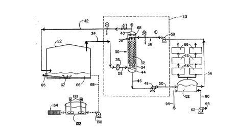
Fig. 1 is a schematic flow diagram showing in
schematic form the preferred embodiment of the method of
this invention with gauges, valves and fittings not
shown. Also, this drawing shows, within the area defined
by broken lines, the principal elements of the mobile
apparatus embodying the present invention in which
hazardous gases are removed from enclosed structures;
Fig. 2 is a perspective view of a mobile apparatus,
defined within the area enclosed by broken lines in Fig.
1, representing a preferred embodiment of the present
invention;
Fig. 3 is a side elevation view of the mobile
apparatus of the preferred embodiment of the present
invention, showing the scrubbing tower in a horizontal
traveling position and, in broken lines, in a vertical
operating position;
Fig. 4 is a side view of the scrubbing tower and the
cradle which support the scrubbing tower;
Fig. 5 is a sectional top view of the tower cradle
taken along the line 5-5 in Fig. 4;
Fig. 6 is a cross-sectional view of the scrubbing
tower and its supporting cradle taken along the line 6-6
in Fig. 4;
Fig. 7 is a cross-sectional view of the scrubbing
tower and the supporting cradle taken along the line 7-7
in Fig. 4;
Fig. 8 is an enlarged detailed sectional view of the
tower side support structure, taken from the dashed
circle 8 in Fig. 7;
Fig. 9 is an enlarged detailed schematic view of the
CA 02226682 1998-01-13
W O 97/25125 PCTAUS97/00280
cylinder connection portion of the pivot arm used to lift
the scrubbing tower, taken from the dashed circle 9 in
Fig. 4; and
Fig. 10 is a cross-sectional schematic view of the
cylinder connection of the pivot arm taken along the line
10-10 of Fig. 9.
This invention relates primarily to the
decontamination of the interior headspace of vessels
containing a hazardous gas atmosphere which includes
gases which have water solubility, particularly hazardous
chlorinated hydrocarbons and, especially benzene,
hydrogen sulfide or ethylene dichloride, which permeate
the area of inside of storage tanks and, if allowed to
invade the atmosphere surrounding such tanks, create a
condition ha~ardous to people in the vicinity of the
tank. A number of chlorinated hydrocarbons are volatile
and, at the same time, soluble to some extent in water.
These gaCes often find their way into the environment
through a spill or leak of one kind or another. Since
they have water solubility, they may be transported into
an aquifer and subsequently into drinking water. They
often are also volatile and, thus, become part of the air
pollution problem if they remain unchecked.
Consequently, a spill or contamination of soil of this
nature must be physically scooped up and placed in a
container, often an empty hydrocarbon storage tank.
Since the chlorinated hydrocarbon and, especially
ethylene dichloride, may be volatile and since tanks are
subject t:o wide ranges of temperatures by virtue of the
sun's impact upon their skins, a cont~m;n~ted atmosphere
CA 02226682 1998-01-13
W O 97125125 PCTAUS97/00280
'
is created inside of the storage vessels or tanks, which
atmosphere is dangerous and difficult to abate. Of
course, the tank cannot become permanent storage for this
contaminated soil. In the broad sense, this invention is
a method to clean the atmosphere inside storage tanks to
permit entry by workers in order to clean the tank. In a
specific sense, the process of this invention is a method
to reduce the danger of soil contaminated with
chlorinated hydrocarbons, especially ethylene dichloride
to allow the proper disposal of such soil in a permitted
land fill. To be effective, this method requires that
the hazardous gas have water solubility. It does not
have to be infinitely water soluble, but the scrubbing is
carried out with water and, therefore, to be operable,
requires water solubility. For example, the removal of
ethylene dichloride, hydrogen sulfide and benzene have
sufficient solubility to allow economic operation of the
method.
The description of the method of this invention
which follows is better understood by reference to the
flow diagram shown in Fig. 1 as examples of an embodiment
of the invention described herein. The description which
follows includes in it the best mode for practicing the
invention known to the inventors. It will illustrate
both the evacuation of the interior headspace of a vessel
using a storage tank as the exemplary structure, either
from the vaporization of stored sour crude oil or through
the removal of ethylene dichloride from soil.
The gaseous atmosphere being treated in the process
of this invention is captive in the headspace of a
CA 02226682 1998-01-13
W O 97/25125 PCTAUS97/00280
.
cont~inmPnt vessel shown in Figure 1 as storage tank 22.
A mobile mass transfer apparatus 20 embodying the
apparatus of the invention includes the components
enclosed within the dashed line in Fig. 1 will be further
described later. In the embodiment where a crude oil
storage tank is being decontaminated, the hazardous gas
the tank atmosphere would normally be hydrogen sulfide
and to a lesser extent, benzene. Where ethylene
dichlori~e contaminated soil is involved, the hazardous
gas is e~hylene dichloride. The gas within the
atmosphere of storage tank 22 is removed through line 24
to a blower 26 which places a suction on tank 22, thus
reducing the interior pressure o~ the tank to below
atmosphe:ric pressure. The size and make of the blower 26
is a matter of engineering choice.
In an illustrative embodiment, the blower 26 is a
Dresser Industries, Roots Division, Model RGS-JV size 624
driven by a 75 horsepower diesel engine. The blower 26
preferably operates at a variable speed for ~rom about
1100 to about 2100 rpm. Smaller blowers, such as the
Model RAIU size 718 blower, are also available and,
depending on the desired gas flow rates, also may be used
in the present invention. I~ stripping a hazardous or
volatile organic compound from water the inlet of the
blower may draw in fresh or ambient air or another gas.
~ epending upon the size and capacity o~ the blower,
a vacuum can be drawn on the tank to the extent of
several inches of water with the preferred amount being
about -l psig. A preferred range would be from about 0.5
to about 2 psig negative pressure. To affirmatively
CA 02226682 l998-0l-l3
W O 97/25125 PCT~US97/00280
protect the surrounding vicinity of the vessel, a
subatmospheric pressure must be maintained. It should be
sufficiently below atmospheric pressure to accommodate
temperature fluctuations. Of course, a normal storage
tank could collapse with the drawing too great of a
vacuum on the tank. This negative atmosphere
accomplishes the purpose of maintaining a safe atmosphere
in the environment surrounding tank 22 to prevent the
hazardous gases from exiting through the vent system of
the tank (not shown) which occurs when the pressure
inside the tank exceeds that of the atmospheric pressure
outside tank 22.
The vapors from the atmosphere of tank 22 passing
through blower 26 creates a contaminated gas stream which
enters line 28 at a superatmospheric pressure of from 3
to about 6 psig, preferably from 4 to 5 psig, and is
conducted from there to a scrubber 30 where it is
introduced into lower regions of the scrubbing zone 32 at
the lower end of scrubbing zone 32 through a means for
distributing the gas at the bottom of scrubbers, such as
a perforated pipe distributor or sparger 34. The vapors
containing the hazardous gas flow upwardly through the
scrubber 30, preferably through water-flooded packing P
to contact, in counter-current flow, water entering the
upper part of scrubber 30 through line 36 and appropriate
distributors 38 to uniformly flood packing P. The
distributor 38 may be any such structure well known to
the skilled engineer, such as, for example, trays, wire
boxes or spray nozzles. The gases entering the scrubber
30 are allowed to expand on entering the scrubbing zone
CA 02226682 1998-01-13
W O 97/25125 PCT~US97tW280
32, thus causing the gases to cool somewhat and
increasing the solubility of such gases in the scrubbing
water flowing through packing P.
Although a mobile scrubbing tower has been employed
in the practice of this invention as a way of keeping the
environment around storage tanks clear of hazardous gases
and fumes, the scrubber 30 may be designed as a permanent
installation connected to a plurality of storage tanks
creating subatmospheric pressure in several of them while
continually collecting hazardous gases as they are
released within the tanks themselves, where the cleanup
problem reoccurs with such fre~uency that a permanent
installation is justified.
The solubility of chlorinated hydrocarbons (and
other hazardous gases) in water is available in readily
available handbooks. Ethylene dichloride has a maximum
solubility at 2~~C of one part by weight per 128 parts by
weight of water (about 8~ by weight). This is calculated
by the saturation of its water, the ratio of water/gas
can be calculated. At lower temperatures, the solubility
is greater, resulting in more efficient removal of
ethylene dichloride from the gas stream. Thus, the
comparable flow rates and residence time can be easily
calculated and adjusted by the skilled engineer to
provide sufficient contact to remove the ethylene
dichloride. In the operation of the method of this
invention,, of course the exiting vapors have
- substantially reduced content of hazardous gas, here
ethylene dichloride, but will contain some ethylene
dichloride, depending upon the amount of water contact
.
CA 02226682 1998-01-13
W O 97/25125 PCT~US97/00280
and the temperature of the contact. During scrubbing
operations the water level in the tower is preferably
maintained at a level of from about 10~ to about 60~ of
the scrubber height, preferably from 25~ to 50~. In the
practice of this invention, it is not necessary to remove
all of the ethylene dichloride from the vapor where the
vapor is returned to the tank. If not returned, carbon
canisters may do the polishing. The flow rate of the
water entering scrubber 30 through line 36 is from about
100 to about 300 gallons per minute and, preferably, from
about 225 to about 275 gpm. ~f course, this will vary
with the design size of the scrubber 30 and the loading
of the vapors entering the scrubbing zone 32. The water
and entering gas stream create an internal pressure
within the scrubber from abut 1.8 psig to about ~ psig,
preferably from about 2 to about 3 psig.
This contact with the scrubbing water removes the
hazardous water soluble gases such as ethylene dichloride
or hydrogen sulfide~from the vapor stream resulting in
vapors collecting in the headspace 40 of the scrubber 30,
having substantially lowered content, if not
substantially free, of hazardous gases. From the
headspace 40 the vapors may be vented through a
collection device to remove the residual hazardous gas
from the vapors such as, for example, carbon canisters,
but preferably the vapors are recycled back to tank 22
through line 42. The recycled vapors then sweep more
hazardous gases from tank 22 into line 24 and the cycle
continues until tank 22 is safe for entry. Where a
contaminated soil is the source of atmospheric
CA 02226682 l998-0l-l3
W O 97/25125 PCT~US97/00280
contamina.tion the cycle continues until the soil washed
in the tank releases no more ethylene dichloride. Fresh
outside air could be used to sweep tank 22 and vent the
vapors to the atmosphere after complete ethylene
dichloride removal through carbon canister but the
recycle gas sweep is preferred. Removal of the ethylene
dichloride from water using the carbon canister is much
more convenient than from a gas stream, primarily due to
the size of the canister.
The water circulating through the packing P of the
scrubber 30 in the scrubbing zone 32 becomes contaminated
with the condensed and absorbed hazardous gases and
collects in the bottom 44 of scrubber 30. The
contaminated water stream proceeds from the bottom 44 of
scrubber through line 46, pump 48 and line 50 to a
holding vessel 52 which is, of course, isolated from the
atmosphere because of the volatility of the hazardous
gases absorbed in scrubber 30. In holding tank 52, a
stream of feed water enters holding tank 52 through line
54 to dilute the contaminated water entering through line
50. The dilution reduces the concentration of the
hazardous gas in the water stream making it useful to
absorb additional hazardous gases in scrubber 30 when
used, in the preferred manner, as a recycle stream. The
water entering through line 54 into holding tank 52 may
be used to adjust the temperature of the water being
circulated in the system over the scrubber 30, since
- lower temperature water will absorb more ethylene
dichloride and hydrogen sulfide. Such temperature
adjustment depends, of course, upon the overall operation
CA 02226682 l998-0l-l3
W O 97/25125 PCT~US97/0028
14
of the process and the temperature of the source of
dilution water. ~ost often, the temperature of the water
and, indeed, the entire system will be dictated by the
ambient temperature and, thus, in the summer, in the
Northern Hemisphere, of course, the water circulated and
the gas treated would be at a higher, nearly ambient
temperature. The flow rates would, o~ course, then be
adjusted to accommodate the temperature.
This recycle stream, diluted to approximately 1/4 to
2/3 the concentration of the entering contaminated water
stream through line 50 is removed ~rom holding tank 52 as
a purge stream through line 56 sent through a second pump
5~ at the aforementioned flow-rate and conduit 36 to the
scrubber 30. The balance of the diluted water is removed
from holding tank 52 through line 60, a third pump 62 and
line 64 to carbon cartridge filters (not shown) where the
hazardous material, whether ethylene dichloride or
hydrogen sulfide is absorbed ~rom the water onto carbon
cartridges. Preferred filter cartridges are supplied by
Calgon and are well known to those skilled in the art.
The sizing of such cartridges, usually installed in
parallel in order to allow for replacement when fully
charged without shutting down the entire system, is
within the ordinary skill of the engineer.
The dilution of the contaminated water stream
entering holding tank 52 through line 50 protects the
carbon cartridges from being consumed at a rapid rate.
Holding tank 52 must be protected against the escape of
vapors by the installation o~ carbon filter 66 on the
tank vent to absorb the hazardous gases which may be
CA 02226682 1998-01-13
WO 97/25125 PCTrUS97/00280
released into the vapor phase. One or more carbon
~ilters 66 are placed in series and parallel in order to
prevent an accidental contamination to the atmosphere.
As a safety precaution to protect against reaching an LEL
condition in the vapors of tank 52, nitrogen gas was
directed into the tank at a rate of from about 2 to about
6, but preferably, about 4 cubic feet per minute to
dilute the ethylene dichloride level. This also extended
the life of the carbon canister.
Often the gas contaminating the space of a vessel
will be resulting from solids which have collected as
residue inside the vessel, particularly in the case of
storage tanks, or in the case of containing in such a
tank contaminated soil resulting from a spill of a
hazardow, material. In the embodiment of our invention
which in~olves not only the removal of hazardous gases
from the vapor space in a tank, but the cleansing of
contaminated solids in the tank, it is important to use
some agitation or dilution of the solids in the tank in
order to free noxious gases for removal and recovery as
part of the tank cleaning. This occurs when there is a
storage tank with a heal of heavy hydrocarbons or where
the soil is contaminated wlth chlorinated hydrocarbons,
particularly those that are water soluble and much more
particularly, ethylene dichloride, specifically.
In the case where tank 22 is an oil storage tank,
the sludge can be agitated in ways known to those skilled
in the art, for instance, as described in U.S. Patent
4,407,678, which is incorporated herein by reference for
all purposes. The tank may be permanently ~itted with
,
CA 02226682 l998-0l-l3
W O 97/25125 PCT~US97/00280
_--.
16
dispersion apparatus as described in U.S. Patent
5,460,331, also incorporated herein by reference for all
purposes. As shown in Fig. 1, (sludge) soil 66 is mixed
and slurried with water which causes the contAm;n~t to
be released from the soil into the water to saturate it
and from there lnto the atmosphere in tank 22. Where the
contaminated soil has resulted from a spill, there may
even be instances where the contAmin~nt is floating on
the saturated water thereby creating a maximum
concentration in the tank. Additional water must be
added to accomplish the removal. Part can be removed by
removing the slurry itself. The slurries are removed
through line 68, pump 130 to a holding tank 132. There
it is agitated by mixers 133 and, thence, the solids are
separated by appropriate separation means shown as filter
press 134. Of course, other known means for separation
o~ solids and li~uids, such as centrifuge and the like,
are well known.
Other means o~ cleaning sludge from storage tanks
are known and described in U.S. Patents 4,817,653,
4,945,933 and 5,091,016, for example, all of which are
incorporated herein by re~erence for all purposes.
If tank 22 contains a soil contaminated with
ethylene dichloride to be cleaned to allow disposal, then
water is introduced through line 65 to an agitation means
67, the operation of which is more specifically disclosed
and described in U.S. Patents 4,945,933 and 5,091,016,
which are incorporated herein by reference for all
purposes. In this instance, the use of the agitation
means 67 causes the ethylene dichloride contamination on
CA 02226682 1998-01-13
W O 97/2~12~ PCTrUS97/00280
the soil to be freed from the soil into the water and
then to permeate the atmosphere within the tank 22 with
ethylene dichloride or to become dissolved in the water
up to the level of solubility at the given temperature.
Thus, the soil becomes substantially cleaned and then
withdrawn in the form of a slurry having 2 to 3 parts by
volume of water per part of solids in the slurry. It is
withdrawn through line 68, pump 130 and, thence, into
holding tank 132, where agitation is maintained with
stirrers 133. Evaporation again occurs in an appropriate
solids liquid separation device with the vapors being
trapped ;~nd conveyed back into tank 22 directly or into
the system hereto~ore described. The solids are now
su~iciently free of any ethylene dichloride to be
removed to the environment for disposal as a solid waste
in a permitted site. The liquid having minor ethylene
dichloride contamination r~; n; ng iS either polished by
passing through a carbon canister, not shown, or
transmitted to the holding tank 132 for mingling with
other contaminated water streams resulting from the
practice of this invention.
In Fig. 2 the blower 26, first pump 48 and second
pump ~8 are shown in their preferred embodiments as
mounted on the mobile frame shown as a flatbed trailer 70
it being understood, however, that one or more of these
pieces may be separately mounted and transported to the
area wherein the scrubbing apparatus of this invention is
- used. The determination of which, if any of this
equipment is mounted on the mobile frame, is an option
but the preferred embodiment shown in Fig 2 carries the
CA 02226682 l998-0l-l3
W O 97/25125 PCT~US97/00280
_'
18
entire apparatus as a distinct unit. Desirably, a
removable suction filter 25 is located on the inlet side
of the blower 26. The suction filter 25 is used during
operations as a stripping tower but is not generally
re~uired during closed loop circulation, and therefore
may be removed during such operation and the inlet line
24 coupled directly to the inlet port of the blower 26.
EXAMPLE
A fixed-roof crude oil storage tank 22, having a
diameter of llO ft. was used in this example. The tank
22 had an accumulation of about l l/2 feet of soil and
water contaminated with ethylene dichloride in the
bottom. The atmosphere within the tank 22 was
contaminated with well over l,000 parts per million of
ethylene dichloride. The mobile scrubbing apparatus 20
embodying one aspect of the present invention was placed
adjacent the tank 22 and the lines 24 and 42 were
connected with the interior of the tank 22. The
scrubbing zone 32 of the scru~bing tower 30 was packed
with 3 l/2 inch diameter hollow spherically shaped
packing made of in~ected molded plastic (JAEGER TRI-PACS,
Jaeger Products, Inc., Spring, Texas) to a depth of 19.7
feet. Tanks 52 and 132 were covered portable tanks
normally used to contain oil well fracturing materials,
frac tanks, fitted with carbon pack absorption units to
clean any vapors escaping from such portable tanks. The
water level in the storage tank 22, containing the soil,
was raised from l ft. 8 in. to 3 ft., with the water
entering through the supply line 65 and the agitator 67,
thereby causing intermixing of the water and the ethylene
CA 02226682 1998-01-13
W O 97/25125 PCTAUS97/00280
.
19
dichloricle soil and causing the ethylene dichloride to be
released ~rom the soil and dissolved in the water. Water
circulation was started at a rate of about 240 gpm in the
loop through the scrubber using pumps 58 and 48. The
liquid level in the scrubbing tower 30 was maintained at
about one half the height of the scrubber. The vapor
blower 26 was started and the contaminated gas atmosphere
in the storage tank 22 was withdrawn and delivered to the
sparger 34 in the lower end portion 44 of the scrubbing
tower 30. The blower 26 raised the pressure of the gas
stream delivered to the scrubbing l_ower 30 to about 4.5
psig. The operating pressure within the scrubbing tower
30 was about 3.5 psig. It was a hot day on the Gul~
Coast with the ambient temperature being about 95~F. The
compressed gas exited the blower 26 at tempexature of
about 129~F. The temperature of the contaminated water
removed from the bottom of the scrubbing tower 30 was
about 97~F. The water exiting the scrubbing tower 30,
through t.he drain line 46 containe~1 from about 2,000 ppm
to about 2,700 ppm ethylene dichloride over a recorded 12
day operation period. The scrubbing tower effluent was
diluted t:o about l,000 ppm ethylene dichloride in the
portable holding tank 52 with feed water taken from an
uncont~m;n~ted source at about 200 gpm. The stream from
the holdi.ng tank 52 was split, with 240 gpm being
recirculated over the scrubbing zone 32 in the tower 30,
and 200 gpm drawn from the tank 52 though the line 60 by
~ the pump 62, and pumped through carbon canister filters
to remove ethylene dichloride. The ethylene dichloride
concentration of the withdrawn stream was approximately
CA 02226682 1998-01-13
W O 97/25125 PCT~US97/00280
1,100 ppm, having been diluted from the higher
concentration of the stream withdrawn from the scrubbing
tower 30 by the uncontaminated water added through the
supply line 54. The recycle stream pumped to the
distributor 38 in the top of the scrubber 30 also
contained about 1,100 ppm ethylene dichloride. While
passing down through the packing in the scrubbing zone
32, more ethylene dichloride was absorbed and the cycle
thus continued. The contaminated stream from the bottom
of the scrubber 30 was diluted to moderate the rate at
which the carbon canister pack, through which the
withdrawn stream was processed, was loaded with ethylene
dichloride.
The operating pressure within the scrubbing tower 30
ranged from about 2 to about 5 psig, with the preferred
range being between about 2.1 and 2.5 psig. The blower
26, in removing the hazardous gases from the tank 22,
drew a steady negative pressure of 1 psig on the tank 22.
The vapors passing through the scrubbing tower 30 exited
the top headspace 40 o~ the tower 30 with an ethylene
dichloride content of about 925 ppm. The exiting vapors
were reintroduced into the tank 22, through return line
42, where they picked up more ethylene dichloride from
the vapors in the tank 22, and were recycled again
through the tower 30. With this injection of vapors,
outside air drawn through tank vents and removal of
vapors, the tank is maintained under a subatmospheric
pressure of about -1 psig and, therefore, escape of
ethylene dichloride bearing vapors through the vent
system of the tank into the operating area around the
CA 02226682 1998-01-13
W O 97/2512~ PCTAUS97/00280
_
21
tank is eliminated. It was noted by operating personnel
in the vicinity of tank 22 that, prior to the scrubbing
operation, there had been continuing detection of
ethylene dichloride in the area. After beginning of
operation, this no longer occurred. Thus, in carrying
out the above illustrative example, the scrubbing
apparatus 20 embodying the present invention was also
useful in cleaning the atmospheric environs in the
vicinity of the storage tank 22.
After sufficient agitation using apparatus described
in U.S. Patent 5,09l,016, the soils were removed from
tank 22 in the form of a slurry having about 60~ solids
to fill a covered tank 132 fitted with mixer 133. This
water with suspended solids was filtered to separate the
ethylene dichloride solution from the soil through a
filter press 134 so that the soil could be disposed of in
an environmentally safe manner. The water, still
containing some ethylene dichloride was routed through
carbon canister filters to remove the ethylene
dichloride. The carbon filters are obtainable from
Calgon Carbon Corporation of Pittsburgh, Pennsylvania.
Thus, the soil has been removed from tank 22 for safe
disposal without requiring any exposure of work personnel
to the hazardous ethylene dichloride atmosphere existing
in the tank. Neither have workmen been required to don
cumbersome protective equipment in order to accomplish
the cleaning result. Since the slurry in this particular
instance was moved from tank 22 through line 68 to
interim tanks 132 agitated by mixers 133 faster than the
separation could be accomplished through the filter press
CA 02226682 1998-01-13
W O 97/2512S PCT~US97/00280
or other liquid solid separation means, the agitation
through apparatus 67 would be suspended. Additional
water would be introduced in the tank through line 65
during the slurrying activity until the soil was removed
~rom the tank. In the example described above, the
slurrying, pumping and filtering operations continued for
eleven days.
At the end of such time it was still evident that
tank 22 was still contaminated with ethylene dichloride
preventing entry of work persons to complete the cleaning
of the tank. The above described evacuation, scrubbing,
and circulation of vapors through the tank continued for
an additional fifteen days. During this period of time
of operation the water circulation was reduced to 100
gallons per minute at a pump 58 outlet pressure of 30
psig.
Turning again to the description of the apparatus 20
embodying one aspect of the present invention, water
enters the scrubbing tower 30 through the distributor
nozzles 38 located near the top of the tower 30 and is
released as mentioned above. The distributor 38 evenly
spreads the waste water over the entire top surface of
packing which fills the scrubbing zone 32 of the tower
30. The packing may be either random or structured. The
scrubbed gases are collected in the chamber, or headspace
40 at the top of the tower 30 above the distributor 38.
A mist eliminator 68, preferably made of a stainless
steel mesh, prevents water droplets from being carried
from the scrubbing tower 30 into the atmosphere of the
storage tank 22.
CA 02226682 l998-0l-l3
W O 97/25125 PCTnJS97/00280
.
23
In the preferred embodiment of the present
invention, the packing disposed in the scrubbing zone 32
of the scrubbing tower 30 are the above-described 3 1/2
inch diameter hollow, spherical-shaped packing made of
injection molded plastic. The spherical packing balls
may be made from any suitable injection moldable plastic
such as polypropylene, polyethylene, polypropylene glass-
filled, "NORYL" (a registered trademark of General
Electric Company), "TEFLON" (a registered trademark of
E.I. Dupont de Nemours & Company, Inc.) or any other
suitable materials. Spherical packing for the present
invention may range from about 5/8 inch to about ~ inches
in diameter. Other useful packing materials include
metal packing (including carbon and alloy steels,
aluminum, copper, and others), ceramic packing, and
chemical porcelain packing. Howe~er, since the weight of
mobile units for highway travel is important, the
lighter, less dense materials are preferred, if not
necessary. The tower 30 internal structure is also
preferably formed of plastic materials to reduce the
weight of the apparatus and thereby ~nh~nce the
transportability of the apparatus. The internal
structure of the tower 30 may be made of any other
suitable material, including metal, however.
Spherical polyethylene balls having a diameter of
about 3 1/2 inch are the preferred packing material
because of weight and mass transfer efficiency. The 3
1/2 inch plastic spheres have a geometric surface area of
about 38 s~uare feet per cubic feet and have a packing
density in the scrubbing zone 32 of from about 2.9 to
CA 02226682 1998-01-13
W O 97/2~125 PCT~US97/00280
.
24
about 3.7 pounds per cubic feet, preferably 3.3 pounds
per cubic foot. With the above illustrative examples and
detailed description, the skilled engineer will be able
to design a scrubber 30 within the size (length and
diameter), weight, and capacity re~uirements of this
nvent lon .
The preferred embodiment of the apparatus of the
present invention is shown in Fig. 2, a perspective view
of the mobile scrubbing apparatus 20 in which the
elements encompassed within the broken line area of Fig.
2 are mounted on a mobile frame, such as flatbed trailer
70, with wheels 72. Alternatively, the mobile frame 70
may be truck mounted or skid mounted for transport to a
decontamination site. The mobile frame 70 may also be
mounted on a self propelled frame such as a truck. The
scrubbing tower 30 is supported by a tower cradle 74
which can be lowered to a horizontal position A for
transport on a cradle rest 76.
Referring now to Fig. 3, a hydraulic tilt cylinder
78 provides a means to move the scrubbing tower 30
between the horizontal transport position A and a
vertical operating position B. The scrubbing tower 30 is
also supported and stably maintained in the vertical
operating position B by the tower cradle 74. As shown in
Figs. 3 and 4, the tower cradle 74 preferably has two
longitudinal tower supports 80, six side supports 82, and
two tower-end side supports 84 which cooperate to hold
the scrubbing tower 30 in place in both the horizontal
and vertical positions, A,B. As shown in Fig. 5, the
scrubbing tower 30 is supported on its bottom side by
CA 02226682 1998-01-13
W O 97/25125 PCTrUS97/0028
2~
three tower bottom supports 86, the tower-end side
supports 84, and the two longitudinal tower supports 80.
The tower cradle 74 in the preferred embodiment also
consists of two long frame supports 88 which are attached
to the two longitudinal tower supports 80 by six frame
side supports 90. The tower cradle support system 74
also has three frame bottom supports 92, as best seen in
Fig. 7. As shown in Fig. 3, a diagonal brace 94 is
provided between the long frame support 88 and the long
tower support 80.
Fig. 6 shows a cross section of the scrubbing tower
30 and the tower cradle 74 near the bottom end of the
stripping tower 30. This cross-sectional view shows the
tower 30 cradled between the two longitudinal tower
supports 80, the two tower-end side supports 84, and a
split tower-end bottom support 96.
Fig. 7 shows a similar cross-section near the middle
of the scrubbing tower 30, through the tower cradle
system 74. Here, the tower 30 is cradled by the
longitud:inal tower supports 80, along with the two long
frame supports 88, two of the frame side supports 90, and
one of the frame bottom supports 92. A triangle
stiffener 98 is provided for additional strength near the
junction of the tower bottom support 86 and the long
tower support 80.
Referring now to Fig. 8, a detailed view of the
scrubbing tower 30 within the hatched circle in Fig. 7 is
shown. A collar assembly 100 supports the tower 30 in
conjunction with the cradle 74. An internal collar 102
is welded to the body of the scrubbing tower 30. An
CA 02226682 1998-01-13
W O 97/25125 PCTAJS97/00280
26
external collar 104, which is attached to the tower side
support 82, loosely yet securely, encloses the internal
collar 102 in a slidable relationship, thus holding the
tower 30 within the tower cradle system 74. The internal
collar 102 may move within the e~ternal collar 104 to
allow for thermal expansion contraction while holding the
scru~bing tower 30 securely in the vertical position.
Referring again to Figs. 3 and 4, a pivot arm 106 is
connected at one end to the hydraulic tilt cylinder 78
which is secured at the other end to the trailer 70
itself to provide a means for raising and lowering the
scrubbing tower 30. The controls for operating the
hydraulic tilt cylinder 78 are well known and not shown
or described herein. At its other end, the pivot arm 106
is attached to the longitudinal tower support 80 at a
pivot arm connection 108. At an intermediate position
between the two ends, the pivot arm 106 is pivotally
attached to the longitudinal frame support 88 at a pivot
point 110. A cylinder connection 112 is shown at the
other end of the pivot arm 106, which is the
aforementioned connection with the hydraulic ~ilt
cylinder 78.
Fig. 9 is a detailed view of the cylinder connection
112. A cheek 114 is attached to the pivot arm 106
through a hole 116 drilled through the cheek 114 and the
underlying pivot arm 106. Fig. 10 shows a cross-
sectional schematic view of the cylinder connection 112
of the pivot arm 106 taken along the line 10-10 of Fig.
9. A rod end 118 of the hydraulic cylinder 78 is
attached to the pivot arm 106 by a bolt 120 and a nut
CA 02226682 l998-0l-l3
WO 97/25125 PCTAUS97/00280
_.
27
122. The bolt 120 crosses through the cheek 114 and the
pivot ar~ 106 through the hole 112.
Prior to operation, the scrubbing tower 30 is moved
to the vertical operating position B as shown in Fig. 3,
by use of the hydraulic tilt cylinder 78 mounted to the
trailer 70. A plumb line, bubble leveling device, or
machinist's level, or the like, informs the operator that
the scrubbing tower 26 is in the desired vertical
operating position B necessary to provide uni:Eorm
distribution of water through the scrubbing zone 32.
Stabilizing arms and pads 124 with hydraulic operators
are used to insure that the scrubbing tower 30 is
properly oriented and stabilized. At the completion of
the gas d.econtamination process, the hydraulic tilt
cylinder 78 is advantageously used to reposition the
scrubbing tower 30 in a horizontal transport position A.
Alth.ough the present invention is described in terms
of the ab~ove preferred embodiments as a scrubbing tower,
those skilled in the art will recognize that changes in
the apparatus may be made without departing from the
spirit of the invention, including such changes necessary
to operate the apparatus as a stripper column. ~uch
changes a.re intended to fall within the scope of the
following claims.