Language selection

Search

Patent 2226799 Summary

Third-party information liability

Some of the information on this Web page has been provided by external sources. The Government of Canada is not responsible for the accuracy, reliability or currency of the information supplied by external sources. Users wishing to rely upon this information should consult directly with the source of the information. Content provided by external sources is not subject to official languages, privacy and accessibility requirements.

Claims and Abstract availability

Any discrepancies in the text and image of the Claims and Abstract are due to differing posting times. Text of the Claims and Abstract are posted:

  • At the time the application is open to public inspection;
  • At the time of issue of the patent (grant).
(12) Patent: (11) CA 2226799
(54) English Title: TWO-STAGE LIQUID RING PUMPS
(54) French Title: POMPES A DEUX ETAGES A ANNEAU LIQUIDE
Status: Term Expired - Post Grant Beyond Limit
Bibliographic Data
(51) International Patent Classification (IPC):
  • F04C 19/00 (2006.01)
  • F04C 07/00 (2006.01)
  • F04C 23/00 (2006.01)
(72) Inventors :
  • SHENOI, RAMESH B. (United States of America)
  • DUDECK, CARL G. (United States of America)
(73) Owners :
  • GARDNER DENVER NASH LLC
(71) Applicants :
  • GARDNER DENVER NASH LLC (United States of America)
(74) Agent: GOWLING WLG (CANADA) LLP
(74) Associate agent:
(45) Issued: 2007-09-25
(22) Filed Date: 1998-01-13
(41) Open to Public Inspection: 1998-07-30
Examination requested: 2002-10-23
Availability of licence: N/A
Dedicated to the Public: N/A
(25) Language of filing: English

Patent Cooperation Treaty (PCT): No

(30) Application Priority Data:
Application No. Country/Territory Date
08/791,508 (United States of America) 1997-01-30

Abstracts

English Abstract

A two-stage liquid ring pump has an interstage structure which promotes separation of the gas and liquid discharged from the first stage. The second stage has separate gas and liquid inlets for respectively admitting the separated gas and liquid to the second stage. This avoids any possible choking of the second stage gas inlet by liquid, thereby improving the performance of the pump.


French Abstract

La pompe annulaire à deux étages pour liquide a une structure qui favorise la séparation des gaz et des liquides déchargés du premier étage. Le deuxième étage est pourvu d'orifices d'admission séparés des gaz et des liquides. Cela évite l'étranglement par un liquide de l'orifice d'admission des gaz du deuxième étage, d'où de meilleures performances de la pompe.

Claims

Note: Claims are shown in the official language in which they were submitted.

-7-
The Invention Claimed Is
1. A two-stage liquid ring pump comprising:
a first stage outlet for discharging a mixture of gas and liquid from said
first stage,
an interstage structure for separating said gas from said liquid; and
a second stage having separate gas and liquid inlets for respectively
admitting the separated gas and liquid to working spaces between rotor blades
of said
second stage; and
wherein said first and second stage are aligned along at least one continuous
shaft.
2. The liquid ring pump defined in claim 1 wherein said second stage has a
rotor
rotating in a predetermined direction, and wherein said second stage liquid
inlet is downstream
from said second stage gas inlet in the direction of rotation of said rotor.
3. The liquid ring pump defined in claim 2 wherein said second stage liquid
inlet is
approximately 400 beyond the closing of said second stage gas inlet in the
direction of rotor
rotation.

Description

Note: Descriptions are shown in the official language in which they were submitted.


CA 02226799 1998-01-13
N/222
TWO-STAGE LIOUID RING PUMPS
Eackqround of the Invention
This invention relates to liquid ring pumps,
and more particularly to liquid ring pumps with two,
serially connected, gas pumping stages.
Two-stage liquid ring pumps are well known,
as is shown, for example, by Olsen et al. U.S. patent
4,521,161. In the usual such pump, a mixture of gas
and liquid is discharged from the first stage and
passed to the inlet of the second stage. The liquid in
this mixture is generally needed in the second stage
(e.g., to make up for liquid discharged with the gas
from the second stage). However, it is believed that
the liquid in the mixture coming from the first stage
may to some extent choke the second stage inlet,
thereby reducing the pressure differential that the
pump can achieve, reducing its volumetric capacity,
and/or increasing its power requirements.
In view of the foregoing, it is an object of
this invention to provide improved two-stage liquid
ring pumps.
It is a more particular object of this
invention to increase the pressure range and volumetric
capacity and to reduce the power requirements of two-
stage liquid ring pumps.

CA 02226799 1998-01-13
- 2 -
Summary of the Invention
These and other objects of the invention are
accomplished in accordance with the principles of the
invention by providing two-stage liquid ring pumps in
which the interstage structure promotes separation of
the gas and liquid discharged from the first stage.
Separate inlets are then provided for respectively
admitting the separated gas and liquid to the second
stage. This avoids any choking of the second stage gas
inlet by liquid from the first stage.
Further features of the invention, its nature
and various advantages will be more apparent from the
accompanying drawings and the following detailed
description of the preferred embodiments.
Brief Description of the Drawings
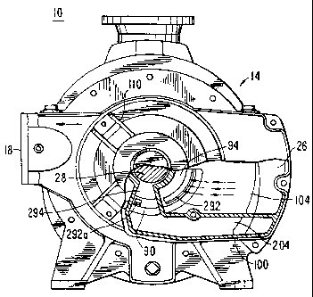
FIG. 1 is an elevational view, partly in
section, of an illustrative embodiment of a two-stage
liquid ring pump constructed in accordance with this
invention.
FIG. 2 is another elevational view, partly in
section, of the pump shown in FIG. 1. FIG. 2 is taken
from the right in FIG. 1, and FIG. 1 is taken from the
left in FIG. 2.
Detailed Description of the Preferred Embodiments
Because the construction of liquid ring
pumps, and even two-stage liquid ring pumps, is so well
known, it will not be necessary to repeat herein a
description of all the structural and operational
details of such pumps. It will suffice to say that the
illustrative pump 10 shown in FIGS. 1 and 2 may be
basically similar to the pump shown and described in

CA 02226799 2006-01-13
- 3 -
the above-mentioned Olsen et al. patent. To facilitate
comparison to the.pump shown in the Olsen et al.
patent, components of the present pump that are similar
to components of the Olsen et al. pump are given the
same reference numbers herein that they have in the
Olsen et al. patent. Components that are new in the
present pump or that are not numbered in the Olsen
et al. patent have three-digit reference numbers herein
that begin with the digit 2.
As viewed in FIG. 2, the first stage 12 of
pump 10 is on the right and the second stage 14 is on
the left. First stage 12 pumps gas from gas inlet 16
to an intermediate pressure and discharges that gas and
some excess pumping liquid from the first stage via
interstage conduit 26. This gas and liquid mixture
flows from right to left along conduit 26 as viewed in
FIG. 2.
As the gas and liquid mixture discharged from
first stage 12 travels along conduit 26, the heavier
liquid portion of this mixture tends to fall toward the
bottom of the conduit due to the effect of gravity.
The portion of conduit 26 adjacent second stage 14 has
a downwardly sloping ramp 226a leading down to a
downwardly depressed bottom portion 226b of the
conduit. The liquid travelling along conduit 26 tends
to separate from the gas and flow down ramp 226a into
depressed lower portion 226b. The gas, on the other
hand, tends to remain above the liquid in the upper
portion of conduit 26 above depressed lower portion
226b.
In second stage head 100 the upper portion of
conduit 26 communicates with second stage gas inlet
passageway 104. Passageway 104 leads to the second

CA 02226799 1998-01-13
- 4 -
stage gas inlet passageway 94 in second stage port
member 90. From passageway 94 gas is pulled into the
working spaces of the second stage via second stage gas
inlet port 292. (Inlet port 292 is not a new feature
in accordance with this invention, but it did not
happen to be depicted in the above-mentioned Olsen
et al. patent. Therefore, it is given a three-digit
reference number in the 200 series.) Because
passageway 104 communicates only with the upper portion
of conduit 26, passageway 104 receives little or no
liquid from conduit 26. Instead, passageway 104
receives primarily gas from conduit 26. This greatly
reduces the amount of liquid entering the second stage
via port 292. Choking of port 292 by liquid from
conduit 26 is thereby substantially reduced or
eliminated.
Instead of liquid from conduit 26 entering
the second stage via port 292, completely separate
liquid passageways are provided in second stage head
member 100 and second stage port member 90 as will now
be described. The downwardly depressed portion 226b of
conduit 26 communicates with a liquid passageway 204 in
second stage head member 100. Passageway 204
communicates with liquid passageway 294 in second stage
port member 90. Passageway 294 leads to a port 292a in
port member 90 for admitting liquid from passageway 294
into the working spaces of second stage 14 downstream
(in the direction of rotation of second stage rotor
blades 82) from second stage gas inlet port 292. Thus
most of the liquid from conduit 26 flows down through
depressed conduit portion 226b, passageways 204 and
294, and enters second stage 14 via a separate liquid
inlet port 292a which is downstream from gas inlet port
292. Because liquid inlet port 292a is separate and

CA 02226799 1998-01-13
- 5 -
downstream from gas inlet port 292, the deleterious
effects in the prior art of admitting both gas and
liquid to the second stage via a single inlet port are
substantially eliminated. Pump performance is thereby
substantially improved as compared to the prior art.
In the illustrative embodiment being
described, the second stage "land" line is vertical and
straight up from the central longitudinal axis of rotor
shaft 28. ("Land" is the location at which the
radially outer tips of rotor blades 82 come closest to
the stationary housing 20 of the pump. The land line
extends from the rotor shaft axis radially out to the
land location.) As viewed in FIG. 1, the rotor rotates
clockwise. Measuring angles from land in the direction
of rotor rotation, a particularly preferred location
for second stage liquid inlet port 292a is at about
200 . Continuing with this example, second stage gas
inlet port may begin to open at about 20 and may close
at about 160 . The second stage gas outlet port (not
shown herein but similar to port 96 in the above-
mentioned Olsen et al. patent) may open at about 258
and may close at about 340 . All of these angles are
only examples and other angles may be used instead if
desired.
As has been said, the following previously
unmentioned components are similar to the
correspondingly numbered components in the above-
identified Olsen et al. patent: outlet opening 18,
first stage stationary housing 22, second stage
stationary housing 24, interstage shroud 36, head
member 60, bearing assembly 70, annular shroud 80, and
bearing assembly 110.
It will be understood that the foregoing is
only illustrative of the principles of this invention,

CA 02226799 1998-01-13
~
- 6 -
and that various modifications can be made by those
skilled in the art without departing from the scope and
spirit of the invention. For example, although the
invention has been illustrated in the context of a pump
which has frusto-conical port members such as port
member 90, the invention is equally applicable to pumps
having port members with other shapes. Examples of
other known shapes are cylindrical port members and
flat port members. Flat port members are shown in such
references is Luhmann U.S. patent 3,108,738, Fitch U.S.
patent 4,132,504, Haavik U.S. patent 4,323,334, and
Auschrat U.S. patent 4,685,865.

Representative Drawing
A single figure which represents the drawing illustrating the invention.
Administrative Status

2024-08-01:As part of the Next Generation Patents (NGP) transition, the Canadian Patents Database (CPD) now contains a more detailed Event History, which replicates the Event Log of our new back-office solution.

Please note that "Inactive:" events refers to events no longer in use in our new back-office solution.

For a clearer understanding of the status of the application/patent presented on this page, the site Disclaimer , as well as the definitions for Patent , Event History , Maintenance Fee  and Payment History  should be consulted.

Event History

Description Date
Inactive: Expired (new Act pat) 2018-01-13
Inactive: Late MF processed 2008-01-18
Letter Sent 2008-01-14
Grant by Issuance 2007-09-25
Inactive: Cover page published 2007-09-24
Letter Sent 2007-07-17
Inactive: Single transfer 2007-07-05
Pre-grant 2007-07-05
Inactive: Final fee received 2007-07-05
Notice of Allowance is Issued 2007-04-26
Letter Sent 2007-04-26
Notice of Allowance is Issued 2007-04-26
Inactive: Approved for allowance (AFA) 2007-04-12
Amendment Received - Voluntary Amendment 2006-08-22
Inactive: S.30(2) Rules - Examiner requisition 2006-03-29
Inactive: IPC from MCD 2006-03-12
Amendment Received - Voluntary Amendment 2006-01-13
Inactive: S.30(2) Rules - Examiner requisition 2005-07-14
Letter Sent 2003-02-12
Amendment Received - Voluntary Amendment 2003-01-10
Letter Sent 2002-11-22
Request for Examination Received 2002-10-23
Request for Examination Requirements Determined Compliant 2002-10-23
All Requirements for Examination Determined Compliant 2002-10-23
Application Published (Open to Public Inspection) 1998-07-30
Inactive: First IPC assigned 1998-04-30
Classification Modified 1998-04-30
Inactive: IPC assigned 1998-04-30
Inactive: Filing certificate - No RFE (English) 1998-04-06
Application Received - Regular National 1998-04-04

Abandonment History

There is no abandonment history.

Maintenance Fee

The last payment was received on 2007-01-03

Note : If the full payment has not been received on or before the date indicated, a further fee may be required which may be one of the following

  • the reinstatement fee;
  • the late payment fee; or
  • additional fee to reverse deemed expiry.

Patent fees are adjusted on the 1st of January every year. The amounts above are the current amounts if received by December 31 of the current year.
Please refer to the CIPO Patent Fees web page to see all current fee amounts.

Owners on Record

Note: Records showing the ownership history in alphabetical order.

Current Owners on Record
GARDNER DENVER NASH LLC
Past Owners on Record
CARL G. DUDECK
RAMESH B. SHENOI
Past Owners that do not appear in the "Owners on Record" listing will appear in other documentation within the application.
Documents

To view selected files, please enter reCAPTCHA code :


To view images, click a link in the Document Description column. To download the documents, select one or more checkboxes in the first column and then click the "Download Selected in PDF format (Zip Archive)" or the "Download Selected as Single PDF" button.

List of published and non-published patent-specific documents on the CPD .

If you have any difficulty accessing content, you can call the Client Service Centre at 1-866-997-1936 or send them an e-mail at CIPO Client Service Centre.


Document
Description 
Date
(yyyy-mm-dd) 
Number of pages   Size of Image (KB) 
Representative drawing 1998-08-03 1 17
Abstract 1998-01-12 1 12
Description 1998-01-12 6 215
Claims 1998-01-12 1 20
Drawings 1998-01-12 2 62
Claims 2006-01-12 1 26
Description 2006-01-12 6 216
Claims 2006-08-21 1 28
Representative drawing 2007-08-27 1 21
Courtesy - Certificate of registration (related document(s)) 1998-04-06 1 118
Filing Certificate (English) 1998-04-05 1 165
Reminder of maintenance fee due 1999-09-13 1 114
Reminder - Request for Examination 2002-09-15 1 116
Acknowledgement of Request for Examination 2002-11-21 1 174
Commissioner's Notice - Application Found Allowable 2007-04-25 1 162
Courtesy - Certificate of registration (related document(s)) 2007-07-16 1 104
Maintenance Fee Notice 2008-02-07 1 174
Late Payment Acknowledgement 2008-02-07 1 167
Fees 2002-12-11 1 31
Fees 2003-12-29 1 30
Fees 1999-11-21 1 28
Fees 2000-12-13 1 29
Fees 2001-12-30 1 34
Fees 2004-12-29 1 30
Correspondence 2007-07-04 2 56