Sélection de la langue

Search

Sommaire du brevet 2226799 

Énoncé de désistement de responsabilité concernant l'information provenant de tiers

Une partie des informations de ce site Web a été fournie par des sources externes. Le gouvernement du Canada n'assume aucune responsabilité concernant la précision, l'actualité ou la fiabilité des informations fournies par les sources externes. Les utilisateurs qui désirent employer cette information devraient consulter directement la source des informations. Le contenu fourni par les sources externes n'est pas assujetti aux exigences sur les langues officielles, la protection des renseignements personnels et l'accessibilité.

Disponibilité de l'Abrégé et des Revendications

L'apparition de différences dans le texte et l'image des Revendications et de l'Abrégé dépend du moment auquel le document est publié. Les textes des Revendications et de l'Abrégé sont affichés :

  • lorsque la demande peut être examinée par le public;
  • lorsque le brevet est émis (délivrance).
(12) Brevet: (11) CA 2226799
(54) Titre français: POMPES A DEUX ETAGES A ANNEAU LIQUIDE
(54) Titre anglais: TWO-STAGE LIQUID RING PUMPS
Statut: Durée expirée - au-delà du délai suivant l'octroi
Données bibliographiques
(51) Classification internationale des brevets (CIB):
  • F04C 19/00 (2006.01)
  • F04C 07/00 (2006.01)
  • F04C 23/00 (2006.01)
(72) Inventeurs :
  • SHENOI, RAMESH B. (Etats-Unis d'Amérique)
  • DUDECK, CARL G. (Etats-Unis d'Amérique)
(73) Titulaires :
  • GARDNER DENVER NASH LLC
(71) Demandeurs :
  • GARDNER DENVER NASH LLC (Etats-Unis d'Amérique)
(74) Agent: GOWLING WLG (CANADA) LLP
(74) Co-agent:
(45) Délivré: 2007-09-25
(22) Date de dépôt: 1998-01-13
(41) Mise à la disponibilité du public: 1998-07-30
Requête d'examen: 2002-10-23
Licence disponible: S.O.
Cédé au domaine public: S.O.
(25) Langue des documents déposés: Anglais

Traité de coopération en matière de brevets (PCT): Non

(30) Données de priorité de la demande:
Numéro de la demande Pays / territoire Date
08/791,508 (Etats-Unis d'Amérique) 1997-01-30

Abrégés

Abrégé français

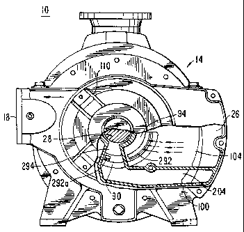
La pompe annulaire à deux étages pour liquide a une structure qui favorise la séparation des gaz et des liquides déchargés du premier étage. Le deuxième étage est pourvu d'orifices d'admission séparés des gaz et des liquides. Cela évite l'étranglement par un liquide de l'orifice d'admission des gaz du deuxième étage, d'où de meilleures performances de la pompe.


Abrégé anglais

A two-stage liquid ring pump has an interstage structure which promotes separation of the gas and liquid discharged from the first stage. The second stage has separate gas and liquid inlets for respectively admitting the separated gas and liquid to the second stage. This avoids any possible choking of the second stage gas inlet by liquid, thereby improving the performance of the pump.

Revendications

Note : Les revendications sont présentées dans la langue officielle dans laquelle elles ont été soumises.


-7-
The Invention Claimed Is
1. A two-stage liquid ring pump comprising:
a first stage outlet for discharging a mixture of gas and liquid from said
first stage,
an interstage structure for separating said gas from said liquid; and
a second stage having separate gas and liquid inlets for respectively
admitting the separated gas and liquid to working spaces between rotor blades
of said
second stage; and
wherein said first and second stage are aligned along at least one continuous
shaft.
2. The liquid ring pump defined in claim 1 wherein said second stage has a
rotor
rotating in a predetermined direction, and wherein said second stage liquid
inlet is downstream
from said second stage gas inlet in the direction of rotation of said rotor.
3. The liquid ring pump defined in claim 2 wherein said second stage liquid
inlet is
approximately 400 beyond the closing of said second stage gas inlet in the
direction of rotor
rotation.

Description

Note : Les descriptions sont présentées dans la langue officielle dans laquelle elles ont été soumises.


CA 02226799 1998-01-13
N/222
TWO-STAGE LIOUID RING PUMPS
Eackqround of the Invention
This invention relates to liquid ring pumps,
and more particularly to liquid ring pumps with two,
serially connected, gas pumping stages.
Two-stage liquid ring pumps are well known,
as is shown, for example, by Olsen et al. U.S. patent
4,521,161. In the usual such pump, a mixture of gas
and liquid is discharged from the first stage and
passed to the inlet of the second stage. The liquid in
this mixture is generally needed in the second stage
(e.g., to make up for liquid discharged with the gas
from the second stage). However, it is believed that
the liquid in the mixture coming from the first stage
may to some extent choke the second stage inlet,
thereby reducing the pressure differential that the
pump can achieve, reducing its volumetric capacity,
and/or increasing its power requirements.
In view of the foregoing, it is an object of
this invention to provide improved two-stage liquid
ring pumps.
It is a more particular object of this
invention to increase the pressure range and volumetric
capacity and to reduce the power requirements of two-
stage liquid ring pumps.

CA 02226799 1998-01-13
- 2 -
Summary of the Invention
These and other objects of the invention are
accomplished in accordance with the principles of the
invention by providing two-stage liquid ring pumps in
which the interstage structure promotes separation of
the gas and liquid discharged from the first stage.
Separate inlets are then provided for respectively
admitting the separated gas and liquid to the second
stage. This avoids any choking of the second stage gas
inlet by liquid from the first stage.
Further features of the invention, its nature
and various advantages will be more apparent from the
accompanying drawings and the following detailed
description of the preferred embodiments.
Brief Description of the Drawings
FIG. 1 is an elevational view, partly in
section, of an illustrative embodiment of a two-stage
liquid ring pump constructed in accordance with this
invention.
FIG. 2 is another elevational view, partly in
section, of the pump shown in FIG. 1. FIG. 2 is taken
from the right in FIG. 1, and FIG. 1 is taken from the
left in FIG. 2.
Detailed Description of the Preferred Embodiments
Because the construction of liquid ring
pumps, and even two-stage liquid ring pumps, is so well
known, it will not be necessary to repeat herein a
description of all the structural and operational
details of such pumps. It will suffice to say that the
illustrative pump 10 shown in FIGS. 1 and 2 may be
basically similar to the pump shown and described in

CA 02226799 2006-01-13
- 3 -
the above-mentioned Olsen et al. patent. To facilitate
comparison to the.pump shown in the Olsen et al.
patent, components of the present pump that are similar
to components of the Olsen et al. pump are given the
same reference numbers herein that they have in the
Olsen et al. patent. Components that are new in the
present pump or that are not numbered in the Olsen
et al. patent have three-digit reference numbers herein
that begin with the digit 2.
As viewed in FIG. 2, the first stage 12 of
pump 10 is on the right and the second stage 14 is on
the left. First stage 12 pumps gas from gas inlet 16
to an intermediate pressure and discharges that gas and
some excess pumping liquid from the first stage via
interstage conduit 26. This gas and liquid mixture
flows from right to left along conduit 26 as viewed in
FIG. 2.
As the gas and liquid mixture discharged from
first stage 12 travels along conduit 26, the heavier
liquid portion of this mixture tends to fall toward the
bottom of the conduit due to the effect of gravity.
The portion of conduit 26 adjacent second stage 14 has
a downwardly sloping ramp 226a leading down to a
downwardly depressed bottom portion 226b of the
conduit. The liquid travelling along conduit 26 tends
to separate from the gas and flow down ramp 226a into
depressed lower portion 226b. The gas, on the other
hand, tends to remain above the liquid in the upper
portion of conduit 26 above depressed lower portion
226b.
In second stage head 100 the upper portion of
conduit 26 communicates with second stage gas inlet
passageway 104. Passageway 104 leads to the second

CA 02226799 1998-01-13
- 4 -
stage gas inlet passageway 94 in second stage port
member 90. From passageway 94 gas is pulled into the
working spaces of the second stage via second stage gas
inlet port 292. (Inlet port 292 is not a new feature
in accordance with this invention, but it did not
happen to be depicted in the above-mentioned Olsen
et al. patent. Therefore, it is given a three-digit
reference number in the 200 series.) Because
passageway 104 communicates only with the upper portion
of conduit 26, passageway 104 receives little or no
liquid from conduit 26. Instead, passageway 104
receives primarily gas from conduit 26. This greatly
reduces the amount of liquid entering the second stage
via port 292. Choking of port 292 by liquid from
conduit 26 is thereby substantially reduced or
eliminated.
Instead of liquid from conduit 26 entering
the second stage via port 292, completely separate
liquid passageways are provided in second stage head
member 100 and second stage port member 90 as will now
be described. The downwardly depressed portion 226b of
conduit 26 communicates with a liquid passageway 204 in
second stage head member 100. Passageway 204
communicates with liquid passageway 294 in second stage
port member 90. Passageway 294 leads to a port 292a in
port member 90 for admitting liquid from passageway 294
into the working spaces of second stage 14 downstream
(in the direction of rotation of second stage rotor
blades 82) from second stage gas inlet port 292. Thus
most of the liquid from conduit 26 flows down through
depressed conduit portion 226b, passageways 204 and
294, and enters second stage 14 via a separate liquid
inlet port 292a which is downstream from gas inlet port
292. Because liquid inlet port 292a is separate and

CA 02226799 1998-01-13
- 5 -
downstream from gas inlet port 292, the deleterious
effects in the prior art of admitting both gas and
liquid to the second stage via a single inlet port are
substantially eliminated. Pump performance is thereby
substantially improved as compared to the prior art.
In the illustrative embodiment being
described, the second stage "land" line is vertical and
straight up from the central longitudinal axis of rotor
shaft 28. ("Land" is the location at which the
radially outer tips of rotor blades 82 come closest to
the stationary housing 20 of the pump. The land line
extends from the rotor shaft axis radially out to the
land location.) As viewed in FIG. 1, the rotor rotates
clockwise. Measuring angles from land in the direction
of rotor rotation, a particularly preferred location
for second stage liquid inlet port 292a is at about
200 . Continuing with this example, second stage gas
inlet port may begin to open at about 20 and may close
at about 160 . The second stage gas outlet port (not
shown herein but similar to port 96 in the above-
mentioned Olsen et al. patent) may open at about 258
and may close at about 340 . All of these angles are
only examples and other angles may be used instead if
desired.
As has been said, the following previously
unmentioned components are similar to the
correspondingly numbered components in the above-
identified Olsen et al. patent: outlet opening 18,
first stage stationary housing 22, second stage
stationary housing 24, interstage shroud 36, head
member 60, bearing assembly 70, annular shroud 80, and
bearing assembly 110.
It will be understood that the foregoing is
only illustrative of the principles of this invention,

CA 02226799 1998-01-13
~
- 6 -
and that various modifications can be made by those
skilled in the art without departing from the scope and
spirit of the invention. For example, although the
invention has been illustrated in the context of a pump
which has frusto-conical port members such as port
member 90, the invention is equally applicable to pumps
having port members with other shapes. Examples of
other known shapes are cylindrical port members and
flat port members. Flat port members are shown in such
references is Luhmann U.S. patent 3,108,738, Fitch U.S.
patent 4,132,504, Haavik U.S. patent 4,323,334, and
Auschrat U.S. patent 4,685,865.

Dessin représentatif
Une figure unique qui représente un dessin illustrant l'invention.
États administratifs

2024-08-01 : Dans le cadre de la transition vers les Brevets de nouvelle génération (BNG), la base de données sur les brevets canadiens (BDBC) contient désormais un Historique d'événement plus détaillé, qui reproduit le Journal des événements de notre nouvelle solution interne.

Veuillez noter que les événements débutant par « Inactive : » se réfèrent à des événements qui ne sont plus utilisés dans notre nouvelle solution interne.

Pour une meilleure compréhension de l'état de la demande ou brevet qui figure sur cette page, la rubrique Mise en garde , et les descriptions de Brevet , Historique d'événement , Taxes périodiques et Historique des paiements devraient être consultées.

Historique d'événement

Description Date
Inactive : Périmé (brevet - nouvelle loi) 2018-01-13
Inactive : TME en retard traitée 2008-01-18
Lettre envoyée 2008-01-14
Accordé par délivrance 2007-09-25
Inactive : Page couverture publiée 2007-09-24
Lettre envoyée 2007-07-17
Inactive : Transfert individuel 2007-07-05
Préoctroi 2007-07-05
Inactive : Taxe finale reçue 2007-07-05
Un avis d'acceptation est envoyé 2007-04-26
Lettre envoyée 2007-04-26
Un avis d'acceptation est envoyé 2007-04-26
Inactive : Approuvée aux fins d'acceptation (AFA) 2007-04-12
Modification reçue - modification volontaire 2006-08-22
Inactive : Dem. de l'examinateur par.30(2) Règles 2006-03-29
Inactive : CIB de MCD 2006-03-12
Modification reçue - modification volontaire 2006-01-13
Inactive : Dem. de l'examinateur par.30(2) Règles 2005-07-14
Lettre envoyée 2003-02-12
Modification reçue - modification volontaire 2003-01-10
Lettre envoyée 2002-11-22
Requête d'examen reçue 2002-10-23
Exigences pour une requête d'examen - jugée conforme 2002-10-23
Toutes les exigences pour l'examen - jugée conforme 2002-10-23
Demande publiée (accessible au public) 1998-07-30
Inactive : CIB en 1re position 1998-04-30
Symbole de classement modifié 1998-04-30
Inactive : CIB attribuée 1998-04-30
Inactive : Certificat de dépôt - Sans RE (Anglais) 1998-04-06
Demande reçue - nationale ordinaire 1998-04-04

Historique d'abandonnement

Il n'y a pas d'historique d'abandonnement

Taxes périodiques

Le dernier paiement a été reçu le 2007-01-03

Avis : Si le paiement en totalité n'a pas été reçu au plus tard à la date indiquée, une taxe supplémentaire peut être imposée, soit une des taxes suivantes :

  • taxe de rétablissement ;
  • taxe pour paiement en souffrance ; ou
  • taxe additionnelle pour le renversement d'une péremption réputée.

Les taxes sur les brevets sont ajustées au 1er janvier de chaque année. Les montants ci-dessus sont les montants actuels s'ils sont reçus au plus tard le 31 décembre de l'année en cours.
Veuillez vous référer à la page web des taxes sur les brevets de l'OPIC pour voir tous les montants actuels des taxes.

Titulaires au dossier

Les titulaires actuels et antérieures au dossier sont affichés en ordre alphabétique.

Titulaires actuels au dossier
GARDNER DENVER NASH LLC
Titulaires antérieures au dossier
CARL G. DUDECK
RAMESH B. SHENOI
Les propriétaires antérieurs qui ne figurent pas dans la liste des « Propriétaires au dossier » apparaîtront dans d'autres documents au dossier.
Documents

Pour visionner les fichiers sélectionnés, entrer le code reCAPTCHA :


Pour visualiser une image, cliquer sur un lien dans la colonne description du document. Pour télécharger l'image (les images), cliquer l'une ou plusieurs cases à cocher dans la première colonne et ensuite cliquer sur le bouton "Télécharger sélection en format PDF (archive Zip)" ou le bouton "Télécharger sélection (en un fichier PDF fusionné)".

Liste des documents de brevet publiés et non publiés sur la BDBC .

Si vous avez des difficultés à accéder au contenu, veuillez communiquer avec le Centre de services à la clientèle au 1-866-997-1936, ou envoyer un courriel au Centre de service à la clientèle de l'OPIC.


Description du
Document 
Date
(aaaa-mm-jj) 
Nombre de pages   Taille de l'image (Ko) 
Dessin représentatif 1998-08-03 1 17
Abrégé 1998-01-12 1 12
Description 1998-01-12 6 215
Revendications 1998-01-12 1 20
Dessins 1998-01-12 2 62
Revendications 2006-01-12 1 26
Description 2006-01-12 6 216
Revendications 2006-08-21 1 28
Dessin représentatif 2007-08-27 1 21
Courtoisie - Certificat d'enregistrement (document(s) connexe(s)) 1998-04-06 1 118
Certificat de dépôt (anglais) 1998-04-05 1 165
Rappel de taxe de maintien due 1999-09-13 1 114
Rappel - requête d'examen 2002-09-15 1 116
Accusé de réception de la requête d'examen 2002-11-21 1 174
Avis du commissaire - Demande jugée acceptable 2007-04-25 1 162
Courtoisie - Certificat d'enregistrement (document(s) connexe(s)) 2007-07-16 1 104
Avis concernant la taxe de maintien 2008-02-07 1 174
Quittance d'un paiement en retard 2008-02-07 1 167
Taxes 2002-12-11 1 31
Taxes 2003-12-29 1 30
Taxes 1999-11-21 1 28
Taxes 2000-12-13 1 29
Taxes 2001-12-30 1 34
Taxes 2004-12-29 1 30
Correspondance 2007-07-04 2 56