Note: Descriptions are shown in the official language in which they were submitted.
CA 02227057 1998-O1-15
WO 97!46788 PCT/CA97/00370
DOWNHOLE ANCHOR
° Field of the Invention
The present invention relates to an anchor which prevents rotation of a
member, such as a tubing string, within a well.
Background of the Invention
The drive rods of progressive cavity pumps, also known as screw-type
pumps, tend to impart torque to the pump during operation. This torque causes
both
the pump and the tubing string to rotate in a right hand direction, when
viewed from the
top. Such rotation is detrimental to the pumping operation.
An anchor is known for use with a progressive cavity pump and is
described in Canadian Patent no. 1,274,470 issued September 25, 1990 to Weber.
This anchor has a drag assembly and a slip assembly disposed about a central
tubular
member though which the well fluids can pass. The drag assembly carries a drag
means, such as spring-biased drag blocks or belly-type springs, and is free to
rotate
relative to the tubular member. The slip assembly is formed about the tubular
member
in engagement with the drag assembly. The slip assembly houses slip members
having casing engaging surtaces, which are driven between a retracted position
and
an extended engaging position by action of the drag and slip assemblies
rotating about
the central tubular member and slip members moving over the surface of the
tubular
member where if is formed as a mandrel.
Another anchor is described in U.S. Patent 5,275,239 issued January 4,
1994 to Obrejanu. This anchor has a slip assembly housing slip members which
are
formed to engage the casing when the anchor is rotated in a predefined
direction.
- ~ - These anchors are quite complex and require the use of springs to drive
the slip members. The springs are subject to failure and displacement which
limits the
useful life of each of the anchors. Additionally, the slip members of these
anchors
always extend out past the surtace curvature of the slip housing and are
subject to
CA 02227057 1998-O1-15
WO 97/46788 PCT/CA97/00370
-2-
wear when they come into contact with the casing wall during anchor placement
and
retrieval. It is difficult to remove the slips from the housings in these
anchors which a
makes them very difFicult to refurbish andlor repair.
Summary of the Invention
An anchor for use with a progressive cavity pump has been invented
which eliminates spring-biased slip members. In one embodiment, the slip
members
of the anchor can be driven into a retracted position so that they do not come
into
contact with the casing during anchor placement or retrieval.
In accordance with a broad aspect of the present invention, there is
provided a downhole tool for preventing rotational movement of a member within
a well
comprising an elongate tubular member having a central axis; a slip housing
disposed
about the tubular member and carrying at feast two slip members, the slip
members
each being rotatable about an axis substantially parallel to the central axis
of the
tubular member between a retracted position, against the housing, and an
extended
position; a drag housing carrying drag means and being mounted on and
rotatable
about the tubular member; and an actuator to drive the rotation of the slip
members in
response to the rotation of the tubular member within the drag housing.
Description of the invention
The invention provides an anchor for use in preventing the rotation of a
downhole member such as a pump or a tubing string, within a well. The anchor
is
positionable within the well about the member to be anchored. It is
particularly useful
to act against a stationary well structure, such as the well casing, to
prevent vibration
of-a 'progressive cavity pump which produces torque in a right hand direction
during
use.
CA 02227057 1998-O1-15
WO 97/46788 PCT/CA97/00370
__ _ _.3_
The anchor preferably has a central tube segment which is attachable to a pump
, or which can be inserted in-line into a production tubing string. The tube
segment nas
a hollow bore along its central axis for the passage of production fluids,
such as oil and
' water, and ends suitably adapted, such as by threading, for connection to
other tube
members or pumps. The outer surface of the tube segment supports a drag
assembly
and a slip assembly. The drag assembly includes a drag housing which carries a
suitable number of drag means. As an example, the drag means can introduce
drag
between the drag means and the well casing through either frictional or
viscous action.
Frictional drag action can be accomplished by outwardly spring-biased drag
blocks or belly-type springs provided in the drag assembly. For frictional
action, at
least two drag means are preferred so that the tube segment is approximately
centred
in the casing and is not squeezed against one arc of the casing. The drag
assembly
preferably has three drag means equidistantly spaced about the perimeter, the
drag
means comprising, for example, three belly springs spaced equally on the drag
assembly. The drag means act to engage the well casing frictionally when the
anchor
is placed in the well. The frictional engagement between the drag means and
the well
casing is selected so that it can be overcome by application of a reasonable
amount
of force, but so that it will maintain the positioning of the drag assembly
during
application of the degree of torque which is applied during operation of a
progressive
cavity pump.
For viscous drag action, the drag assembly has at least two, and
preferably three drag means, each drag means comprising vanes dimensioned to
be
slidably received in the well casing with each vane defining a vane surface in
close
proximity to the well casing. In combination with fluids found in the well,
such as water
or hydrocarbons which are to be pumped from the well, the vanes, well casing
and
viscous fluid..interact to introduce viscous drag upon rotation of the drag
assembly in
relation to the well casing during set-up of the well anchor of the present
invention.
The vanes are preferably generally radially displaced about the circumference
of the
CA 02227057 1998-O1-15
WO 9?/46788 PCT/CA97/00370
.. . i4=
drag means to ensure that sufficient annular space remains to allow fluid flow
for
pumping.
The drag assembly is preferably mounted on the tubular member in such
a way that it can rotate about the central axis of the tubular member. In one
embodiment, the drag housing engages an annular flange formed about the
tubular
member. In another embodiment, a plurality of slots is formed about the
circumference
of the drag housing though which fasteners, such as bolts, are inserted to
engage the
tube. The fasteners can slide within the slots to permit a degree of rotation
of the
assembly about the tube.
1 a The slip assembly includes a housing which can be separate from the
tube segment or formed integral therewith. The housing carries at feast two
slip
members. In a preferred embodiment, three slip members are spaced equally
about
the circumference of the housing. The slip members are pivotally mounted to
the
housing in any suitable way, such that they are free to rotate about an axis
which is
substantially parallel to the central axis of the tube. The slip members
rotate between
a retracted position, in which they are folded against the surface of the
housing, and
an extended position, in which they extend out from the housing and tube. in a
preferred embodiment, all of the slip members rotate from the retracted
position to the
extended position in the same direction. In this embodiment, the anchor is
useful to
anchor a well member against rotation in a direction opposite to the direction
in which
the slip members rotate from the retracted position to the extended position.
The slip housing preferably has formed thereon a contact area for each
slip member on which the slip member seats when in the anchoring position. In
one
embodiment, the slip members are disposed in recesses formed in the slip
housing
such-that when they are in the retracted position they remain below the plane
of the
surface of the housing. In this embodiment, the contact areas are formed in
the
recesses and the outer edges of the slip members extend beyond the surface
curvature
of the housing when in the extended position. In a preferred embodiment, the
contact
CA 02227057 1998-O1-15
WO 97/46788 PCT/CA97/00370
.. . _5_
area is formed to substantially conform to the shape of the base of the slip
member to
provide a broad surface area contact therebetween.
' The outer edges of the slip members are preferably formed to enhance
their engagement against surFaces such as casing steel. For example, the edge
of the
slip members can be formed with sharpened serrations.
An actuator is disposed between the drag assembly and the slip
assembly. The actuator drives the rotation of the slip members about their
axis of
rotation in response to rotation of the drag means relative to the tube
segment. The
actuator can be any suitable arrangement for communicating the relative
rotation of the
drag means to the slip members. In one embodiment, one actuator is provided
for each
slip member. A suitable actuator can be, for example, a pair of protrusions
which
extend out from the edge of the drag assembly to contact opposing surfaces of
a slip
member. Rotation of the drag assembly moves the protrusions which push the
slip
member. In another embodiment, the actuator is a pin extending from the slip
member
_ which is engaged and driven by the drag assembly. The pin can be, for
example, a
gear-like arrangement which meshes with and is driven by a toothed portion on
the
drag housing. In a preferred embodiment, the pin extends from an end of the
slip
member and is offset from the axis of rotation of the slip member and extends
into a
groove formed in the end face of the drag housing. The groove extends on the
end
face from a first position, adjacent the outer diameter, to a second position,
circumferentially spaced from the first position and adjacent the inner
diameter of the
end face.
in use, the anchor is placed to prevent rotation of a member, such as a
section of tubing, against rotation in a preselected direction. The anchor is
placed in
the-welt such that the tube segment is in communication with the member to be
anchored. For example, the tube segment can be inserted into the tubing
string. The
anchor is further positioned such that the drag assembly is dragging against
the well
casing. For frictional drag means drag assemblies, the drag means are in
contact with
CA 02227057 1998-O1-15
WO 97!46788 PCT/CA97/00370
-6 -
and frictionally engage the casing by biased contact with the well casing. For
viscous
drag means drag assemblies, the drag means are lowered into the well casing
until the
drag assembly becomes surrounded by fluid such that proximate positioning of
the
outer surface of the drag means to the well casing causes dragging engagement
of the '
drag means to the well casing through the intermediary of the viscous fluid
present in
the well. The slip members are in position to rotate from the retracted
position to the
extended position in a direction which is opposite to the direction of
rotation of the
tubing string to be anchored. When torque is communicated to the tube segment
of the
anchor, the tube will rotate within the drag assembly, which is prevented from
rotating
by means of the dragging engagement of the drag means with the casing. This
rotation
of the tube within the drag assembly, causes the actuator to drive the slip
members
from the retracted position, which they are in during anchor placement, to the
extended
position whereby the slip members engage against the casing wall. Upon
engaging the
casing wall, the slip members wedge between the contact area of the tube
segment and
the casing wall to anchor the tube segment against further rotation. This then
prevents
further rotation of the attached tubing string.
Brief Description of the Drawings
A further, detailed, description of the invention, briefly described above,
will follow by reference to the following drawings of specific embodiments of
the
invention. These drawings depict only typical embodiments of the invention and
are
therefore not to be considered limiting of its scope. In the drawings:
Figure 1 is a front elevation of an anchor of the present invention;
Figure 2 is a view along line 2-2 of Figure 1 with the anchor shown in
relation to a segment of well casing;
-- - --Figure 3 is a view along line 3-3 of Figure 1 with only one slip member
in ,
position;
Figures 4A, 4B and 4C are front elevation, end elevation and top plan
views, respectively, of a slip member;
CA 02227057 1998-O1-15
WO 97/46788 PCTlCA97/00370
-7-
Figures 5A and 5B are schematic views of slip members wedging between
the tubing segment and the casing wall;
Figure 6 is an end elevation of the drag housing of Figure 1; and
' Figure 7 is a sectional view along another embodiment of an anchor of
the present invention.
Figure 8 is an exploded plan view of an embodiment of an anchor of the
present invention with a viscous drag housing.
Figure 9 is a down hole end view of the viscous drag housing in a well
casing shown in cross-section.
Figure 10, 10a and 10b are front elevation and opposing end views of an
alternative embodiment of a slip member in accordance with the present
invention.
Description of the Preferred Embodiments
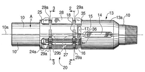
Referring to Figures 1, 2 and 3, the anchor has a piece of tubing 10 with
a bore 11 through it for oil to pass upwardly. The tubing 10 is of small
enough outer
diameter to provide an annulus between the tubing and the casing 12 of the
welt.
On the exterior of the tubing 10 is mounted a drag assembly indicated
generally as 13. The drag assembly includes a cylindrical housing 13a disposed
about
tubing 10. Belly springs 14 are mounted in recesses 15 formed in the surface
of
housing 13a. in an alternate embodiment, drag blocks and drag block springs
are
used, as is known. The function of either the drag block or the bel ly spring
is to provide
the drag housing with some resistance to rotational movement, although the
resistance
is slight and can relatively easily be overcome. Thus, the drag block or belly
spring
biases against the casing when the tubing is raised or lowered within the
casing, but
does not bias sufficiently strongly to prevent such raising or lowering. It
also resists
rotation of the tubing, but not enough to prevent such rotation.
A portion 16 of housing 13a extends out and has formed therein a slot 17.
A bolt 18 is secured to tubing 10 through slot 17. Drag assembly 13 is
attached to
CA 02227057 1998-O1-15
WO 97/46788 PCT/CA97100370
_g_
tubing 10 by means of the head of bolt 18 engaging against the edges of slot
17.
However, drag assembly 13 can rotate about tubing 10. ,
Adjacent to drag assembly 13, in an upward direction as the tubing would
be oriented in a well, is the slip assembly 20. Slip assembly 20 includes
three elongate
recesses 23, 24 and 25 formed in the outer surface of tubing 10. Each recess
is
generally U-shaped with one sloped side, as shown at 23a, 24a and 25a, and one
generally upstanding side 23b, 24b, 25b. The slopes are formed on the same
sides of
the recesses.
Retained in recesses 23, 24 and 25 are slip members 26, 27, 28. These
are mounted so as to be pivotal about their long axes, which are substantially
parallel
to the long axis 10a of tubing 10. The slip members can rotate through an arc
to abut
against sloped side 23a, 24a, 25a and upstanding side 23b, 24b, 25b. Slip
members
26, 27, 28 are retained in place by keepers 29a, 29b which extend out into the
openings of the recesses. Keepers 29a extend from sloped sides 23a, 24a, 25a
while
keepers 29b are secured adjacent sides 23b, 24b, 25b. In the preferred
embodiment,
keepers 29a extend a selected distance over the surface of recesses to prevent
slip
members 26, 27, 28 from being forced out of the recesses by over centring.
The slip members 26, 27, 28 each have a larger cylindrical base portion
30 and an outer edge portion 31 (see Figures 4A to 4C). The outer edge portion
has
serrations 32 which engage with the casing wall 12. Portion 31 and serrations
32 are
absent at two positions 33 along the members to allow for placement of keepers
29a,
29b. The slip members are circular in cross section at portions 33 to allow
for rotation
beneath keepers 29a, 29b. Serrations are formed with a cutting edge which will
bite
into casing steel. With reference also to Figures 5A and 5B, prefereably the
tips of
serrations 32 are stepped such that at least some of the serrations will
engage with the ,
casing wall regardless of the degree of rotation of the slip members. This
permits an
anchor to be used in a range of well casing diameters. For example, Figure 5A
shows
an anchor having a slip member 26a in a casing 12a having a diameter d'. Slip
CA 02227057 1998-O1-15
WO 97/46788 PCT/CA97/00370
.. _ ~9_
member 26a is rotated at an angle x' from perpendicular. Figure 5B shows the
anchor
in a casing 12b having a larger diameter d" than that shown in Figure 5A. Slip
member
26a is rotated at a angle x", which is less than that of x'. In each case two
serrations
' are in contact with the casing.
The slip members contact the recesses at contact area 34. Recesses 23,
24, 25, substantially conform to the shape of the cylindrical base portion 30
to enhance
transmission of forces to the tubing and to provide support for the slip
members.
Slip members 26, 27, 28 each have a cylindrical pin 35 extending from
their lower ends. fn this embodiment, pin 35 is offset from the axes of
rotation of
members 26, 27, 28. Referring to Figures 1, 3 and 6, each pin 35 registers
with a
groove 36 formed in the end face of drag housing 13a. Grooves 36 spiral
inwardly from
the outer edges of the end face toward the centre. The pins ride in the
grooves and
move in response to rotational movement of the drag housing relative to the
tubing 10.
As pins 35 ride along the groove this drives the rotation of the slip members
within the
recesses. While the grooves are shown arched, it is to be understood that
grooves can
be linear.
In use, the anchor is inserted into the well to prevent rotation of a
member, such as a tubing string or pump within the well. The anchor as shown
in the
drawings is attached such that end 10' is uppermost. End 10' can be, for
example
threadably engaged to a pump, not shown, and the opposite end is attached to
the
upper end of a tubing string, also not shown.
When the anchor is raised and lowered in the well, the slip members are
in tF~e retracted position in which slip members 26, 27, 28 rest against the
sloped sides
23a, 24a, 25a of the recesses and pins 35 are at the inner end of grooves 36.
In this
position, the serrations do not touch the casing. However, when the anchor is
in place,
and the screw pump is started, rotational torque is imparted to tubing 10
which causes
CA 02227057 1998-O1-15
WO 97/46788 PCT/CA97/00370
. __10
it to turn within the casing. The anchor shown in the Figures is intended to
be used
against torque which causes the tubing to turn in the direction as shown by
arrows A.
The belly springs 14, or the equivalent drag blocks, which are always in
contact with
the casing, provide a certain measure of drag against such rotation, although
their force
is not strong enough to prevent it. As the drag assembly is initially
prevented from
turning with the tubing 10, the tubing rotates within the drag assembly 13. As
tubing
rotates within drag housing 13a, pins 35 ride out along grooves 36 and thereby
cause slip members 23, 24, 25 to rotate in a direction as shown by arrow B,
which is
opposite to direction A, to an extended position until portion 31 contacts the
casing and
10 serrations 32 bite into the casing. The slip members wedge between the
tubing and the
casing and this effectively prevents further turning of the tubing 10.
When it is desired to permit movement of the tubing 10 relative to the
casing, the tubing is rotated in the opposite direction to that of arrows A.
This causes
outer edge portions 31 to again lie against sloped sides 23a, 24a, 25a so that
the slip
members no longer oppose rotation.
Referring to Figure 7, another embodiment of the anchor is shown which
includes tubing 210, a drag assembly 213 and a slip assembly 220. The drag
assembly
includes a cylindrical housing 213a in which drag blocks 250 are mounted. Drag
blocks
250 are retained in recesses 215 formed in the housing 213a. Drag block
springs 252
urge drag blocks 250 outwardly into contact with lower retaining flange 253
and upper
retaining flange 254. Upper retaining flange 254 is formed integral with an
actuating
ring 256. Ring 256 is engaged to drag housing 213a and fits loosely over
tubing 210,
so it can rotate with drag housing 213a about tubing 210. A retaining ring 257
maintains ring 256 in position along the length of tubing 210.
-- - - -. Slip assembly includes a housing 260 fixedly mounted on tubing 210.
Slip
members 226 (only one can be seen) are mounted in housing 260 and rotate about
their axles 259 between a retracted position and an extended position, as
discussed
hereinbefore. A retaining wall 261, formed integral with housing 260 retains
slip
CA 02227057 1998-O1-15
WO 97/46788 PCT/CA97/00370
_ -11 -
members 226 at their upper end and actuating ring 256 retains them at their
lower end.
Ring 256 has protrusions 262 which extend out to contact opposing surfaces of
each
slip member 226. Rotation of ring 256 moves the protrusions which push the
slip
members between a retracted position and an extended position, as shown.
Referring to Figure 8 an alternate embodiment of the anchor of the
present invention is shown. The anchor is provided with a plurality of slip
members 26
retained within the anchor assembly by means of keepers 29a and 29b. The slip
members 26 are rotatably mounted within the slip assembly 20 to permit the
slip
member to rotate between a retracted position and an extended position. The
slip
member 26 of Figure 8 is shown in its extended position. When in a retracted
position
the slip member 26 will rotate to lie in contact with the sloped side 23a
recess to
decrease the diameter of the slip assembly 20 permitting it to be slid into or
out of a
well casing or rotate in a limited manner within the casing 12. Shown removed
from the
slip assembly is the drag assembly 13 which is provided with a plurality of
vanes 38
that have an outer vane surface 40 dimensioned to be slidably received within
a well
casing 12 but which react with a viscous fluid 42 (of Figure 9) to introduce a
drag force
tending to oppose rotation between the drag assembly 13 and a well casing 12.
As the
drag assembly 13 is rotatably mounted on slip assembly 20, the drag forces
tend to
cause the drag assembly 13 to rotate with respect to the slip assembly 20. The
amount
of rotation permitted between the drag assembly 13 and the slip assembly 20 is
limited
by slots 17 provided in the end portion of the drag assembly 13 which are
dimensioned
to slidably receive bolt 18 therein. Bolt 18 is threaded into a threaded
receiving bore
19 provided on the slip assembly 20.
Rotation of the drag assembly 13 with respect to the slip assembly causes
the slip members 26 to move into an extended position through operation of pin
35
which is constrained to move along the path of groove 36 of the drag assembly.
When the anchor assembly moves or rotates in the direction depicted by
arrow A of Figure 8, as for example due to coupled reaction forces on the
anchor
f
CA 02227057 1998-O1-15
WO 97146788 PCT/CA97/00370
-12-
caused by operation of a pump, drag forces between drag assembly 13 and the
interior
surface of well casing 12 will cause drag assembly 13 to rotate with respect
to slip
assembly 20 whereby pin 35 will move along groove 36 to extend slip members 26
outwardly to frictionally engage the interior surface of the well casing 72.
As a result, '
the anchor of the present invention will stop further rotation between the
slip assembly
20 and the wel! casing 12. Conversely, when the torque is applied to tubing 10
to cause
the slip assembly 20 to rotate in the direction opposite that depicted by
arrow A the
drag forces acting on the drag assembly 13 will cause the slip members 26 to
retract
inwardly to coextend within recess 23 thereby releasing the anchor of the
present
invention from engagement With the casing 12.
Referring to Figures 10 and 10b, there is shown an alternate embodiment
of a slip member 26 of the present invention. In accordance with this
embodiment of
the invention, the slip member 26 is provided with a single serration absent
location 33.
The outer extent of outer edge portion 31 of the slip member is provided with
a plurality
of serrations 32 for positive frictional engagement of the interior surface of
a well casing
12.
!t will be apparent that many changes may be made to the illustrative
embodiments, while failing within the scope of the invention and it is
intended that all
such changes be covered by the claims appended hereto.