Note: Descriptions are shown in the official language in which they were submitted.
CA 02227428 1997-10-20
W O96/33013 PCTIUS96105303
EN~lANCED ADSORBENT AND ROOM TEMPERATURE
CATALYST PARTICLE AND
METHOD OF MAKING AND USING l~Rli ~OR
S BACKGROUND OF TElE INVENTION
I~IELD OF T~E INVENTION
This invention relates generally to adsorbent particles that have i~--p~ved
10 adsorbent pl ope- ~ies and/or i,..~. o~ed or newly existing catalytic p. upt;- ~ies, incl.lflinp
room temperature catalyltic capability.
BACKGROUND ART
Oxides of metals and certain non-metals are known to be useful for
removing conctitu~ntc from a gas or liquid stream by adsorbent . .~ c "c For
PY~mple~ the use of activated ~ min~ is con~id~red to be an econo. :c~l method ~or
treating water for the removal of a variety of polll~t~nt~, gasses, and some liquids. Its
highly porous structure allows for p,~re,e"lial adso,~Li~e capacity for moisture and
20 co..ln ;~ cont~ined in gasses and some liquids. It is useful as a de~ cc~l for gasses
and vapors in the petroleum industry, and has also been used as a catalyst or catalyst-
carrier in air and in water purific~tiQn Removal of co ~ such as phosphates by
activated ~ min~ are known in the art See, for ~y~mple~ Yee, W, "Selective Removal
of Mixed Phosphates by Activated ~ min~," J.Amer. Waterworks Assoc., Vol 58, pp
25 239-247 (19~6).
U S Patent No 5,242,879 to Abe et aL discloses that activated carbon
materials, which have been subjecl:ed to carbonization and activation tre~tm~nte~ and
30 then further subjected to an acid Lle~ -l and a heat l,e~ in an atmosphere
comprising an inert gas or a reducing gas, have a high catalytic activity and are suitable
as catalysts for the decomposition of hydrogen peroxide, hyd~ es or other water
pollutants such as organic acids, quaternary ~mmonium-salts, and sulfur-co.~l~il i g
SU~llll~lk ~H~tl (R~JLE2G~
CA 02227428 1997-10-20
W O96/33013 PCTrUS96/05303
compounds. Acid is used to remove impurities and not to ~nh~nce the adso
r~LUI~s.
Ion illlplallLalion has been used in integrated circuit fabrication. U.S.
5 Patent No. 4,843,034 to Herndon et al. tliecloses methods and systems for fabricating
interlayer conductive paths in integrated circuits by implanting ions into selected regions
of normally insulative layers to change the composition and/or structure of the ine~ tit~n
in the selected regions. It is stated that a wide range of insulative materials can be
rendered selectively conductive, inclllding polymeric inelll~tors and inorganic inclll~tors,
10 such as metal or semi-con~1~lctQr oxides, nitrides or carbides. Tne~ tors which can be
processed according to this patent include silicone dioxide, silicon nitride, silicon
carbide, ~Illmimlm oxides, and others. It is ~lieclosed that ;",plA..~ed ions can include
ions of silicon, gel",~"i~lm~ carbon, boron, arsenic, phosphorous, tit~nillm, molybdenum,
~Illmimlm, and gold. Typically, the imrl~nt~tion energy varies from about 10 to about
15 500 KeV. It is disclosed that the ion impl~nt~tion step changes the composition and
structure of the insulative layer and is believed also to have the effect of diepl~ing
oxygen, nitrogen, or carbon so as to promote the migration and alloying of metal from
the conductive layer(s) into the imrl~nted region during the ~illL~ g step. The
i llpl~ll~Lion also is believed to have the physical effect of di~lupL;Ilg the crystal lattice,
20 which may also f~rilit~te the fusion of the metal. This results in a composite material in
the impl~nt~tion region çeeenti~lly col1~;e~ g ofthe disruptive inelll~tor and ;",p~ ed
ions. In the working examples, ions of silicon were imrl~nted into the particular region
of the silicon dioxide layer using a direct ;" ,pl~ ;on m~chine
U.S. Patent No. 5,218,179 to Matossian et aL diecloses a plasma source
arrangement for providing ions for ;..,?l~"l~;on into an object. A large scale object
which is to be imrl~nted with ions is enclosed in a conla;ller. The plasma is genel~d in
a chamber which is se~ le from, and opens into the co"~ r for a plasma source ion
imrl~nt~tion working volume. The plasma defuses from the ch~lll)el into the container
30 to surround the object with substantially improved density colllp~ued to conventional
tSb~tl (RULE26)
CA 02227428 1997-10-20
W O96/33013 PCTrUS96/05303
-3-
practice. High voltage negative pulses are applied to the object, causing the ions ~o be
accelerated from the plasma toward and be ;,.,p~ ed into the object.
Thus, there has been a need in the art for adsorbents that have improved
S ability to adsorb particular m~teri~l~ especially co~ "l~; from a gas or liquid
stream, to thereby purify the stream. Also, there has been a need in the art for catalysts
that have the ability or that have an improved ability to catalyze the reaction of
Co.~ s into non-co~ .l by-products.
Additionally, there has been a need in the art for adequately
~gglolll~ ing adsorbent particles together to form a composite particle for pe,ro".~i"g
eiml~lt~n~o~l~ multiple applicati.ons and purifications. In the prior art, particles have been
ground up and extruded together to hold them in an agglo~ ed or combined state.
This has the drawback of requiring an e~l,ensi~e extrusion step, wherein particular
15 eqllipm~nt and processing time is needed to extrude the particles together.
None ofthe above-cited doclll~l~llle discloses co--lpclu--ds, compositions
or processes such as those described and claimed herein.
SUl~A[MA~RY OF TEE INVENTION
In accordance with the purpose(s) of this invention, as embodied and
broadly described herein, this invention, in one aspect, relates to a method for producing
an ~nh~n~ed adsorbent and/or ~nh~n~ed catalytic particle and/or for producing a
25 catalytic particle, comprising the steps of:
(a) removing an effective amount of air from a closed chamber cor~l ~il l;, ,p an
adsorbent and/or catalytic particle, wherein the resultant cha",be~
pressure is less tham one atmosphere;
(b) raising the chamber pressure with an inert gas to at least one atmosph~re;
(c) cont~-,ting the particle with an energy beam of sllfficiçnt energy for a
sufflcient time to thereby çnh~nce the adsorbent and/or catalytic
gU~ t ~ht~l (RUIE 26)
CA 02227428 1997-10-20
W 096/33013 PCTrUS96/OS303
-4-
properties ofthe particle and/or produce catalytic p,ul)e~lies in the
particle.
The particle produced from this process can have room t~ ure catalytic capabilities
5 towards particular co.,~
The invention further provides a method for producing an Pnh~nced
adsorbent and/or ~nh~,~ced catalytic particle and/or for producing a catalytic particle,
comprising ;",pl~"l;,.g oxygen into an adso-l,elll and/or catalytic particle.
In yet another aspect, the invention relates to the particle made by the
process of the invention.
In yet another aspect, the invention relates to an Pnh~nced adsorbent
15 and/or Pnh~nced catalytic particle and/or a catalytic particle colll~ ;ng an adsolbelll
particle that has been treated to provide an excess of oxygen implanted at least on the
surface ofthe particle to thereby form an f nh~llr,ed adsoll elll and/or çnh~nr.ed catalytic
particle and/or a catalytic particle.
In yet another aspect, the invention relates to a binder for binding
adsorbent and/or catalytic particles to produce an agglomerated particle cûlllplisillg
colloidal ~lllmimlm oxide and an acid.
In yet another aspect, the invention relates to a method for binding
adsorbent and/or catalytic particles, comprising the steps of:
(a) mixing colloidal ~lnmimlm oxide with the particles and an acid;
(b) ~gitiqting the mixture to homogeneity; and
(c) heating the mixture for a s~lffici~nt time to cause cross-linking of the
~lllmimlm oxide in the mixture.
~UBSlllu~t~ (RUIE26)
CA 02227428 1997-10-20
WO96/33013 PCTIUS96/05303
In yet another aspect, the invention relates to a method for reducing or
g the amount of a CG~ from a liquid or gas stream co---p-;s;i g
cont~ tin~ the particle ofthe invention with the co~llA~ l in the stream for a
sufflcient time to reduce or ~olimin~tç the amount ofthe co..li....;l-~..l from the stream.
S
In yet another aspect, the invention relates to a method for adsorbing a
co~ from a liquid or ga.s stream onto an adsorbent particle co..~.;s.ng
cont~sting the particle of the invent;on ~,vith the co. ~ .l in the stream for a
s~lfficiPnt time to adsorb the co,.l;...
In yet another aspect, the invention relates to a method for catalyzing the
degradation of a hydrocarbon COlllpli~illg contacting the hydrocarbon with the palticle
of the invention for a sllffi~iPnt time to catalyze the degradation of the hydrocarbon.
lS In yet another aspect, the invention relates to a method for reducing or
e~ g the amount of a co~ ..l from a gas stream by catalysis co...~ il-p.contacting the particle ofthe invention with a gas stream col.l;.;..;l~p a c<,.~l~....;l-~.l
comprising an oxide of nitrogen, an oxide of sulfur, carbon monoxidP~, or Illi~Lult;S
thereof for a sufficient time to reduce or Plimin~te the co,~ ";"~..1 amount.
In yet another aspect, the invention relates to an appal~LIls for producing
an ~nh~nsed adsorbent and/or ,~nh~nced catalytic particle and/or for producing acatalytic particle comprising:
(a) chamber means for CG--I;~;ll;llg the particle in a closed system having an
inlet gas port, an exit gas port, and a target plate, said chamber means
being capable of ...~ g vacuum and positive pres~ul~;s,
(b) means for providing an inert gas to the chamber means through the inlet
gas port;
(c) means for withdrawing from the chal..~e. means an effective amount of
~ 30 the ambient air therein so as to create a vacuum within the chamber
means; and
SU~lllul~t!Sn~t~ (RULE26)
CA 02227428 1997-10-20
W O96/33013 PCT~US96/05303
(d) means for providing an energy beam to the rh~mher means, said energy
beam means outlet being targeted at the target plate.
In yet another aspect, the invention relates to a method for incl~;asing the
5 surface area of an adsorbent and/or catalytic particle, comprising the steps of
(a) raising the chall-ber gauge Pl eS~UI'e of a closed rh~mhçrco~ the
adsorbent and/or catalytic particle to at least 100 psi with an inert gas
and
(b) rapidly deco,.,l r essillg the chamber pressure to thereby increase the
surface area of the particle.
In yet another aspect, the invention relates to a method for producing an
Pnh~nced adsorbent and/or lonh~nced catalytic particle and/or for producing a catalytic
particle, comprising the step of:
(a) cont~rting an adsorbent and/or catalytic particle with an energy beam of
sufficient energy for a sufflcient time to thereby ~I~h~ e the adsoll,1ll1
and/or catalytic pl opel Lies of the particle and/or produce catalytic
properties in the particle.
~rl(lition~l advantages of the invention will be set forth in part in the
description which follows, and in part will be obvious from the description, or may be
learned by practice of the invention. The advantages of the invention will be realized
and ~tt~ined by means of the elements and colll~ alions particularly pointed out in the
appended claims. It is to be understood that both the fol egoillg general description and
25 the following detailed description are eY~ ly and eypl~n~loly only and are not
restrictive ofthe invention, as sl~imed
The acco~ ying drawings, which are incol~ol~Led in and constitute a
part of this specification, illustrate several embodiments of the invention and together
30 with the description, serve to explain the plinciples of the invention.
SU~lllu~tSJ~ (RULE2~)
CA 02227428 1997-10-20
W O96/33013 PCTrUS96/05303
-7-
BRIEF DESCRIPTION OF ll~E DRAWINGS
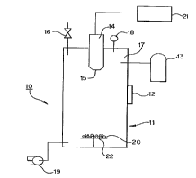
Fig. 1 shows an appa~ us of one embodiment of the present invention
for producing an çnh~n~ed adsorbent and/or e .-hAnced catalytic particle and~or for
5 producing a catalytic particle.
Fig. 2 is a graph showing the redwtion of NO using a particle ofthe
invention.
Fig. 3 is a graph showing the red~lction of CO using a particle of the
invention.
DESCRIPTION OF 1~E PREFERRED EMBODIMENTS
The present invention may be understood more readily by lere~ ce to
the following detailed description of plerel-~d embod;...~ ofthe invention and the
F~mrles included therein and to the Figures and their previous and following
description.
Before the present compositions of matter and methods are disclosed and
described, it is to be understood that this invention is not limited to specific synthetic
methods or to particular formulations, as such may, of course, vary. It is also to be
understood that the terminology used herein is for the purpose of describing partir.,ular
embodim~ntc only and is not intended to be limitin~
It must be noted that, as used in the spe~ific~tion and the appended
daims, the singular forms "a," "an" and "the" include plural rc~elell~s unless the context
clearly dictates otherwise.
In this specific~tion and in the claims which follow, reference will be
made to a number of terms which shall be defined to have the following me~ning~
SUB~ t SHEE~ ~RULE 26)
CA 02227428 1997-10-20
W O96/33013 PCTrUS96/05303
--8--
"Optional" or "optionally" means that the subsequently desc"bed event
or cirr~ nce may or may not occur, and that the description inrllldes in~t~nççs where
said event or circ~m~tAnce occurs and in~tAnCÇS where it does not.
The term "particle" as used herein is used illLe~rl-AI~grAl-ly throughout to
mean a particle in the singular sense or a co",l~il,aLion of smaller particles that are
grouped together into a larger particle, such as an ~lomçration of particles.
The term "ppm" refers to parts per million and the term "ppb" refers to
10 parts per billion. GPM is gallons per minute.
In accordance with the purpose(s) of this invention, as embodied and
broadly described herein, this invention, in one aspect, relates to a method for producing
an f.nhAnred adsorbent and/or enhAnçed catalytic particle and/or for producing a15 catalytic particle, comprising the steps of:
(a) removing an G~G~iLi~, amount of air from a closed cha-"be, co... ~ an
adsorbent and/or catalytic particle, wl~elein the resultant ~h~.. l.~.
p, G~Sul e is less than one atmosphere;
(b) raising the cha",ber plG~:~UlG with an inert gas to at least one atmosphere;(c) contActing the particle with an energy beam of sllffir.irnt energy for a
sufficient time to thereby f l~hAnçe the adso,l,t;nL and/or catalytic
properties of the particle and/or produce catalytic properties in the
particle.
25 The particle produced from this process can have room ttlll~GI~lu~G catalytic capabilities
tov~cuds particular co.,li..nil-~
The invention further provides a method for producing an e-nh~nced
adsorbent and/or çnh~nr,ed catalytic particle and/or for producing a catalytic particle,
30 CO",~,isi,lg implanting oxygen into an adsorbent and/or catalytic particle.
S~IB~ Ult~d~l (RULE26)
CA 02227428 1997-10-20
W096/33013 PCT/US96tO5303
_ 9 _
In yet another aspect~ the invention relates to the particle made by tlhe
process of the invention.
In yet another aspect~ the invention relates to an ~nh~n~ed adsorberlt
5 and/or P.nh~nced catalytic particle and/or a catalytic particle complis-ng an adso-bt~
particle that has been treated to provide an excess of oxygen ;...p~ ed at least on the
surface of the particle to thereby forrn an ~nh~nt~.ed adsorbent and/or ~nh~nced catalytic
particle and/or a catalytic particle.
In yet another aspect, the invention relates to a binder for binding
adsorbent and/or catalytic particles to produce an agglomerated particle colll~li~ill;g
colloidal ~ n;.. ,, oxide and an acid.
In yet another aspect, the invention relates to a method for binding
15 adsorbent and/or catalytic particles, co---~ ing the steps of:
(a) mixing colloid~l ~h~mimlm oxide with the particles and an acid;
(b) ~jt~tin~ the mixture to homogeneity; and
(c) heating the mixt~re for a s -ffi~;~nt time to cause cross-linking of the
mim~m oxide in the mixture.
In yet another aspect, the invention relates to a method for reducing or
eli. . .i n~ ;,-g the amount of a CO~ from a liquid or gas stream co---~-ising
cont~cting the particle ofthe invention with the CO."n...;,~ in the stream for as ~ffirient time to reduce or elin-in~te the amount ofthe co,~ "~ from the stream.
In yet another aspec~, the invention relates to a method for adsorbing a
co"~n...;,~"l from a liquid or gas stream onto an adsorbent particle co---~ i--gcont~cting the particle of the invention with the co"l n~ in the stream for a
s-lffir,içnt time to adsorb the coll~nlllin~
SUBSrrTUlE SHEET (RULE 26
CA 02227428 1997-10-20
WO96/33013 PCTrUS96/0~303
- 10-
In yet another aspect, the invention relates to a method for catalyzing the
degradation of a hydrocarbon co,-.l" ;~ g cont~cting the hydrocarbon with the particle
of the invention for a sllffici~nt time to catalyze the degradation of the hydrocarbon.
In yet another aspect, the invention relates to a method for reducing or
eli" ,i l ,h ~ g the amount of a co"l A " ,; ~ ,l from a gas stream by catalysis compricing
cont~cting the particle ofthe invention with a gas stream ÇOI,Ih;,l;llP a COIIIh~
comprising an oxide of nitrogen, an oxide of sulfur, carbon monoxitle, or n~Lul~s
thereoffor a s lffi~ i~.nt time to reduce or ~limin~te the co"lh".;.-~..l amount.
In yet another aspect, the invention relates to an apparatus for producing
an ~nh~nced adsorbent and/or ~nh~n~ed catalytic particle and/or for producing a
catalytic particle col-lpli~ g.
(a) chamber means for col~lh;~ g the particle in a closed system having an
inlet gas port, an exit gas port, and a target plate, said cl ~llb~l means
being capable of ~h;~llh;~ g vacuum and positive ple~ul~ ;"
(b) means for providing an inert gas to the challlber means through the inlet
gas port;
(c) means for withdrawing from the chamber means an effective amount of
the ~mbient air therein so as to create a vacuum within the ch~n~.
means; and
(d) means for providing an energy beam to the chall,ber means, said energy
beam means outlet being talg~:Led at the target plate.
In yet another aspect, the invention relates to a method for inc.t;a~i,lg the
surface area of an adsorbent and/or catalytic particle, comprising the steps of
(a) raising the chamber gauge ples~ule of a closed chamber co"~ ;l-g the
adsorbent and/or catalytic particle to at least 100 psi with an inert gas
and
30 (b) rapidly decolllpr~s~illg the chamber pres~ul~ to thereby increase the
surface area of the particle.
tTUrE SHEET (RUl~ 26)
_
CA 02227428 1997-10-20
W O96/33013 PCTrUS96/05303
- 11 -
In yet another aspect, the invention relates to a method for producing an
PnhAn~ed adsorbent and/or çnhAnced catalytic particle and/or for producing a catalytic
particle, comprising the step of:
(a) cont~ctin~ an adsorbent and/or catalytic particle with an energy beam of
~lffi~j~nt energy for a s~ffi~ient time to thereby Pnh~n~e the adsorbent
and/or catalytic pl~pGI Lies of the particle and/or produce catalytic
plU~ ies in the particle.
By PnhAnced adsorbe~t and/or çnhAnced catalytic particle, it is int-ontled
that the particles of this invention have improved adsorbent and/or improved catalytic
rop~l ~ies over prior art adsorbent and/or catalytic particles. Also, by producing a
catalytic particle, it is inten-led thlat some particles of the instant invention have catalytic
prope.lies for catalyzing the coll~ ;on of particular COI~IAI~;n~A~ into other forms,
wheleas the same particles not treated by the process ofthe present invention possess no
catalytic plul)el Lies at least for th~ose particular co-~l 'Al~ A~
F.nhAn-~ed adsorptive PIOPGI ~ies is int~n-led to include both ion capture
and ion ~ .A I1ge I l leChA ~ . Ion capture refers to the ability of the particle to bond to
other atoms due to the ionic nature ofthe particle. Ion l ~cl-A~ge is well known in the
art and refers to ions being ill~ .hA l~ged from one substance to another. Adsorption is a
term well known in the art and should be dictin~li~hpd from absol~lion.
In the particle of this ;nvention, typically any particle that initially has
some adsorbent and/or catalytic p-Opel Lies can be used. For PY~Amrle, activated calbon
and oxide particles can be oxygen implanted by the process of the present invention.
For oxide particles, oxides of metals or oxides of non-metals, such as
silicon or ge- ".~ , are pl t;re~ l ed. Even more pl t;r~ d are oxides of transition
metals, oxides of metals of Growp I~[ (B, Al, Ga, In, Tl) and IA (Li, Na, K, Rb, Cs, Fr)
30 of the periodic table, and oxides of silicon. Particularly p- ~rc;c:d oxides include
-Alllmin~lm oxide (Al203), silicon dioxide (SiO2), mAn~nese dioxide (MnO2), copper
Ul~ SHEEr (RULE26)
CA 02227428 l997-l0-20
W O96/33013 PCT~US96/05303
oxide (CuO), iron oxide black (Fe3O4), iron oxide red (ferric oxide or Fe2O3), zinc oxide
(ZnO), zirconium oxide (ZrO2), v~n~ m p~ntQ~ide (V205), and tit~nillm dioxide
(TiO2).
S In one embodiment, the particle comprises ~lllmin~ oxide that has been
pre-treated by a full calcination process. C~lrined ~lllminllm oxide particles are well
known in the art. They are particles that have been heated to a particular temperature to
form a particular crystalline structure. Processes for making c~lcin~d ~lllminllm oxide
particles are well known in the art as disclosed in, e.g., Physical and Chemical Aspects
of Adsorbents and Cafalysts, ed. Linsen et al., ~r.~d~mic Press (1970), which isincorporated by lerelence herein. In one embodiment, the Bayer process can be used to
make ~lllminllm oxide precursors. Also, pre-calcined ~lllmimlm oxide, that is, the
~lllmimlm oxide precursor (Al(OH)3), and calcined ~lllmin~lm oxide are readily
commercially available. C~l~ined Rlnminllm oxide can be used in this dried, activated
form or can be used in a partially or near fully deactivated form by allowing water to be
adsorbed onto the surface ofthe particle. However, it is p,G~l~ble to r..;l~;i..;,~ the
deactivation to l~-AX;~ 9 the adsorbent capability.
In a ~lere"ed embodiment, the ~lllmimlm oxide has been produced by
20 c~ ning at a particle temperature of from 400~C to 700~C. These p,ere"t;d ~lllmimlm
oxide particles are l~l eft;l ~bly in the gamma, chi-rho, or eta forms and have a pore size of
from 3.5 nm to 35 nm di~meter and a BET surface area of from 120 to 350 m2/g.
For activated carbon, any of the activated carbons useful in the adsorbent
25 art can be used. Preferably coal based carbon or coconut based carbon are used.
Generally, coal based carbon can be used to rçm~ te aqueous co, .l ;. ,~ c whilecoconut based carbon can be used to rlom~ te airborne or gaseous co"~ ,;"~
Plere,~bly, the activated carbon is less than 20 microns in size for ease of mixing and
extrusion.
SU~lllult~h~to (RU~E26)
-
CA 02227428 1997-10-20
WO96/33013 PCT~US96/053~3
-13-
The particle of the invention can be used alone, in co,l,~ aLion with
identic~l or di~ele~lL type compositiom particles plepa.ed by the p.ocesscs ofthe
invention, and/or in colllbilla~ion with other adsorbent or catalytic particles known in the
art. The particles can be combined in a physical mixture or agglolllel~LLed using
S techniques known in the art or d;sclosed herein. In a plcrélled embodiment, d;~ercllL
composition type particles are combined by a~glomrration to form a mllltifilnctiona
composite particle. In this embodiment, particles can be used to achieve mllltiple
fimr.tion~ simlllt~neously, such as by removing multiple co~ , by taking
advantage of the individual effects from each of the types of particles. Co-particles that
10 are preferably used in this invention include all particles previously disclosed and zeolite.
In one embodiment, the composite particle col,l~lises ~ ",;"~". oxide
and a second particle oftit~ni--m dioxide, copper oxide, v~n~tli-lm pentoxide, silicon
15 dioxidr~ g~l-ese dioxide, iron oxide, zinc oxide, activated carbon, or zeolite. In
another embodim~nt, the composite particle colll~,ises ~lllmimlm oxide and activated
carbon. In another embodiment, the particle co",~u,ises activated carbon (coal-based?,
activated carbon (coconut-based), silicon dioxide, and ~lllminllm oxide. In a pleîellèd
embodiment, this particle is used to le~.,e~liA~e aqueous co"l~",;..~lion In one20 embodiment, this particle of coal-based activated carbon, coconut-based activated
carbon, silicon dioxide, and alllrninllm oxide is used to rome~ te aqueous co~lA~
such as 1,2-dibromo-3-chlol opl opane (DBCP), radon, and heavy metals, from a
co,~lA,n;,~ted water source.
The particles of this invention can be subjected to other surface
tre~tmrnt~ prior to or after being treated by the process of the present invention. The
particles of the invention can be pretreated by processes known in the art to illlplo~,e
their adsorptive capability, such, as by r,~lr.in~tion ~lrin~tion refers to heating a solid
to a temperature below its melting point to alter the crystal structure to a particular
- 30 form. The calcinated particle can be dried or ,~,~."~ ed in dry form cle~Lll~, an
activated particle or, if water is absorbed on the particle, the particle can be partially or
ult!;llE~ULE26)
CA 02227428 l997-l0-20
WO96/33013 PCTrUS96/05303
-14-
near fully deactivated. In one embodiment, the particles of this invention can be in dry,
slurry, or gel form. The particle size can vary depen.lillg on the end use, rangin8 in sizes
known in the art, such as collQi(l~l, microscopic, or macloscopic. Preferably, the
particles prior to agglomeration are less than 20 microns in size for ease of mixing and
5 extrusion.
Binders for binding the individual particles to form an agglomel~Led
particle are known in the art or are described herein. In a ~l~relled embodiment, the
binder can also act as an adsorbent and/or a catalyst. A plerell~d binder for the
10 agglomerated particle is colloidal alumina or colloidal silica. At approx;,.~ o,ly 450~C,
the colloidal ~ min~ goes through a tran~rullll~Lion stage and cross-links with itself.
Colloidal silica cross-links with itself if it is s -ffiçiently dried to remove water.
Preferably, from about Z0 wt. % to about 99% of the total mixture is colloidal ahlmin~
or colloidal silica to provide the nece~ry cros~ ki~-g during heating to bind the
15 agglomerated particle into a water-re~ ~lL particle. The particle can then w; exposure to all types of water for an ~oytentled time and not degrade.
In one embodiment, the agglomerated particle is made by mixing
colloidal ~lllmin~ with the adsorbent particles. Typically, from about 2p% to about 99%
20 by weight ofthe mixture is colloidal alllmin~ The particle mixture is then mixed with an
acid solution such as, for example, nitric, sulfuric, hydrochloric, boric, acetic, formic,
phosphoric, and ., i~Lu. es thereof. In one embodiment the acid is 5% nitric acid
solution. The colloidal ~lllmin~ adsorbent particles, and acid solution are thoroughly
mixed so as to create a homogenous blend of all elem~nts Then addition~l acid sol~ltion
25 is added and further mixing is performed until the mixture reaches a suitable con~i~ten(cy
for agglomeration. After agglomeration is complete, the agglomerated particles are
heated to at least 450~C to cause the colloidal alumin~ cro~clinkin~ to occur.
Sources and/or methods of making the starting materials for the various
30 adsorbent particles of the present invention are readily available and are well-known to
those of oldill~y skill in the art.
SUBSII~u~hk~l ~RULE26~
CA 02227428 1997-10-20
W O96/33013 PCTÇUS96/05303
-15-
For an explanation of the process used to make a particle of one
embodiment ofthis invention, reièrence is made to Figure 1. The app~ s ofthis
embodiment is dçcign~te(l generally as 10 The particulate m~tPri~l or target medi~ 20
to be treated is placed in a chamber 11 on ungrounded target plate 22. In one
- S embodiment, the target plate can be rotated to provide more efficient ~ of the
particle by the energy bearn. Chamber 11 is preferably made of a dielectric material
Chamber 11 is sealed by a col..~l es~ion plate latched door 12 that has the ability to
wi~ rl high co...~.es~ion ratios both in the positive as well as negative pressures
Pressure is ~--o- ilo-t;d with pressure gauge 18. Vacuum con~lition~ are created in the
10 chamber using vacuum pump 19 to evacuate an effective amount of air initiallyco~ ed in the cl.~".her. Air can be dt~ ,.-Lal to the oxygen i---pl~-~a~ion step in that
it reduces the ~fficiçncy of the energy beam's affect on the particle Evacu~tin~ an
effective amount of air is intçntled to mean that enough air is removed so that the energy
beam has the ability to çnh~nce the adsorbent and/or catalytic plop~llies and/or produce
15 catalytic plu~Jel Lies in the particle. Typically, vacuum pump 19 is used to evacuate as
much air as possible from çh~mherll to ~nX;~ ; the energy beam's efficiency an~ to
allow a beam of lower energy to be used The ch~--ber is brought up to a pre~ul~ of at
least atmospheric pressure using an inert gas from cylinder 13 through a high p.~s~ure
injector 17. In one embodiment, the gauge pressure (pressure above atmospheric) is
20 from 1 to 5,000 psi Typically, the gauge p-e~su-e can be at least about 20 psi to
prevent arcing.
The inert gas is typically any gas that is inert to ç~Pmic~lly reacting with
and degrading the adsorbent palticle, and yet, does not impede the energy beam's25 effectiveness in implanting the oxygen. Typical inert gases include the noble gases, such
as helium, neon, argon, krypton, xenon, and radon
The energy source is targeted at the particle co~ ined in the ch~--ber
through an energy injector 1~ located at the end ofthe energy source 14 The energy
- 30 source can be of any high energy that can force oxygen into the particle andJor add
excess charge to the particle Typically, the energy source is an ion m~çhin~ which
SUBSTITUTE SHEET (RULE 26)
CA 02227428 1997-10-20
WO96/33013 PCTrUS96/0~303
-16-
CQnCe~ leS an ion or electron beam, such as a broad beam ion source or a wide beam
photoinni7tor. In a specific embodiment, the energy source can be a broad beam ion
source, m~nnf~ctllred by Commonwealth, ~c~ , Virginia, U.S.A. having a
n output of 25 eV. The energy source 14, utilizes a power supply 21. In a
5 specific embodiment, the power supply can be a Commonwealth IBS-250 high voltage
power supply rated up to 1500V with remote operation c~p~hiliti~s A~ itio~lly, the
energy beam causes the inert gas to become ionized. The charge introduced into the
chamber is at a level s~lfficiçnt to enh~nre the adsorbent and/or catalytic properties of
the particle and/or produce catalytic p, O~l Lies in the particle. In one embo-liment, an
10 cle~iLlon beam of 15 to 20 eV was used, although a smaller or larger amount of energy
can be used. Once the proper charge has been ~tt~ined for a sllfficient time, the energy
source is turned off. This sufficient time can be very short, on the order of less than a
second to about 10 secon~ls, although a longer time is not d~ t&l. Then, the
cl,~"l)el pressure is deco,n~ sed via a release valve 16.
Not wishing to be bound by theory, it is theorized that the energy beam
causes monoatomic oxygen present on the surface of the particle to be pushed below the
surface of the particle, which then becomes tightly bound to the internal structure of the
particle. For crystalline particles, the oxygen beco,l,es tightly bound within the crystal
20 lattice. The monoatomic oxygen originates from oxygen that is on the outer surface of
the crystal lattice of the particle or from residual water or air on the surface of the
particle. This increases the adsolbenl and/or catalytic characteristics of the particle and
can create catalytic propt;,L,es, inçl~lrlin~ room tt;""~ L-Ire catalytic capabilities, in the
particle. It is additionally ~l,eoliGed that the advantageous p,~pelLies ofthe particle of
25 this invention result from the energy beam adding an electrical charge or in~ ased
electrical charge to the particle.
In another embodiment, in the energy beam proces above, after the air
has been removed from the chamber, inert gas is added so that the chamber pressure is
30 brought up to a high pressure. Typically, the gauge pressure can be from about at least
100 psi, more p,~lably at least 1,000 psi, even more ple~l~bly at least 5,000 psi.
Sl~a~a~J~k~t~ (RULE26)
CA 02227428 1997-10-20
W O96133013 PCTrUS96/05303
-17-
Even higher p. es~u- GS can be used if the cllalllbel 15 of a high enough pressure rating.
The high pressure or co...~.ession is ~ ed for a sllfficient time to increase the
density of the particle. Residual air is bled from the vessel, thereby removing any
residual air from a puffed up parl:icle~ until a consla.,~ pressure can be .. ~;"l~ d
S Typically, about ten minutes of hligh pressure is sl lffic i~nt After the energy source has
been introduced for a sllffiri~nt time in the chamber as described above the energy
source is turned off and then the chamber pressure is rapidly decolnp, ~ssed via release
valve 16. By rapidly it is plerG ~bly meant about 3 seconds. This increases the surface
area of the particle.
Not wishing to be bolmd by theory it is tl~o, ;7Pd that as the prGs~ulG
from the chambel is rapidly released, the co"~e"~s ofthe chamber expand ~imlllt~nçously
but at di~GIGllL rates of c ~ ;on. The charged inert gas PYp~n~l~ at a much faster rate
than that of the particulate matter due to the density differences between the two
15 subsl~lces. Due to this PYp~n~ion rate diLrGlGllce the charged inert gas travels rapidly
and penetrates or explodes into and ~hrough the particles. This rapid pel,~ ion alters
the pore structure and increases the amount of pores of the particle. The surface area of
the particle is thereby greatly hlc.Gased hl.;,~iasi"g the overall adsorption capability of
the particle. Depelldi..g on the particle employed the BET surface area can be incl eased
20 at least 1% more preferably at least 5% even more preferably at least 10% even rnore
preferably at least 20%, even more plerGI~bly at least 30%. The lower density particles
such as activated carbon, can achieve a greater inclGase in surface area.
The ch~--ber p-essu.~ and the energy level can be varied to produce
25 di~ren~ effects to meet the par~icular physical and ch~mic~l req~,i,e",~"~s for the
specific particle end use. Varying the pl es~u- G and energy level p~ ~lllGLG. ~ can alter the
ability ofthe particle to adsorb a particular co"l;l",;" ~"1
-
In another embodiment of this invention the surface area ~nh~n~em~nt
- 30 aspect of the process can be practiced alone without the energy beam aspect. In this
embodiment, the inert gas only needs to be inert to the particle and does not have to be
S~ u~t ~hstl tR~l,E 2B~
CA 02227428 1997-10-20
WO96/33013 PCTrUS96/0~303
-18-
inert to the effects of the energy beam. Thus, gases such as air and CO2 can also be
used in the this embodiment.
In another embodiment, the energy beam aspect can be practiced alone
5 without the surface area ~nh~ncçmPnt aspect. In this embodiment, the energy beam is
targeted directly at the particle to implant oxygen within the particle. This can be done
in the batch process described above or a semi-batch or contin--o -~ process. In a semi-
batch process, particles are ~--tom~tic~lly moved into the ch~mhçr where they are
treated and ~utom~tic~lly removed from the ch~~ er. In a contin~o~ process, in one
10 embodiment, the particles are provided on a collve:yor belt system. Air is displaced from
the area around the particles by inert gas to provide a viable path for the energy beam,
which is set up along side or overhead of the conveyer belt system. The energy beam is
either continuously on or is turned on as the particles reach a specific point along the
conveyer belt system. In a variation of the embodiments of this invention, the air
15 removal and repl~cPm~nt with inert gas steps in the batch or semi-batch processes and
the air tli~pl~cP~mpnt by inert gas step in the continuous process can be avoided by using
an .,,~LIel.lely high level of energy source, such that, the air does not impede the oxygen
from penetrating the surface of the particle. In another embodiment of a contim~o~s
process, the particles are filtered through a mesh screen sieve, which has been
20 subst~nti~lly ionized to cause the oxygen on the particle to pen~ e the particle.
The particles of this invention are characterized by having an incl eased
level of oxygen at least on the surface of the particle. This increased level of oxygen is
higher than the total of the stoichiometric amount of oxygen eYpected in the particle and
25 that found as residual oxygen on the surface of the particle. The oxygen impl~nted
particle has at least 1.1 times the oxygen atom per cent to non-oxygen atom per cent
ratio at its surface colll~t;d to the initial non-oxygen ;",pl,."led particle, vvhelein the
surface characterization is determined by an x-ray photoelectron spectroscopy (XPS or
ESCA) specLIullleLer, a device well known to those of skill in the art. Even more
30 plerel~bly, the particle has at least a 1.5 fold increase in oxygen ratio, even more
preferably the particle has at least a 2 fold increase in oxygen ratio, even more
SUB~ ttl (RUlE26~
CA 02227428 1997-10-20
WO96/33013 PCTrUS96/05303
- 19-
preferably, at least a 4 fold increase in oxygen ratio, even more preferably at least a 6
fold increase in oxygen ratio.
The particle of this i~vention can be used in any adsorption and/or
S catalytic app~ tion known to those of ol.lin~y skill in the art to achieve supclior
results over prior art particles. ~ ition~lly, the particle of the invention can be used in
various adsorption and/or catalytic applications never before co.~le~ .lated in the art. In
one embo~lim~1lt~ the particle is used for environm~nt~l le~"e~ ;Qn applications. In this
embo-lim~nt the particle can be used to remove c~."l~.";~-~..le such as heavy metals,
10 organics, in~h1din~ for example but not limited to, chlorinated organics and volatile
organics, inorganics, or .",~lU,t;s thereof. Specific eY~mples of ccs..l~...;l-~..l~ include,
but are not limited to, acetone, microbials, ~.. oni~ benzcne, carbon monoYide,
chlorine, diox~ne, ethanol, ethylene, formaldehyde, hydrogen cyanide, hydrogen sulfide,
nol, methyl ethyl ketone, methylene chloride, nitrogen oxides, propylene, styrene,
15 sulfur ~io~ide~ toluene, vinyl chloride, arsenic, lead, iron, phosphates, s~l~nil-m
c~-lmi--m, uranium, ph~toni-lm radon, 1,2-dibromo-3-chloloplùpalle (DBCP),
chromium, tobacco smoke, and cooking fumes. The particle of this invention can
r~me~ te individual co"l~""~ or multiple co"l~",;~-~"l~ from a single source.
Foren~ ulllll~ ,,e~ napplications,typically,particlesofthe
invention are placed in a colllail]lel, such as a filtration unit. The co"~ ";l,~led stream
enters the col,~ er at one end, contacts the particles within the co~ er~ and the
purified stream exits through another end of the con~ailler. The flow rate of the
co"l ~ ,-l stream and the amount of particle m~teri~l needed can be determined by
one of skill in the art with routine expe, ;" ,~ l ;o~ by dt:lt;""il~ing the capacity needed.
The particles contact the co,.l~ within the stream and bond to and remove the
co"li1",i~ n from the stream. The particles can also ~limin~te certain co,,l~ bycatalyzing the conversion of the co~ into other components. Typically, in the
adsorption application, the particles become saturated with co~ ,lc over a period
- 30 of time, and the particles must be removed from the container and replaced with fresh
particles. The co~ l stream can be a gas, such as air, or liquid, such as water.
SUBSl~lU~ t~l (RULE26)
CA 02227428 1997-10-20
W O96/33013 PCTrUS96/05303
-20-
In the adsorption application, the particle of this invention bonds with the
co,~A~ so that the particle and co~ n~ A~.I are tightly bound. This bonding makes
it difficult to remove the coi~",il-A~.~ from the particle, allowing the waste product to
either be disposed of into any public landfill or used as a raw material in the building
S block mAm-f~ctl-ring industry. Measu,el"ents of CQ.I~ adsorbed on the particles
of this invention using a Toxic Chemical TeA-.hAte Permit (TCLP) test known to those
of skill in the art showed that there was a bond at least as strong as a covalent bond
between the particles of this invention and the col ,l ~ ~ ";, ~, ,I s
The particles of this invention have superior ability to adsorb
co,.l~ "l~ due to ~nh~nf~ed physical and çl.~".;çAl prc.pe,lies ofthe particle. The
particles of this invention can adsorb a larger amount of adso,l,aLe per unit volume or
weight of adsorbent particles than a non-Pnh~nced particle. The particle of thisinvention surprisingly removes conl~,,inAlll~ in various streams at both high and low
15 conc~ ,l, aLions of CG- ll ~ . . .i l~zi. .l ': Also, the particles of this invention can reduce the
conce"~,~lion of co~ A~ or adsorbate material in a stream to a lower absolute
value than is possible with a non-çnh~nced particle. In particular embo-lim~nts, the
particles ofthis invention can reduce the co..l~ .l conce"L,~Lion in a stream to below
detectAble levels, never before achievable with prior art particles.
The particles of this invention can also have a newly added catalytic
property. Specifically, the increased oxygen content in the particle matrix allows the
particle to act as a catalyst. For example, the particle has the ability to catalyze the
break down of hydrocarbon compounds and has the ability to catalyze the conversion of
25 CO, SOx, or NOX into other components, even at low heat or room t~lllpel~ules.
Particular end uses co, ,l ~ ,rl~ted by this invention include, but are not
limited to, reducing or ~limin~ting col-lA~ c for particular applications, such as
waste water ~,e~l~"~"l facilities, sewage f~ lities~ mllniçirAl water purification fA~ilitif-c,
30 in-home water purification systems, smoke stack ~m~lçnt~, vehicle exhaust ~ ents,
engine or motor çffl~lçnt~, home or building air purification systems, home radon
SUB~ u~ SHEEr (RUIE 26)
CA 02227428 1997-10-20
WO96/33013 PCTrUS96/05303
-21-
lf~"-e~ tions, landfill le~ch~te~, m~mlf~ctllring facility rh~mic~l waste .offlllPnt~ and the
like.
-
Prior art adsorbents, such as activated carbon, when sprayed with anti-
microbials, tend to lose their adsorbent properties. Conversely, the increased adsolbt:-"
properties allow the particles of the present invention to be sprayed with anti-microbials
while still, ~ g the particle's adsorbent prope, lies. Moreover, unlike prior art
particles, contact with water doex not deactivate the adsorption capability of the
inventive particles.
Expel illlt;lllal
The following ~y~mrles are put forth so as to provide those of o,dh~y
skill in the art with a complete disclosure and description of how the co",~ou,lds claimed
herein are made and evaluated, and are intçntled to be purely ~ .y ofthe invention
and are not intçnded to limit the scope of what the h~venlo~ regard as their invention.
Efforts have been made to ensure~ accuracy with respect to numbers (e.g., amounts,
temperature, etc.) but some errors and deviations should be accou"Led for. Unless
in~1ic~ted otherwise, parts are parts by weight, temperature is in ~C or is at or near room
te"")e,~lu,c; and pressure is at or near ~tmospheric.
Example 1.
Various particles were made in accordance with the procedures of this
invention as follows. The procedures used to prepare the particle dçcign~ted as la in
Table 1 below, having a composition of 60% A12O3, 20% carbon, 15% m~n~nese
dioxide and 5% copper oxide, is ~Yçmplified The ~lllmin~ utilized was a gamma
c~l-.ined (550~C) ~ min~ derived from a high density, low porositv pseudoboehmite
min~ or ~ min~ gel. The alumina was pretreated by c~l~ining to 550~ C to reach the
-30 desired gamma crystalline structure. The carbon utilized in this particle was a coconut
based carbon, design~ted as Pol~mesian coconut based carbon purchased from Calgon
SU~IllultSntltl I~RUIE26)
CA 02227428 1997-10-20
W O96/33013 PCTrUS96/05303
-22-
Carbon Corporation. Due to the use of coconut shells in the m~mlf~ctllre of this carbon,
there exists a very large surface area as well as micro-pores which are useful for
"~ing co~ in a gas stream. The four individual particle types were mixed
together in their appl op, iate weight per cents accor.l;"g to the dry weight. They were
S mixed together into a homogenous dry mixture. An acid sollltion of 20parts by weight
of 80% nitric acid was added to 80 parts by weight of water. The acid solution was
added to the dry particle mixture slowly until the mixture obtained a moist pasty
co~ lç~ y. This con~i~tçncy allowed the mixture to be extruded into the desired forrn.
The mixture was extruded using a LCI model BTGa9 laboratory extruder. After the
10 mixture was extruded, the extrudate was chopped up into app,."~i",alely one-si~ee"l
to one-eighth inch particles and then was dried at a temperature of at least 450~ C to
cross-link the ~ mimlm oxide. The particles were placed in a vacuumlpressure vessel
ch~"ber on an ung~oullded target plate. The door to the ch~"ber was secured, and air
was pumped out of the ch~nbel down to a negative p,~.sa..le of two militorrs. Upon
15 reaching this pressure, argon gas was allowed to bleed into the chamber and reach an
internal gauge plesaur e of about 20 pSi. Upon reaching this pressure, the energy beam
source was activated to 15 to 20 eV and was applied to the particle on the target area.
A Co"""o"wt;alth broad beam ion source was used. Tl~ .e.~l times for the particles
vary according to the amount and density of material on the target. For this example, a
20 volume of 50 grams of material was used and a tre~tm~nt time of ten seconds was used.
The ~ times also vary according to the output power from the energy beam
source and the internal pressure in the chamber. After ten seconds, the ion source was
turned off and the chamber was evacuated to atmospheric pressure. The sample wasthen removed from the cha",be,.
Particles lb through lac were similarly made in accordance with the above-
described example for 1 a except that the particular compositions were as set forth in
Table 1. Also, the carbon utilized for aqueous particle de~i n~tions lv and lw was a
coal based carbon. This coal based carbon was purchased from Calgon Carbon
30 Corporation as WHP grade carbon. The particular alumina utilized in particles lb
through lac was the sarne as described above for particle la, a gamma s~ ined ~ nnin~
SUB~ lllt~t~l (RUlE26)
CA 02227428 1997-10-20
W O96/33013 PCT/US96/05303
-23-
The other components listed below in Table 1 are well known and are readily available
to one of skill in the art.
-
~Each of the particle's composition made in accordance with the
5 procedures ofthis invention described above and the co.~ it was tested with inExamples 2 and 3 are listed below in Table 1. The same particle dç~ tion system is
used in Tables ~-3.
S~ a~ UlE 2~
CA 02227428 1997-10-20
W 096/33013 PCT/US96/05303
-24-
TABLE 1
PARTICLE COMPOSlTIONI CONTAMINANTS
DESIGNATION (weight %)
AIRBORNE AQUEOUS
I a 60% Al2O3,20% Carbon,15% Acetone
MnO2, 5% CuO
Ib 100% Al2O3 Ammonia
Ic 50% Al203,40% Carbon,10% Beuzene
sio2
Id 40% Al203,30% V205,20% Carbon M~.. tlf
MnO2,10% TiO2
le 100% Al2O3 Chlorine
lf 100 % Al2O3 1,4-Dioxane
I g 100% Al2O3 Ethanol
Ih 100% Al203 Fc, ---al~h~
li 40% Al2O3,30% MnO2,20% Hydrogen Cyanide
V2O5,5% Zeolite,5% Fe2O3
Ij 30% Al203, 50% MnO2,5% Hydrogen Sulfide
Carbon,5% SiO2,10% ZnO
Ik 90% Al203,10% Carbon M~t~ ,1
11 100% Al2O3Methyl Ethyl Ketone
lm 40% Al203,20% MnO2, 10% M_ll.jl~,.. ~, Chloride
CuO,30% V2O5
In 40% Al2O3,30% V2Os.20% Nitrogen Oxides
MnO2.10% TiO2
lo 30% Al203,70% Carbon Plu~ e
Ip 30% Al2O3, 70% Carbon Styrene
1 q 100% Al2O3 Sulfilr Dioxide
Ir 40% Al2O3,30% MnO2,30% Toluene
Carbon
ls 30% Al203,70% Carbon Vinyl Chloride
lt 100% Al2O3 Arsenic
lu 100% Al2O3 C- '
lv 40% Al203,40% Carbon,20% Chlorine
sio2
SUBST~TUTE SHEET (RULE 20~
CA 02227428 1997-10-20
W O96/33013 PCTrUS96/05303
-25-
TABLE1
PARIICLE COMPOSrrIONl CONTAMDNAN~
DESIGNAIION (wei~t%)
AnRBOFU~E AQUEOUS
Iw 40% A1203, 40% Carbon,20% DBCP
sio2
Ix 100% A1203 Iron
00% A12~3 Lead
Iz 100% A1203
1aa 40% A1203, 40% C~bon,20% Radon
sio2
lab 100% A1203 Seleniurï
lac 100% A1203 Ural~ium
Activated carbon coconut based was used for the airborne
co..li..,.;..~,.l~ and for laa (radon) and &_liv~led carbon
coal based was used for ~queous co.~ lv and lw.
E;sample 2.
The particles made in F.~mple 1 were tested for their ability for removal
10 of various components from air. The tests for the a;ll,ullle co..l~ as sulll~ ed
in Table 2 below were performed as follows. The co..l,....;..~ source used was either
solvent vapor or an offthe shelf bottled gas mixture. Solvent vapor was mixed with
humid air by injecting into the systern with a syringe pump. A gas bottle with a needle
valve and a flow meter, either a rotarneter or a mass flow meter controller, was used to
blend the gas bottle effluent with the humid air. Humid air at 30% relative humidity and
25~C was mixed with either the solvent vapor or gas stream. The humid air was
~enelaled by a flow-ttlll~ L.Ire-humidity control module which controlled
temperature, relative humidity and the flow rate of the humid air. The concel~ lion of
the airborne co..~ l in the humid air was then Illea~u,ed by an infrared analyzer.
After the influent infrared analysis, the sarnple entered a sarnple holder. The sample
holder was a three-inch tli~meter test vessel, which held a 200 gm amount of particle
sample in place using a fritted disk. After passing through the particles, the
concellll~lion ofthe co~ ...in~ in the effluent exited the sample holder. The
SUBSrtTlrrE SHEET (RULE 26~
CA 02227428 1997-10-20
W O96/33013 PCTrUS96/05303
-26-
co~ P .l . ~lion of the CQ~I A ~ ~ ~' 1~- ~1 in the effluent side of the particle sample holder was
also analyzed with an infrared analyzer. The test time was ten mim-tçs Percent removal
was c~lcc~ ted as (initial coi.l~",;,~A~.I concentration minus effluent co,~ h~
collcenL-~lion) divided by initial col,l~,..;l-~,l conce..L.~lion.
S
The results are set forth in Table 2 below.
TABLE 2
INITIAL
PARTICLE AIRBORNE CONTAMINANT PERCENT El.OW
DESIGNATIONCONTAMINANT CONCENTRATION REMOVAL RATE~
(ppm)
la Acetone 750 100 40 Ptlmin.
Ib Ammonia 50 100 40 ~/min.
Ic Benzene 50 100 40 R/min.
Id CarbonM nr~Yi~l~ 10000 100 40ft/min.
le Chlorine 34 100 40 ~/min.
If 1,4-Dioxane 50 100 40 ft/min.
Ig Ethanol 1000 100 40 ft/min.
Ih Ful.. lald~,h~ 10 100 40 ft/min.
Ii Hydrogen Cyanide 20 100 40 ft/min.
Ij Hydrogen Sulfide 20 100 40 ft/min.
Ik Methanol 200 100 40 ft/min.
Il Methyl Ethyl 1000 100 40 ft/min.
Ketone
ImM~,llljl~,.-~, chloride 50 100 40 ft/min.
In Nitrogen Oxides 100 100 40 ~/min.
Io Flu~ , 700 100 40 flL/min.
Ip Styrene 50 100 40 ft/min.
Iq SulfilrDioxide 20 100 40ft/min.
Ir Toluene 100 100 40 ~/min.
Is Vinyl Chloride 20 100 40 ftlmin.
40 flL/min velocity was 55.5 I/min volumetric flow.
SUESll~u~ tl (RULE26~
-
CA 02227428 1997-10-20
WO96/33013 PCTrUS96/053a3
-27-
In Table 2 above, for the formaldehyde test using particle lh,
formaldehyde was not detected on the particle after the test was completed and, as
shown in Table 2, no formaldeh~de was detected in the ef~luent stream. This particle lh
acts as a catalyst towards formaldehyde and breaks down the formaldehyde into what is
5 believed to be CO2 and water, e~en at room t~l~lpel~L~Ire. This was further evidenced by
a separate test in which it was shown that the formaldehyde was removed from thesystem over a subst~nt~ y longer period oftime than can be ~ ;..ed if the particle
acted only as an adsorbent.
As can also be seen from the above Table 2, carbon monoxide and
nitrogen oxides were not detected in the effluent system. Because these two
components do not normally adsorb to the particle of the type used in this test, these
particles act as a catalyst towards CO and NOX. It is believed that the CO is converted
to CO2 and water and the NOx are collvelled to N2 and ~2- It is also believed that the
rçmetliAtiQn of SO2 was through, at least in part, a catalysis reaction that converted SO2
into other components. The catalyzed re~ction~ were surprisingly achieved even a~
room te""~e, ~tu, ~.
E~ample 3.
The particles made in F.Y~mple 1 were tested for their abilit,v for the
removal of various components from water. The test procedures were as follows. For
each co,.~ A1~ run, 5 glass columns of 0.875 inch inner ~ meter by 12 inches long
were prepared, each having a bed volume of test particle of 95 mls. Each bed wasflushed with five bed volumes of deionized water by dow"w~d pumping at 6 gpm/ft2 of
cross-sectional fiow rate (i. e., about 95 mVmin). Each of the flow rates listed in Table 3
is per foot squared of cross-sectional flow rate. Test solutions for each of the aqueous
co..~i..-.;"~"l~ were prepared. A total often bed volumes, that is, about one liter per
column of aqueous co"~ A"~ test sollltion~ was pumped through each ofthe columns.
- 30 During each lun, the aqueous coll~";l~ test solutions were continuously stirred at
low speed prior to entry into the glass column to ".~ ;l, a homogenous composition.
SU~ u~ EEl (RULE2B)
i CA 02227428 1997-10-20
WO96/33013 PCTrUS96/05303
-28-
During the tenth bed volume, an effluent sample from each column was csllected and
analyzed for the particular aqueous c~ ,..,.;"~"l ~Mition~lly, a single influent sample
for each test was collected and analyzed for the col,~n,ll;ll,.,ll conce-lLl~ion.
The results of these tests are set forth in Table 3 below.
TABLE 3
PARTICLEAQUl~OUS
DESIG- CON- INFLUENT EFFLUENT li LOWDETECTION
NATIONTAMINANT RATE LIMll
lt Arsemc 2,890 ppb < 10 ppb 5-6 GPM 10 ppb
lu Cadmium 1,003 ppb c10 ppb 5-6 GPM 10 ppb
Iv Chlorine 263 ppb <10 ppb 5~ GPM 10 ppb
Iw DBCP (sw) 230.0<0.02 ~g/l 5~ GPM0.02 ~g/l
1,2-Dibromo- ~gA '0.02,ug/l 5-6 GPM0.02 ~g/l
3- (sw) 210.0<0.02,ug/1 5-6 GPM 0.02
Chlulu~u~
(gw) 0.07
~g/l
Ix Iron 1.15 m~/l<0.03 mg/l 5~ GPM0.03 ~g/l
ly Lead 215 ppb < 10 ppb 5-6 GPM 10 ppb
Iz P~ h t. ~ 40.45 mg/l 9.50mg/1 5-6 GPM N/A
laa Radon 1,104.2 303.2 pCi/l 5-6 GPM N/A
pCi/l 306.1 pCi/l 5-6 GPM
911.6 pCi/l
I ab Selenium 1.45 mg/l< 0.003 mg/l5-6 GPM0.003 mgtl
lac Uranium 50.5 ppm 0.08 ppm 5-6 GPM N/A
sw = Synthetic water
gw = ground water
E~cample 4.
A particle of 100% activated carbon coconut based of the present
invention was prepared in accordance with the procedures of Example 1 above. An
S ESCA specl. u.lle~er was used to analyze the surface composition for the original
~SmUTE SHEET (RIJLE 26)
CA 02227428 1997-10-20
WO96133013 PCTrUS96/05303
-29-
activated carbon particle and the particle after it was prep2LIed using the process of
F.Y~mrle 1. The surface char~ct~i7~tiQn results are as follows.
J 5 TABLE 4
ACTIVATED CARBON
INllrL~L ACTIVATED PARlICLE OF TEIIS
li T F.l~F.l~T CA]RBON PARTICLE INVENTION
(Atom %)(Atom %)
Carbon 96.47 61.65
Oxygen 3.53 16.37
Sodium 0.59
Fluorine 8.61
Potassium 7.60
Chlorine 1.61
Sulfur 0.86
Phosphorus 0-55
~ "~c;."" 2.5
Thus, the initial particle had an oxygen/carbon ratio of about 0.04,
whereas the treated activated carbon particle of this invention had an oxygen/carbon
ratio of about 0.27, for an increased oxygen/carbon ratio of about 7 times the original
ratio. A similar test was run on 100% ~ mimlm oxide p,ep~ed accolding to the
process of Example 1. The oxygen/~ min--m ratio was inclt;ased at least about 2 fold
over the original untreated particle oxygen/~ ratio.
Example5.
A TCLP test was run on two di~,e"~ co.~f ~ reme~ tinn
applications ofthis invention. The particles were p,~pa,ed by the procedures of
Fx~mple 1 and were used to adsorb the particular co.~ in Table 5 below. In
accordance with the EPA test rnethods, the particles were, inter alia, washed with an
SUBSr~ SHE~T ~RI~LE 26~
CA 02227428 1997-10-20
W O96/33013 PCTrUS96/05303
-30-
acid solution and tumbled for the requisite length of time. The conce..L.~lion of the
co~ removed from the particle were then measured. The results are set forth
below in Table 5.
TABLE 5 '-
EPA TCLP TCLP
PARTICLE CONTAMINANT TEST CONTAMINANT PQL
METEIOD (mg/l)
100%AI203 Lead 1311/6010 C0.50 0.50
100% Al2O3Phosphate 1311/365.4 <o.l2 0.1
PQL is the practical qu~ntit~tion limit, which is an EPA
standard, and is di~e.t.-l than the lowest detect~kle limit.
2 TCLP measures for phosphorus.
Thus, the particles of the invention, when acting as an adsorbent, bond tightly to the
COIIInllljl~hlll~
20 Es~mple 6.
A fixed bed reactor was charged with 158 g, 9.4 cubic inches (2 inches
di~met~r x 3 inches high) ofthe particles of F.x~mple l(d) (40% Al2O3, 30% V205, 20%
MnO2, 10% TiO2). A mixture of 101.8 ppm NO and 1,035 ppm CO in air was fed into
25 the fixed bed reactor at room tel.~e ~lule at a rate of 35 standard cubic feet per hour
(SCFH). The efrluent of the fixed bed reactor was fed into a Horiba CLA-510SS NOX
analyzer and a VIA-510 CO analyzer. The NO concentration dropped imm~di~tely
reaching 5.4 ppm by 5 minutes (the first recorded measurement) and continlled to drop
to 4.0 ppm by 40 min. (See, Figure 2). The CO conc~ntration d.opped more slowly,30 drol)pi-lg to 532 ppm at 40 min. (See, Figure 3). The test was stopped shortly after 40
minllt~e The CO concenl-~lion was still dec-easi-lg at 40 min. and may decrease further
Sl.IBSTl~UI E SHEET (RULE 26)
CA 02227428 1997-10-20
W O96/33013 PCT~US96/05303 -31-
upon further reaction time. It is believed that the particles of the invention catalytically
degrade the CO and NO.
Throughout this applic~tion~ various public~tiQne are lc;relenced. The
5 tlieclos lres ofthese public~tione in their entireties are hereby h~col~ul~Led by r~rt;lellce
into this application in order to more fully describe the state of the art to which this
invention pCil l~ns.
It will be app~ to those skilled in the art that various moflific~tiQne
10 and variations can be made in the present invention without dep~Ln~, from the scope or
spirit of the invention. Other emlbodi~nents of the invention will be app~t;lll to those
skilled in the art from concideration of the spe-~.ifiç~tion and practice of the invention
disclosed herein. It is intçn-led that the speçific~tion and ~"~llples be con~ red as
~Y~mpl~ry only, with a true scople and spirit of the invention being in~lic~ted by the
15 following claims.
SUB~ u~ ~httl (RU~ 26)