Note: Descriptions are shown in the official language in which they were submitted.
CA 02227624 1998-01-21
WO 97/05668 PCTAJS96/11992
BATTERY CHARGING SYSTEM
5 Technical Field
~, This invention relates in general to rechargeable battery systems,
and particularly to rechargeable battery systems for portable electronic
devices.
Background
As electronics become incre~ingly sophisticated, portable, and
available, consumer markets are demanding more services from products
and associated systems. In particular, battery charging systems have
remained at a low technology level for some time, and only recently has
attention been focused on such systems. In addition, products are
becoming more interconnectable, that is, products are d~ignf~f~ to connect
to other devices to provide more functionality to a given system. For
example, wireless modems are sold for use with portable computers and
personal digital assistants (PDAs).
A typical desktop battery charger simply provides one or two battery
receiving pockets and charger contacts to mate with battery contacts. The
charger includes a power supply, a regulator, and a control circuit which
work in conjunction to charge batteries inserted in the charger. In some
cases, particularly portable computers, the charger may also act as a power
supply for the product. Many such products include an internal charge
controller that takes the power from an external power supply or charger
and charges an internally mounted battery. The charger does not offer a
means by which the device may connect to other devices. Portable
computers, by virtue of their size, have ports for connecting with
peripheral devices, however, smaller products, such as cellular telephones
and PDAs, have very limited space for such connector ports.
One of the more significant advantages afforded by state of the art
electronics is the ability to receive, store and generate information in
portable electronics. For example, hand held scanners are commonly used
to take inventory of shelf stock in grocery stores. These devices read a code
number corresponding to the specific product, then the user enters a count
of the number of units on the shelf by means of a keypad or similar entry
CA 02227624 1998-01-21
W O 97/05668 PCTAJS96/11992
device. This information is later transferred from the electronic device to a
central computer system so that an inventory report can be generated.
Therefore there exists a need for providing connectivity between
electrical devices while powering the devices and charging batteries for use
with the devices.
Brief Description of the Drawing
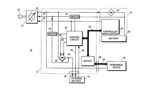
FIG. 1 is a block diagram of a battery charging system in accordance
with the instant invention.
Detailed Description of the Pl~L~ d Embodiment
While the specification concludes with claims defining the features
of the invention that are regarded as novel, it is believed that the
invention will be better understood from a consideration of the following
15 description in conjunction with the drawing figures, in which like
reference numerals are carried forward.
Referring now to FIG. 1, which illustrates a block diagram of a
battery charging system 10 in accordance with the instant invention, there
is shown generally a charger 12 and various system components including
20 power supply 14, electrical device 16, external battery 18, and peripheral
device 20. It should be noted that all components shown are referenced to
a common voltage potential, and as such, ground connections are not
shown for the sake of clarity. It should be assumed, therefore, that each
component has a ground potential that is connected to the power supply
25 reference potential through the charger.
The charger 12 is the central part of the system while the other
components are electrically interconnected to the charger 12, and may be
electrically interconnected to each other through the charger 12. This is
accomplished by providing features on the charger for mechanically
30 receiving the various components, and typically a plurality of electrical
contacts disposed in the ports to mate with corresponding electrical
contacts on the various components. Through these contacts both power
and signals may be transmitted between the components. There exist
numerous means by which elec~rical devices may be so interconnected.
The power supply 14 is connected to an AC power source 22, and
provides a regulated DC voltage level at output 24. Input 26 receives a
feedback voltage level from the other components, as is described
CA 02227624 1998-01-21
W O 97/05668 PCT~US96/11992
hereinbelow, and adjusts the output voltage level at the output 24 to be at a
presPlecte~l dirferenlial above the feedback voltage level. All of the system
components are powered by the output voltage of the power supply by
regulating the output voltage level. For example, the charger would
typically include a 5 volt or a 3.3 volt regulator to power it's internal circuit
components. In the present invention, the feedback voltage level is the
voltage of a battery being charged by the system. This allows the use of a
linear regulator to provide battery charging control because the output
voltage level of the charger can be maintained at a minimum level above
the saturation voltage of the pass transistor used for linear regulation, and
thus considerably reduces the heat generation associated with linear
regulators. More specifically, by minimizing the overhead voltage, the
power dissipated by the linear regulator is reduced to it's lowest level,
making the linear regulator nearly as efficient as a switched mode type. As
such, the ~refe.led voltage differential is about 1.4 volts above the feedback
voltage level. By significantly reducing heat generation, the linear
regulator can be placed in a very small electrical device, such as a cellular
telephone, thereby enabling the device to charge a battery inaccessible by
the charger, and eliminates the need for charger contacts on the battery.
Accordingly, electrical device 16 comprises a rechargeable internal
battery 30, a charging circuit 32, and a controller 34, and a means for
electrically interconnecting the electrical device 16 with the charger 12 is
provided by the charger 12. The internal battery 30 may be removable for
charging separately from the electrical device 16. The output 24 of the
power supply is coupled to the device's charge circuit 32 through the
charger 12. The charging circuit in turn feeds a regulated current level to
the internal battery to recharge the battery. The charge circuit 32 is
responsive of the device's controller 34, which determines when to stop
charging the battery, and may control the charging circuit 32 such that the
charging circuit provides the correct current output level for the particular
battery being recharged. The voltage of the battery is fed back to the power
supply 14 through the charger 12 to the input of the power supply as the
feedback voltage level so that only the minimum voltage necessary is
' provided by the power supply.
In addition to controlling the internal charge circuit 32, controller 34
J is connected to a communication bus 36, such as RS-232, 3-wire, or small
computer systems interface (SCSI), for communicating with other system
CA 02227624 1998-01-21
W 097/05668 PCT~US96/11992
components. A buffer 37 is provided in the charger 12 for latching data
during bus communications, as is common in the art. In particular, a
peripheral device 20 connected at the peripheral port 38 of the charger 12
may be communicated with. The peripheral port 38 is a means for !i
electrically interconnecting the peripheral device with the charger.
Examples of such peripheral devices include personal computers and J
wireless fax modems. Both control and data information may be
transmitted over the bus 36. Several peripheral devices may be connected
in parallel to the bus, each with a unique address.
Additionally, the buffer may be used to provide the proper shift of
voltage in the communications protocol. Since there is a trend towards
lower voltage levels in digital systems, such as from 5 volts to 3.3 volts, it is
preferable that the charger be able to communicate with other devices
regardless of the digital voltage level. For example, a cellular telephone
having a set of telephone numbers may be a 3 volt system. The user
wishing to store the phone numbers in a computer would insert the
telephone in the charger, and connect the computer, via an appropriate
cable, to the peripheral port of the charger. Since the computer is more
likely to operate at higher voltage levels, the buffer ensures the proper
level shift in both directions between the communicating devices.
To maximize the usefulness of the system 10, it is preferable for the
charger 12 to be able to recharge at least one auxiliary or external battery 18.This is accomplished by providing an external battery port for mechanically
receiving and electrically interconnecting the charger 12 with the external
battery 18. To accomplish charging of the external battery 18, the charger 12
requires a current regulator 40, a control circuit 42, and at least 2 switches 44
and 46. The control circuit 42 preferably includes a microprocessor, such as
the MC68HC05B6 manufactured by Motorola Inc., and an EPROM, or other
non-volatile storage, for storing instruction sets and allowing for changes
in the product once in the hands of the consumer. The current regulator
40 may be either of the linear type or the switched mode type. Both types
are well known in the art, and the advantages and disadvantage of each
must be weighed by the designer of the system 10 in determining which is
more suitable for the particular application. The current regulator is
controlled by the control circuit 42 with regard to current regulation level
by at least one line 48. This line 48 may be either an on/off type control, or
a reference level provided by the control circuit 42. Preferably two lines are
CA 02227624 1998-01-21
W O 97/05668 PCTAUS96/11992
used, line 48 for on/off control and lin~ 50 for providing the reference
level. The regulator output 52 is fed to the external battery 18, and the
voltage subsequently produced is fed back to the power supply input 26 as a
feedback voltage level through switch 44.
Switches 44 and 46 are necessary when the system is capable of
charging more than one battery, and are preferably transistor switches such
as MOSFETs. Since the power supply's output voltage level is determined
by the feedback voltage provided by the particular battery being charged,
whether it is an internal battery 30 or an external battery 18. As such, only
the battery voltage of the particular battery being charged should be fed to
the input 26 of the power supply, to the exclusion of any other battery
voltage. Accordingly, control circuit 42 monitors the system to determine
which battery is being charged and closes the appropriate switch. Either
switch 44 or switch 46 is closed and the other is opened. Should the
charger 12 be engaged in charging an external battery at the time when an
electrical device 16 is first connected to the system, and the internal battery
30 of the device 16 requires charging, the device 16 communicates this to
the control circuit 42 by bus 36, or a separate line such as information line
28. The control circuit then switches switch 44 off, and switch 46 on,
thereby allowing the device 16 to charge it's internal battery 30. When the
device 16 is finished, the device notifies the control circuit by bus 36, and
the charger resumes charging the external battery. The external battery 18
preferably provides a temperature indication signal 54 so that the charger
12 can monitor the temperature of the battery 18. Additionally, the battery
18 may provide a data signal 56 to indicate parameters such as capacity of
the battery and the chemistry of the battery.
In addition to the input and output provided by the power supply
14, it may additionally provide an information line 28. This line allows
the system components to query the power supply 14 to determine, among
other parameters, the output capacity, i.e. the power supply's maximum
current output level. This information helps the system components
decide how to distribute power. For example, if a device is recharging a
battery at a current level x, and the device needs to perform some other
~l operation which requires a current level y, and where x+y exceeds the
35 maximum current output level of the power supply, the device would
shut off the charging circuit momentarily while performing the other
operation. In this way power supplies can be kept small since they won't
CA 02227624 1998-01-21
W O 97/05668 PCT~US96/11992
have to provide all system components with maximum power
simultaneously at any given moment. This results in a form of power
rationing.
The present invention thus provides a system which allows portable
5 electrical devices to be connected to peripheral devices while charging one
or more batteries. It allows the reduction of the number of contacts
provided by the batteries since the electrical device itself carries it's own
charging control circuitry, thereby eliminating the need for separate
charger mating contacts. By allowing communication between the
10 components, a form of power rationing can be implemented, thus
allowing the power supply to be smaller than is typically required.
While the preferred embodiments of the invention have been
illustrated and described, it will be clear that the invention is not so limited.
Numerous modifications, changes, variations, substitutions and equivalents
15 will occur to those skilled in the art without departing from the spirit and
scope of the present invention as defined by the appended claims.
What is clairned is: