Note: Descriptions are shown in the official language in which they were submitted.
CA 02227778 1998-01-23
W O 97t05324 PCTAUS96/12903
METHOD AND APPARATUS FOR BLEACHING HIGH CONSISTENCY
PULP WITH A GASEOUS BLEACHING REAGENT
~ CROSS-REFERENCES
The subject application is a continuation-in-part of
U.S. Provisional Patent Application having Serial No.
60/001,446 filed on July 26, 1995, entitled: "Ozone
Bleaching System Combining Pin Fluffer And Bed Reactor",
and is related to the following co-pending and commonly
assigned U.S. Patent Applications which are expressly
incorporated by reference herein: Serial No. 08/125,053
filed on September 21, 1993, entitled "Apparatus For
Fluffing High Consistency Wood Pulp"; Serial No.
08/335,282 filed on November 7, 1994, entitled "Apparatus
For Fluffing And Contacting High Consistency Wood Pulp
With a Gaseous Bleaching Reagent"; and Serial No.
08/398,317 filed on March 3, 1995, entitled "Variable
Angle Powered Cyclone".
BACKGROUND OF THE INVENTION
1.0 Field of the Invention
The present invention relates generally to the
bleaching of lignocellulosic materials for use in the pulp
and paper industry, and more particularly to a method and
apparatus for bleaching high consistency pulp with a
gaseous bleaching reagent such as ozone.
SlJBSTlTUTE SY.E~T (RULE 26)
CA 02227778 1998-01-23
WO 97/05324 PCTAUS96/12903
2.0 Related Art
The use of gaseous reagents, including chlorine
dioxide and ozone, ~or the bleaching of lignocellulosic
materials including wood pulp is well known in the art. It
is further known, particularly with respect to the
bleaching of high consistency wood pulp, that mechanical
mixing of the pulp in the presence of the bleaching
reagent is required to enhance the rate of reaction
between the bleaching reagent and the pulp and to achieve
uniformity of the resultant bleached pulp.
As known in the art, wood pulp is obtained from the
digestion of wood chips or from repulping of recycled
paper or from other sources and is commonly processed in
pulp and paper mills in slurry form in water. As used
herein, the term "consistency" is used to express the
measured ratio of dry pulp fibers to water, or more
specifically, the weight of dry pulp fiber in a given
weight of pulp slurry or "pulp stock" as a percentage.
Various definitions are used, such as air-dry consistency
(a.d.%), or oven-dry consistency (o.d.%), or moisture-free
consistency (m.f.%). The laboratory techniques for
measuring these values can be found in references well
known in the art, such as the TAPPI Standards Manual.
Terms widely used to describe ranges of stock consistency
useful in pulp and paper plants follow:
Low Consistency - below about 4-6% o.d. Medium
Consistency - about 9-18% o.d.
High Consistency - above about 18-20% o.d., but
more commonly above about 25% o.d.
SUBSTITUTE SHEET (RULE 26)
CA 02227778 1998-01-23
WO 97/05324 PCTnJS96/12903
The primary characteristic of pulp slurries which changes
with consistency is the fluidity. Low consistency slurries
flow like water and can easily be pumped through pipelines
using normal centrifugal pumps. In contrast, medium
consistency pulp slurries have a paste-like character, do
not flow by gravity, and can only be pumped in pipelines
by using specially designed pumps. Also in contrast, wood
pulp in the high consistency range does not have a
slurry-like character, but is better described as a damp,
fibrous, solid mass. Upon superficial examination, high
consistency wood pulp appears to be and act like a dry
solid. Accordingly, high consistency wood pulp generally
cannot be pumped through any great distance in pipelines
because the pipe wall friction is very high, resulting in
uneconomic pumping horsepower requirements. However, this
characteristic is used to advantage in some prior art
bleaching systems which feed high consistency pulp to a
gas filled vessel through a short length of pipe in which
the pulp forms a plug sufficiently impermeable to prevent
loss of reaction gas in the reverse direction. High
consistency wood pulp has an additional characteristic
which is that it can be fluffed, in the same way that dry
fibrous solids such as cotton or feathers can be fluffed,
to give a light and porous mass, the inner fibers of which
are accessible to a chemical reagent in gaseous form.
Fluffed, high consistency pulp can be blown with air or
bleaching gases through pipelines provided sufficient
velocity is used to prevent the wet fibers from settling
out of the gas suspension. It is understood in the art
SUBSTITUTE SH~ET (RULE 26)
CA 02227778 1998-01-23
WO 97/05324 PCT~US96/12903
-- 4 --
that the agitation of pulp, for the aforementioned
reasons, requires the expenditure of energy and increases
the pulp processing costs both with regard to the initial
capital investment and with regard to equipment
maintenance costs in proportion to the degree of
mechanical effort expended.
One known system for bleaching high consistency pulp
with chlorine dioxide includes a device commonly referred
to as a fluffer/blower. The pulp is mechanically fluffed
within the fluffer/blower in the presence of the chlorine
dioxide and the associated carrier gas so as to form a
gas-suspended mixture for transport and initiation of the
bleaching reaction. The gas-suspended pulp is then
transported through a conduit to the top of a reactor
tower, of the porous bed type. A relatively high transport
velocity is required within the conduit and accordingly
the flow within the conduit is turbulent in nature, which
maintains the pulp in a gas-suspended mixture and
continues the reaction of the pulp with the chlorine
dioxide. The pulp then enters an upper portion, commonly
referred to as a cyclone, of the porous-bed reactor tower
in a tangential manner, causing the gas-suspended pulp to
swirl around the inner wall of the reactor tower cyclone,
so as to further react the pulp with the chlorine dioxide
and at the same time to separate the pulp from an excess
of gas required for transport, with the excess gas being
returned to the fluffer/blower. The pulp then drops onto a
porous bed of fluffed pulp, within the reactor tower,
which continuously moves downward through the reactor
SUBSTITUTE SHEET (RULE 26)
CA 02227778 l998-0l-23
W O 97/05324 PCT~US96/12903
tower toward an expanded section which acts as a gas
separation chamber. The total residence time of the pulp
within the fluffer/blower, the transport conduit and the
reactor tower cyclone (prior to the pulp dropping onto the
porous bed of fluffed pulp) is approximately 5 seconds.
Notwithstanding the relatively short combined pulp
residence time a substantial portion of the chlorine
dioxide, comprising about 60% to about 80% of a given
chlorine dioxide dose, is consumed within the
fluffer/blower, transport conduit and reactor tower
cyclone due to the very fast reaction rate characteristics
of chlorine dioxide. The chlorine dioxide and carrier gas
flow downward through the porous bed at a substantially
higher velocity than that at which the pulp bed moves
downward through the reactor, so as to substantially
complete the reaction of the chlorine dioxide with the
pulp. The carrier gas then flows into a gas separation
chamber within the reactor and is subsequentiy recycled.
Although bleaching systems of this type have proven
somewhat effective for the bleaching of high consistency
pulp with chlorine dioxide, they are subject to the
following limitations. The pulp residence time within the
fluffer/blower is substantially fixed and is controlled by
the fluffer speed required to achieve shredding and
fluffing of the pulp. The pulp residence time within the
transport conduit interconnecting the fluffer/blower and
the bed reactor is also substantially fixed (without an
impractical increase in conduit length) due to the
transport velocity required within the conduit.
Accordingly, such systems provide limited flexibility with
SUBSTITUTE SHEET (RULE 26~
CA 02227778 1998-01-23
W O 97/05324 PCT~US96/12903
-- 6 --
regard to the ability to vary pulp residence time, while
the pulp is agitated and maintained suspended in the
gaseous bleaching reagent.
Recently, there have been many efforts to utilize
ozone as the bleaching reagent for high consistency wood
pulp, and other lignocellulosic materials, to avoid the
use of chlorine ~and the attendant environmental problems)
in such bleaching processes. Although ozone may initially
appear to be an ideal material for bleaching
lignocellulosic materials, the exceptional oxidative
properties of ozone and its relatively high cost have
limited the development of satisfactory devices and
processes for ozone bleaching of lignocellulosic
materials. For instance, the inventors have determined
that the previously described system for bleaching high
consistency wood pulp with chlorine dioxide does not
provide optimum results when bleaching with ozone, due to
the aforementioned inflexibility regarding pulp residence
time with the pulp in an agitated, gas-suspended state.
Also, a large amount of energy is required, in addition to
that expended in fluffing the pulp, to transport the gas
suspension of pulp from the fluffer/blower to the top of
the bed reactor~
The foregoing illustrates limitations known to exist
in present wood pulp bleaching operations. Thus, it is
apparent that it would be advantageous to provide an
alternative directed to overcoming one or more of the
limitations set forth above. Accordingly, a suitable
SUBSTITUTE SI~EET (RULE 26)
CA 02227778 1998-01-23
W O 97/0~324 PCTAJS96/12903
alternative is provided including features more fully
disclosed hereinafter.
SUMMARY OF THE INVENTION
In one aspect of the present invention, this is
accomplished by providing a method for bleaching high
consistency pulp with a gaseous bleaching reagent
comprising the steps of:
supplying a high consistency pulp to a first,
upstream vessel;
shredding the pulp within the upstream vessel in the
presence of a contacting gas including the gaseous
bleaching reagent, a carrier gas, and reaction by-product
gases so as to suspend the pulp in the contacting gas and
to initiate reaction of the gaseous bleaching reagent with
the pulp;
fluffing the shredded pulp within the upstream vessel
in the presence of the contacting gas so as to maintain
the pulp in suspension in the contacting gas and to
further react the gaseous bleaching reagent with the pulp,
wherein said step of fluffing includes the steps of
creating a rotating annulus of fluidized particles of
the shredded pulp within the upstream vessel,
combing the rotating annulus of fluidized particles
of the shredded pulp so as to further reduce the size of
the shredded pulp particles and to fluff the pulp
particles;
retaining the high consistency pulp within the
upstream vessel for a predetermined time which is
SUBSTITUTE SH'ET (RULE 26)
CA 02227778 1998-01-23
W O 97/05324 PCT~US96/12903
sufficient to consume about 75% to about 90% of a selected
dose of the gaseous bleaching reagent which is required to
delignify the high consistency pulp from an initial Kappa
number to an intermediate Kappa number; and
discharging the fluffed pulp and the contacting gas
from the upstream vessel to a second, downstream vessel in
which the reaction of the selected dose of the gaseous
bleaching reagent with the pulp is substantially completed
so as to further delignify the high consistency pulp from
the intermediate Kappa number to a final Kappa number.
According to a second aspect of the present
invention, this is accomplished by providing a system for
bleaching high consistency pulp with a gaseous bleaching
reagent, with the system comprising:
a substantially vertical pin/foil contactor having a
gas inlet, a gas outlet, a pulp inlet, and a pulp outlet;
means for supplying high consistency pulp to said
pulp inlet of said contactor;
means for supplying fresh bleaching gas to said gas
inlet of said contactor; and
a porous bed reactor having a gas inlet, a gas
outlet, a pulp inlet, and a pulp outlet, wherein said gas
inlet of said reactor is in fluid c~m~lln;cation with said
gas outlet of said contactor and wherein said pulp inlet
of said reactor communicates with said pulp outlet of said
contactor; and
wherein said contactor further includes means for
shredding the high consistency pulp supplied to said pulp
SUBSTITUTE Si~ET (RULE 26)
CA 02227778 1998-01-23
W O 97/05324 PCT~US96/12903
inlet of said contactor and means for ~lu~fing the
shredded pulp.
BRIEF DESCRIPTION OF THE DRAWINGS
The foregoing and other aspects of the present
invention will become more apparent from the subsequent
Detailed Description of the invention when considered in
conjunction with the accompanying drawing figures,
wherein:
Fig. 1 schematically illustrates a prior system for
bleaching lignocellulosic materials, such as high
consistency wood pulp, with a gaseous bleaching reagent;
Fig. 2 graphically illustrates the kinetics of the
reaction of ozone with high consistency high consistency
wood pulp, for various ozone in carrier gas concentrations
in a continuous co-current plug flow reactor;
Fig. 3 schematically illustrates a system for
bleaching lignocellulosic materials, such as high
consistency wood pulp, with a gaseous bleaching reagent,
according to the present invention;
Fig. 4 is an elevational view, partly in cutaway
view, further illustrating a portion of the pulp bleaching
system shown in Fig. 3;
SUBSTITUTE SHEET (RULE 26)
CA 02227778 1998-01-23
W O 97/05324 PCTAJS96/12903
-- 10 _
Fig. 5 is a partial, perspective view further
illustrating a portion of the pulp bleaching system shown
in Fig. 4;
Fig. 6 illustrates the ozone bleaching kinetics
within the apparatus of the present invention and compares
the effects of co-current and counter-current flow of
ozone in an upstream, or first stage bleaching vessel,
followed by concurrent flow of ozone in a downstream, or
second stage bleaching vessel.
DETAILED DESCRIPTION
Referring now to the drawings, Fig. 1 schematically
illustrates a prior art system 10 for bleaching
lignocellulosic materials, such as high consistency wood
pulp, with a gaseous bleaching reagent comprising chlorine
dioxide. Wood pulp 12 enters a press feed tank 14 where it
is diluted with pressate to form a pulp slurry having a
consistency of about 4%. Sulfuric acid is added to the
pulp slurry within tank 14 so as to reduce the pH of the
pulp slurry to about 2-3. The pulp slurry is then
transported, via conduits 16 and 18, to a twin roll
dewatering press, such as an IMPCO Vari-Nip~ twin roll
press made by the Beloit Corporation. The pulp is then
shredded in a double flight conveyor 22 and transported
externally of press 20 where it drops into a thick stock
pump 24 such as an IMPCO Clove-Rotor~ thick stock pump
made by the Beloit Corporation. The high consistency pulp
discharging from pump 24 is supplied to a fluffer/blower
SUBSTITUTE StlEET (RULE 26)
CA 02227778 1998-01-23
W O 97/05324 PCT~US96/12903
1 1
26 via conduit 28. The fluffer/blower 26 includes means
for disintegrating, or shredding the high consistency pulp
into relatively small flocs and also fluffs the pulp in
the presence of a bleaching gas including a gaseous
bleaching reagent, comprising chlorine dioxide, and a
carrier gas, so as to suspend the fluffed pulp in the
bleaching gas. A flow of bleaching gas is supplied to the
fluffer/blower 26 from an upper portion 30 of a
substantially vertically oriented porous bed reactor 32
via conduit 34. Fresh bleaching gas i6 supplied to conduit
34 from a source 36 of chlorine dioxide via conduit 38.
The reaction of the chlorine dioxide with the high
consistency pulp is initiated in the fluffer/blower 26 and
continues in the conduit 40, used to transport the
gas-suspended pulp to reactor 32, and in the upper portion
30 of the reactor 32. The flow through conduit 40 is
turbulent in nature which agitates the pulp and maintains
the pulp in a gas-suspended mixture with the chlorine
dioxide and the associated carrier gas. The gas-suspended
pulp enters the upper portion 30 of reactor 32 from
conduit 40 in a tangential manner 80 that the
gas-suspended pulp swirls around the inner wall of the
upper portion 30 of reactor 32 in a cyclonic fashion.
Hence, portion 30 may be referred to in the art as a
cyclone. The pulp then drops onto a porous bed of fluffed
pulp (not shown) within reactor 32, and the pulp bed moves
continuously downward through reactor 32. Since the flow
of gas required for pulp transport through conduit 40 is
usually much larger than the fresh bleaching gas entering
from conduit 38, the excess gas is separated from the pulp
SUBSTITUTE SHEET (RULE 26)
CA 02227778 1998-01-23
W097/05324 PCT~US96/12903
in cyclone 30 and returned to the fluffer/blower 26
through conduit 34. The inventors have determined that the
combined pulp residence time within ~he fluffer/blower 26,
conduit 40 and the upper portion 30 of reactor 32 (prior
to the pulp falling on the fluffed bed) is approximately 5
seconds. Due to the agitation of the pulp, and
consequently the intimate contact of the pulp with the
chlorine dioxide, within the fluffer/blower 26, conduit 40
and the upper portion 30 of reactor 32, about 60% to about
80% of a given dose of the chlorine dioxide is consumed
within fluffer/blower 26, conduit 40 and the upper portion
30 of reactor 32. This relatively large percentage of
chlorine dioxide is consumed, notwithstanding the
relatively short pulp residence time, since the reaction
rate of chlorine dioxide with pulp is very fast.
Substantially all of the remaining chlorine dioxide is
consumed as the chlorine dioxide passes through the
fluffed pulp bed, at a substantially higher velocity than
that at which the bed moves downward through reactor 32.
The fluffed bed of pulp may reside in reactor 32 for a
relatively long time, on the order of several minutes, to
substantially complete the reaction of the chlorine
dioxide with the pulp due to the characteristic "tail" of
the chlorine dioxide bleaching kinetics curve, which is
known in the art. A dilution liquor, indicated by flow
arrow 41, may be added to a lower portion of reactor 32 so
as to achieve a desired consistency of the pulp for
further processing. The manner in which the pulp
discharges from reactor 32 depends on the requirements of
the subsequent bleaching stage of the associated
SUBSTITUTE SHEET (RULE 26)
CA 02227778 1998-01-23
W O 97/0532~ PCT~US96/12903
- - 13 _
processing plant. In the system 10 shown in Fig. 1, the
pulp is extracted from reactor 32 using a dilution scraper
42, with the diluted pulp then being transferred to a
receiving tank 44 via conduit 46. The pulp may then
discharge tank 44, after appropriate treatment, for
further processing as shown by flow arrow 48. Any
remaining chlorine dioxide which has not been consumed, as
well as the associated carrier gas, discharges into an
annular gas separation chamber 47 of reactor 32 and
discharges from chamber 47 for further processing, as
shown by flow arrow 49.
Although system 10 has been used with success in
certain applications, such as the aforementioned bleaching
of high consistency pulp with chlorine dioxide, it is
subject to the following limitations. The pulp residence
time within the fluffer/blower 26 is substantially fixed
and is controlled by the rotational speed which is
required to achieve disintegration and fluffing of the
high consistency pulp supplied to fluffer/blower 26. The
pulp residence time within transport conduit 40 is also
substantially fixed (without an impractical increase in
conduit length) due to the relatively high transport
velocity required within conduit 40. Accordingly, system
10 provides very limited flexibility with regard to
changing the pulp residence time prior to contacting the
fluffed bed of pulp within reactor 32.
The inventors have experimentally determined the
bleaching kinetics of ozone, or the rate of reaction of
SU~STITUTE S~EET (RULE 26)
CA 02227778 1998-01-23
W O 97/05324 PCTAUS96/12903
_ 14 -
ozone with high consistency pulp, which is shown in Fig. 2
for a variety of concentrations of ozone in an oxygen
carrier gas ranging from 6% ozone concentration to 14%
ozone concentration. This range of ozone concentrations
represents those which are presently commercially
available and economically feasible in the required
quantities for the commercial bleaching of high
consistency wood pulp, with 6% ozone concentration
presently being particularly attractive from a cost
standpoint. However, it is noted that ozone generator
technology is rapidly changing and that accordingly, other
concentrations of ozone may become economically viable in
the future. The data presented in Fig. 2 was
experimentally determined as follows. A laboratory scale
batch apparatus was built to measure ozone consumption in
a mechanically agitated bleaching contactor at residence
times as short as 2 seconds. Ozone delignifications were
run at various gas concentrations and residence times
using a Canadian softwood Kraft pulp which had been oxygen
delignified in the laboratory to 10.5 Kappa number. The
contactor included a 5 liter capacity reaction chamber,
suitable for accepting a charge of approximately 100 g
o.d. fluffed pulp. The Kraft-oxygen pulp samples were well
washed, acidified to pH 2 with sulfuric acid at low
consistency and then dewatered in a press to 40% o.d.
Portions of the pulp cake were weighed out and then
fluffed immediately prior to each run in the contactor.
The dewatered, fluffed pulp was manually charged into the
reaction chamber which was then closed. Air was evacuated
with a vacuum pump and a high-speed (1750 rpm) rotor
SUBSTITUTE SI~E~T (RULE 26)
CA 02227778 1998-01-23
WO 97/05324 PCT~US96/12903
fitted with pointed pins and rotatably mounted within the
reaction chamber, was started. Next, a quick opening valve
allowed the ozone/oxygen gas to rush in from an
accumulator. This was followed by a reaction period at
constant pressure and the rotor kept the fluffed pulp
rotating in a layer against the inner wall of the reaction
chamber and imparted a combing action to the fiber flocs.
Next, a fast nitrogen purge expelled residual gas to a
second accumulator for titration. The combined inrush and
reaction period was varied from about 2 seconds to about
60 seconds in successive runs. The ozone gas charge was
calculated from the initial and final pressures and the
known volume of the reaction chamber, and its
concentration by titrating a volumetric sample from the
feed accumulator. The total residual ozone was obtained
from titration of samples from the purged gas accumulator.
The consumed ozone was the difference of these two
calculations.
The inventors have determined that for optimum
bleaching results using ozone, that it is desirable to
consume about 75% to about 90%, and more preferably about
80% to about 90%, of the ozone dose while the high
consistency pulp is being agitated and suspended within
the ozone, which contrasts with the 60% to 80% of chlorine
dioxide consumed in system 10 during the period of time
that the pulp is suspended in the chlorine dioxide within
fluffer/blower 26, transport conduit 40 and the cyclone,
or upper portion 30 of the porous bed reactor 32. As shown
in Fig. 2, the time required to achieve the more preferred
SUBSTITUTE S~rET (RULE 26)
CA 02227778 1998-01-23
W O 97/05324 PCT~US96/12903
- - 16 -
range of about 80~ to about 90% ozone consumption, for a
given ozone dose, varies from about 5 seconds to about 20
seconds, depending upon the concentration of the ozone
used. Also as shown in Fig. 2, if the concentration of the
ozone is 6%, which is presently economically attractive,
the time required to achieve 80% to 90% ozone consumption
varies from about 10 second to about 20 seconds.
Accordingly, based on the combined pulp residence time of
about 5 seconds within fluffer/blower 26, transport
conduit 40 and the cyclone 30 of reactor 32, in
combination with the aforementioned limited flexibility of
system 10 to vary the pulp residence time within the
fluffer/blower 26 and transport conduit 40, the inventors
have determined that system 10 is not adequate for
producing optimum results when bleaching high consistency
wood pulp with ozone.
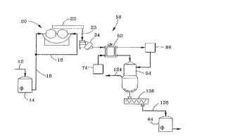
Referring now to Figs. 3, 4, and 5 a system 50 for
bleaching lignocellulosic materials, such as high
consistency wood pulp, with a gaseous bleaching reagent,
is illustrated according to a preferred embodiment of the
present invention. System 50 is shown in schematic form in
Fig. 3, and specific details of construction of portions
of system 50 are further illustrated in Figs. 4 and 5. As
described herein, the apparatus of the present invention
depicted in the illustrative embodiment shown in Figs.
3-5, will be described in conjunction with a method for
bleaching high consistency wood pulp utilizing ozone as
the gaseous bleaching reagent, according to the method of
the present invention. The apparatus and method of the
SUE3STITUTE SHEET (RULE 26)
CA 02227778 l998-0l-23
W 097/05324 PCTAUS96/12903
17 _
present invention are not intended to be utilized for the
bleaching of either medium consistency or low consistency
wood pulp. As known in the art, due to the manner in which
ozone is generated, ozone is typically available at a
relatively low concentration within a carrier gas, such as
oxygen or air. Typically, the concentration of ozone which
is presently commercially available at attractive costs,
ranges from about 6% to about 10% by weight when using
oxygen as the carrier gas. As used herein, the term
"contacting gas" will refer to the mixture of ozone in an
oxygen carrier gas, as well as other gases and vapors,
such as by-product gases of reaction, which are present at
equilibrium conditions. The term "fresh bleaching gas"
will be used to denote a mixture of ozone in an oxygen
carrier gas supplied from a conventional source, such as a
dryer/cleaner and ozone generator, which has not been
reacted with the pulp and accordingly does not include
reaction by-product gases.
The operation of system 50 is the same as that of
system 10 up to the point where the high consistency pulp
discharges from the Clove-Rotor~ pump 24. As seen by
comparing Figs. 1 and 3, system 50 does not include the
fluffer/blower 26, or the transport conduits 34 and 40 of
system 10. Instead, after the high consistency pulp is
discharged from the pump 24 in system 50, the high
consistency pulp is bleached with ozone within a first,
upstream vessel 52 and is then bleached within a second,
downstream vessel 54, as subsequently described.
S~JBST~TUTE SllEET (RULE 26)
CA 02227778 1998-01-23
W O 97/05324 PCT~US96/12903
- 18 -
Referring again to Figs. 3-5, a high consistency wood
pulp 23 is supplied from the dewatering press 20 to the
Clove-Rotor~ pump 24 which operates in a manner well known
in the art. Pump 24 forces the high consistency pulp 23
through a pipe 58 and into a pulp inlet 56 of vessel 52.
Due to the frictional resistance of the pulp 23 within
pipe 58, an impervious moving pulp plug is formed within
conduit 58 which is effective for preventing the back-flow
of contacting gas from vessel 52.
Vessel 52 comprises a pin/foil contactor and is
substantially vertically oriented as shown in Fig. 4.
Contactor 52 includes a housing 62 and a shaft 63 which is
rotatably mounted within housing 62. Shaft 63 is rotatably
driven by a motor 66 which may comprise a variable-speed
motor. A rotor drum 64 is attached to shaft 63 for
rotation with shaft 63. The housing 62 includes an upper
portion 68, comprising a gas separation chamber, and a
lower portion 70 with means contained therein for
shredding the high consistency pulp supplied through pulp
inlet 56 and for fluffing the pulp within the presence of
a contacting gas including ozone, an oxygen carrier gas
and by-product of reaction gases. Fresh bleaching gas,
comprising ozone in an oxygen carrier gas, is supplied to
a gas inlet 72 of contactor 52 from a source 74 of fresh
bleaching gas via a conduit 76. The source 74 of fresh
bleaching gas may comprise an ozone generator and a
dryer/cleaner. A helically disposed screw flight 78 is
attached to drum 64 for rotation therewith and is disposed
below the gas separation chamber 68 and extends through an
SIJBSTIT~JTE SHEET ~'RULE 26)
CA 02227778 1998-01-23
W O 97/~5324 PCTAJS96/12903
upper portion of the lower portion 70 of housing 62. The
screw flight 78 is substantially aligned with the pulp
inlet 56 of contactor 52, and includes a plurality of
teethlike surfaces disposed along the outer periphery of
screw flight 78. Accordingly, screw flight 78 is effective
for shredding the high consistency pulp entering through
inlet 56 into relatively small particles. Screw flight 78
is also effective for imparting a circumferential velocity
to the pulp particles within housing 62. Contactor 52
further includes a plurality of pins 80 which are attached
to drum 64 and extend radially outwardly from drum 64 to a
location proximate an inner wall 71 (shown in Fig. 5) of
the lower portion 70 of housing 62. The pins rotate with
shaft 63 and drum 64 about an axially extending,
substantially vertical centerline axis 82 of contactor 52.
Pins 80 are disposed in a plurality of axially spaced
rows, with each axial row including a plurality of
circumferentially spaced pins 80. The rotating action of
the screw flight, or shredder 78 as well as the
centrifugal force exerted on the shredded pulp by the
rotating action of pins 80, forces the pulp radially
outward against the inner wall 71 of the lower portion 70
of housing 62. A rotating annulus of fluidized particles
of the shredded pulp is created in an annular space 84
which exists between the inner wall 71 of lower portion 70
of housing 62 and the rotor drum 64. The rotating annulus
of pulp is rotatable about the centerline axis 82 of
contactor 52, and has a tangential velocity which is less
than that of the tips of pins 80. As shaft 63 and drum 64
are rotated, the tips of pins 80 comb through the annulus
SUBSTITUTE SHEET (RULE 26)
CA 02227778 1998-01-23
W O 97/05324 PCT~US96/12903
- - 20 -
of pulp, so as to further reduce the size of the shredded
pulp particles and to fluff the pulp particles in the
presence of the contacting gas within housing 62.
Accordingly, the fluffed pulp is maintained in a fluidized
state within the contacting gas as it swirls around the
inner wall of the lower portion 70 of housing 62 and moves
downward through annulus 84. The ozone and oxygen carrier
gas which enters housing 62 through gas inlet 72, flows
upward through housing 62 in a countercurrent relationship
with the pulp, which is moving downward through housing
62. The countercurrent flow of the contacting gas within
housing 62 is induced by a blower 86 which is in fluid
communication with a gas outlet 88 of contactor 52 via
conduit 90. The gas outlet 88 is in fluid communication
with the gas separation chamber 68 of contactor 52. The
contacting gas discharging from contactor 52 to blower 86
is then supplied to a gas inlet 92 of the downstream
vessel 54 via conduit 94.
The substantially vertical pin/foil contactor 52
further includes a plurality of circumferentially spaced
columns of guide foils 96, with one of the columns being
partially shown in perspective view in Fig. 5. The number
of columns of guide foils 96 may vary with application.
Each column of guide foils 96 includes a plurality of
axially aligned and axially spaced guide foils 96, as
shown in Fig. 5. The presence of guide foils 96 permits
the substantially vertical pin/foil contactor 52 to bè
cylindrical in design, rather than conical, for instance.
More specifically, guide foils 96 allow the desired pulp
SUBSTITUTE SHEET (RULE 26)
CA 02227778 1998-01-23
W O 97/05324 PCT~US96/12903
- 21 -
residence time within contactor 52 to be achieved. Without
guide foils 96, the pulp would precipitously fall through
contactor 52 in a very short period of time, preventing
the desired bleaching of the pulp within contactor 52. The
guide foils 96 of each column may be attached to a mount
plate 98, which in turn is attached to the inner wall 71
of the lower portion 70 of housing 62. Each guide foil 96
includes a first, substantially flat portion 100 and a
second, arcuate portion 102 which is curved upward
relative to the flat portion 100 and functions in a manner
similar to that of an airfoil by imparting lift to the
fluffed pulp as it slides past each guide foil 96. As
shown in Fig. 4, guide foils 96 are interleaved with pins
80 so that pins 80 and guide foils 96 are disposed in a
vertically alternating arrangement. The vertically
alternating arrangement of pins 80 and foils 96 extend
substantially throughout the axial length of the lower
portion 70 of housing 62. Each guide foil 96 further
includes a leading edge 104, formed on the substantially
flat portion 100. The leading edge 104 forms a shallow,
radially inwardly diverging angle relative to a radial
line, which serves to retard the development of pulp plugs
and to promote the shedding of fiber build-up that would
otherwise develop on a square leading edge. Additionally,
the geometry of foils 96 i8 such that foils 96 exert a
minimal drag on the rotating annulus of fluidized pulp
particles so as not to retard the circumferential velocity
of the rotating annulus of fluidized pulp particles.
Furthermore, the projected frontal area of foils 96 is
significantly smaller than that of pins 80 which is
SUBSTITUTE SHEET (RULE 26)
CA 02227778 1998-01-23
W O 97/05324 PCT~US96/12903
important as this relative sizing of foils 96 and pins 80
permits the formation of the rotating annulus of fluidized
pulp particles. In a preferred embodiment, the projected
frontal area of foils 96 is about one-fourth, or less,
than the projected frontal area of pins 80. The projected
frontal area of foils 96 is mlnim; zed consistent with the
structural requirements of foils 96 and with the extent of
the arcuate portion 102 of each foil 96 which is required
to impart the desired lift to the fluffed pulp as it
slides past each guide foil 96. Foils 96 are discussed and
further illustrated (as element 25) in co-pending and
commonly assigned U.S. Patent Application having Serial
No. 08/335,282.
As discussed previously, the inventors have
determined that for purposes of enhanced uniformity of the
bleached pulp, it is desirable to consume about 75% to
about 90%, and more preferably about 80% to about 90%, of
a given ozone dose while the pulp is in an agitated,
gas-suspended mixture, such as that which exists within
contactor 52. Accordingly, the pulp is retained within
contactor 52 for a predetermined time which varies
depending upon the desired percentage of ozone consumption
and the ozone concentration. For instance, in order to
achieve the more preferred range of about 80% to about 90%
of ozone consumption within contactor 52, the pulp
residence time within contactor 52 ranges from about 5
seconds to about 20 seconds for ozone concentrations
ranging from 6% to 14%, due to the ozone bleaching
kinetics shown in Fig. 2 which were experimentally
SUBSTITUTE SHEET (RULE 26)
CA 02227778 1998-01-23
W O 97105324 PCT~US96/12903
determined by the inventors. This pulp residence time
within contactor 52 may be achieved by varying the speed
of motor 66, and the corresponding rotating speed of pins
~ 80, as well as varying the flow rate of the bleaching gas
supplied to inlet 72 of contactor 52 and the design of
guide foils 96. The inventors have determined that the use
of the substantially vertical pin/foil contactor 52
provides excellent results, with respect to uniformity of
pulp bleaching, for the following reason. The intense
agitation of the pulp with pins 80 causes the pulp to be
maintained in suspension in the contacting gas in the form
of a fluidized solid disposed in the annular space 84
between the rotor drum 64 and the inner wall 71 of the
lower portion 70 of housing 62. Accordingly, all of the
pulp is in intimate contact with the ozone bleaching
reagent throughout the entire pulp residence time within
contactor 52.
The pulp particles are discharged from contactor 52
through a tangentially oriented pulp outlet 106 of
contactor 52. The circumferential velocity imparted to the
pulp as it travels downward through housing 62 causes the
pulp particles to be flung tangentially through outlet 106
into an elbow-shaped conduit, or pipe 108 which is
attached at one end to a substantially vertically oriented
pulp inlet 110 of the downstream vessel 54, which
comprises a porous bed reactor. Virtually no contacting
gas discharges from outlet 106 of contactor 52. Instead,
as discussed previously, the contacting gas is separated
from the pulp within gas separation chamber 68 and is then
SUBSTITUTE SHEET (RULE 26)
CA 02227778 1998-01-23
W O 97/05324 PCT~US96/12903
- 24 -
routed to the gas inlet 92 of the porous bed reactor 54
via conduits 90 and 94 and blower 86. The fluffed pulp
entering reactor 52 through inlet 110 drops onto a porous
bed 112 of fluffed pulp, which moves continuously downward
through the porous bed reactor 54. The contacting gas
flows through the porous bed at a substantially higher
velocity than that of the bed, so as to substantially
complete the reaction of the pulp with the ozone. The pulp
residence time within reactor 54 may be varied, by varying
the fill level of the pulp within reactor 54, for
instance, so that about 95% to about 97% of a given ozone
dose is consumed after the contacting gas has passed
through the porous bed. The oxygen carrier gas, and any
remaining ozone which has not been consumed, then
discharges into an annular gas separation chamber 114, as
indicated by flow arrows 116. The gas separation chamber
114 is formed at the interface between the relatively
smaller diameter, generally cylindrical upper portion 118
of reactor 54 and the relatively larger diameter,
generally cylindrical lower portion 120 of reactor 54. The
gas entering the gas separation chamber 114 then
discharges reactor 54 through a gas outlet 122, as shown
by flow arrow 124, with the gas being recycled for further
processing. For instance, the gas discharging from outlet
122 may be supplied to a dryer/cleaner and ozone generator
so that the oxygen carrier gas may be reused. The bleached
pulp 126 at the bottom of reactor 54 then discharges
reactor 54 through a pulp outlet 128 as shown by flow
arrow 130, for further processing. The selection of the
apparatus used to discharge the pulp from reactor 54
SUBSTITUTE SllEET (RULE 26)
CA 02227778 1998-01-23
W O 97/05324 PCT~US96/12903
- - 25 -
depends on the requirements of the following bleaching
system. If the pulp will be washed prior to the next
bleach stage, the pulp is diluted with pressate, indicated
by flow arrow 132 in Fig. 4, to about 6% consistency, and
is then discharged from reactor 54 to a mix tank (not
shown in Fig. 4) using a dilution scraper 134 mounted
within a lower portion of reactor 54. On the other hand,
if the pulp will be subsequently processed in a medium
consistency bleach tower, it may be extracted to a twin
screw discharger device, such as the screw-type conveyor
136 shown in Fig. 3, transported to a tank 44 via a
conduit, or pipe 138, and then diluted within tank 44 to
about 12% consistency for subsequent supply to a thick
stock pump (not shown) downstream of tank 44.
Fig. 6 presents a comparison of ozone consumption as
a function of pulp residence time for a two-stage ozone
bleaching system such as that which is achieved within
contactor 52 and reactor 54. The graphs indicated by solid
squares and solid triangles correspond, respectively, to
ozone concentrations of 6% and 10%, for a system having
countercurrent flow of the ozone relative to the pulp in
the first stage and co-current flow of the ozone relative
to the pulp in the second stage, such as that discussed
previously with respect to contactor 52 and reactor 54.
The graphs shown with the letter X and open circles
correspond, respectively, to ozone concentrations of 6%
and 10% for a system having co-current flow of the ozone
through both "stage" of bleaching. As shown in Fig. 6, for
each ozone concentration, the system employing
SUBSTITUTE SHEET (RULE 26)
CA 02227778 1998-01-23
W O 97/05324 PCT~US96/12903
countercurrent flow of ozone in the first stage of
bleaching results in greater ozone consumption, for a
given pulp residence time, than the system havlng full
co-current flow of the ozone relative to the pulp. The
graphs shown in Fig. 6 were developed by the inventors by
utilizing the experimentally determined ozone kinetics
shown previously in Fig. 2, in conjunction with associated
empirically determined bleaching rate constants and a
computer simulation which permitted extrapolation of the
data obtained with a single batch contactor, to a system
having two continuous reactors. Each o~ the graphs shown
in Fig. 6 corresponds to a Kraft softwood pulp which had
been oxygen delignified in the laboratory to an initial
Kappa No. of 10.3 and had a final Kappa No. of 3.8 after
97% of the ozone dose (which is shown in dashed lines in
Fig. 6) was consumed. The ozone dose was equal to 0.5g/100
g o.d. pulp. Intermediate Kappa Nos. of 4.8 and 4.2 were
realized after 80% and 90%, respectively, of the ozone
dose was consumed. The inventors have also determined that
for a Kraft softwood pulp which had been partially
delignified with oxygen to an initial Kappa No. of 18, the
application of an ozone dose of 0.9g/100 g. o.d. pulp
resulted in a final Kappa No. of 4.0, after 97~ of the
ozone dose was consumed, in a simulated system having
countercurrent flow of the ozone relative to the pulp in
the first stage and co-current flow of the ozone relative
to the pulp in the second stage, such as that discussed
previously with respect to contactor 52 and reactor 54. In
this case, intermediate Kappa Nos. of 6.8 and 5.5 were
SUBSTITUTE SHEET (RULE 26~
CA 02227778 1998-01-23
W O 97/05324 PCT~US96/12903
achieved after consumption of 80% and 90%, respectively,
of the ozone dose.
In operation, the pulp residence time within pin/foil
contactor 52 is controlled so that about 80% to about 90%
of a given ozone dose is consumed within contactor 52
while the pulp is in an agitated, gas-suspended mixture,
which results in uniformly bleached pulp. The residence
time required to achieve this ozone consumption ranges
from about 5 seconds to about 20 seconds within contactor
52, depending on the concentration of ozone used.
Accordingly, contactor 52 accomplishes an even greater
retention time than that existing in the fluffer/blower
26, conduit 40 and cyclone 30 of the prior chlorine
dioxide system shown in Fig. 1. Additionally, the pulp
shredding and fluffing accomplished in the prior
fluffer/blower 26 of Fig. 1, as well as the agitation of
the pulp within conduit 40 and cyclone 30, is accomplished
in a single device of the present invention, corresponding
to contactor 52. After discharging from contactor 52, the
ozone/pulp reaction is substantially completed within
porous bed reactor 54. The pulp bleaching system 50 of
the present invention provides improved uniformity of pulp
bleaching, in an economical manner, as compared to prior
systems.
While the foregoing description has set forth a
preferred embodiment of the invention in particular
detail, it must be understood that numerous modifications,
substitutions and changes can be undertaken without
SUBSTITUTE SHEET ~RULE 26)
CA 02227778 1998-01-23
WO 97/05324 PCT~US96/12903
- 28 -
departing from the true spirit and scope of the present
invention as defined by the ensuing claims. For instance,
although a cylindrical construction is preferred for the
housing 62 of the substantially vertical pin/foil
contactor 52, the contactor housing may alternatively
comprise a varying tapered conical housing, as shown in
co-pending and commonly assigned U.S. Patent Application
having Serial No. 08/398,317, provided that a rotor is
provided with a complimentary shape and the contactor
remains substantially vertically disposed, as shown in
U.S. Patent ~pplication Serial No. 08/398,317.
Additionally, although the apparatus and method of the
present invention have been illustrated using ozone as the
gaseous bleaching reagent, the apparatus and method of the
present invention may be advantageously utilized in
conjunction with gaseous bleaching reagents other than
ozone, such as chlorine monoxide, chlorine dioxide, and
others. However, it should be understood that the
previously discussed pulp residence times of system 50 are
intended to apply to the bleaching of high consistency
wood pulp with ozone. The invention is therefore not
limited to specific preferred embodiments as described,
but is only limited as defined by the following claims.
SUBSTITUTE SHEET (RULE 26~
-