Note: Descriptions are shown in the official language in which they were submitted.
CA 02228100 1998-O1-28
1
RECTANGULAR OPENING WOVEN SCREEN MESH
FOR FILTERING SOLID PARTICLES
BACKGROUND OF THE INVENTION
1. Field of the Invention.
The present invention is directed to a woven wire screen
cloth having rectangular openings for filtering solid particles.
In particular, the present invention is directed to a woven wire
screen cloth having rectangular openings which will maximize
conductance and maximize screen life.
2. Prior Art.
In the drilling of subterranean wells, it is often times
standard practice to insert a fluid such as an oil well drilling
fluid oz. "drilling mud" which is used to reduce friction in the
drilling and which also is used as a carrier fluid. A drilling
fluid, which may be aqueous-based or oil based, is inserted into
the well. during the drilling operation. This may be done through
a drilling string of tubing or in another manner. The drilling
mud is :introduced to the lower most section of the tubing near
the drill bit. The drilling mud circulates upward and carries
with it cuttings and other particulate material resulting from
penetration of the bit through the earth.
It is preferable and desirable to reuse or recycle this
drilling mud. This is done by separating the solid particulate
matter in the drilling mud from the base fluid. This is
accomplished at the surface by using one or more solid separating
devices such as vibrating screen machines or "shale shakers" to
separate solids from fluids. The vibrating screen machine
vibrate~~ a screen or screen panels in a continuous or in varying
pattern: such that solids larger than the screen mesh openings
CA 02228100 1998-O1-28
2
will not pass through the openings. The solid particulate matter
above a "cut point" is thereby separated from the drilling fluid.
The continuous vibration, however, combined with the solids
striking the screen, tends to reduce the screen usable life.
Various types of screens or perforated plates have been
employed in the past although screens composed of woven wire have
proven x>oth effective and cost efficient. In woven wire screens,
warp wires run lengthwise during the weaving process and are
crossed at right angles by the shute wires. The woven wires
intersect and form openings in the cloth. The mesh count is the
number of openings per linear inch of screen. It is known that
making the openings rectangular or oblong will increase the
conductance. The average length to width ratio of the screen
opening: is called the aspect ratio.
Increasing the length of the openings beyond a certain point
will re:>ult in decreased efficiency since the wires will tend to
move in directions perpendicular to the length. Various efforts
have beE:n addressed to this problem. For example, see Hermann,
U.S. Pat.ent No. 2,052,467, wherein the shute wires are eliminated
and the warp wires tensioned in effort to avoid movement.
Another proposal directed to this problem is seen in Cagle,
U.S. Pai=ent No. 5,256,291, wherein the shute wires are double
woven.
Other proposals directed to this problem include coating the
woven cloth with a bonding agent, which tends to lock the
intersections in place.
The screen panels in the vibratory screen machines are often
times replaceable and may be of a single woven wire screen layer
or of multiple screen layers. In a frequently used procedure,
CA 02228100 1998-O1-28
3
a three layer screen assembly is utilized, consisting of two fine
mesh layers and a coarser supporting layer. Further support in
the nature of a perforated metal plate may also be employed.
The multiple layer screen assembly serves a number of
purpose:. The multiple layers serve as support for the finest
screen layer. Additionally, the multiple layers address the
possibi7_ity of blinding, which is the tendency of solid material
being screened to clog in the openings of the screen cloth or
screen cloths. During the vibratory process, the two fine screen
layers will strike against each other, tending to unclog the
clogged openings.
ThE: separation performance of a screen assembly is
represented by its separation performance, its conductance or
liquid through-put performance and its service life or
durability. The separation performance of a screen assembly, the
percent of solids removed as a function of particle size, is
often measured. The liquid through-put capacity is primarily a
function of screen conductance and its usable area. Conductance
is a measure of the ease with which fluid can flow throughout the
screen per unit area. Conductance is calculated from the mesh
count of the wires and the wire diameters of the screen cloth
according to a known formula (see API Recommended Practice 13E,
Third Edition, 1993). Conductance, C, measured in
kilodarc:ies/millimeter is computed by the formula
C- 4095 x EZ
AZ x t
Where "E" is the void fraction of the screen, "A" is the
wire surface area to mesh volume ratio and "t" is the screen
CA 02228100 1998-O1-28
4
thickness. "E" is given by a formula
( N xN )+(Vw+Vs)
E= s w
( 1 x 1 ) x t
Ns Nw
Where NS and NW are shute and warp mesh counts and VS and VW
are the wire volumes in cubic inches.
The wire surface area to volume ratio, A, is given by the
f ormul a
IIdH,lw + IIClsls
A=
t
( NsNw )
Bared on these formulas, it is possible to calculate the
conductance through the screen.
For multi-layer screens, the inverse of conductance for each
screen .Layer is summed to equal the inverse of the net overall
conductance as follows:
_1 _ 1 1 1
- -+-+-
Ct CZ C2 Cn
CA 02228100 1998-O1-28
It is known that increasing the wire diameter size of the
filaments will increase the service life of the screen. At the
same time, increase of the wire diameters will decrease the
conductance through the screen.
It will be recognized that service life will also be
influenced by other factors such as the rate of loading on the
screens and the abrasiveness of the cuttings.
Also, in the past, it has been known to calendar screens by
placing the screen layer through opposed rollers although,
heretofore, this has been done on larger diameter screens to
flatten out the knuckles at the intersections.
It is, therefore, a goal of the present invention to balance
enhanced screen life while maximizing the conductance of the
screen at a reasonable cost of manufacture.
Accordingly, it is a principal object and purpose of the
present invention to provide a screen with rectangular mesh
opening; that will maximize conductance or liquid through-put as
well as enhance the screen life of the screen assembly.
It is a further object and purpose of the present invention
to optimize the wire diameters while maximizing conductance or
liquid through-put as well as enhance the screen life of the
screen assembly.
It is a further object and purpose of the present invention
to calendar the screen cloth to assist in locking the
intersections of the warp and shute filaments in place.
CA 02228100 2005-O1-21
50233-3
6
SUN~.~RY OF THE INVENTION
In one aspect of the present invention there is
provided a woven wire screen cloth having a plurality of
parallel warp filaments crossed by a plurality of parallel
shute filaments in order to maximize conductance and screen
life, which screen cloth comprises: a greater number of said
warp filaments than said chute filaments per given area; a
plurality of rectangular openings formed from said
filaments, each said rectangular opening having a length and
a width, wherein the length to width ratio of each said
opening is between approximately 2.7 to 2.8; and wherein the
length of each said rectangular opening to the diamet:er of
the chute filaments is a ratio of between approximately 5.5
to 5.7; and wherein said screen cloth is calendered t:o
assist in locking said warp filaments with respect tc> said
chute filaments.
In a second aspect, there is provided a process to
produce a screen assembly to maximize conductance and screen
life, which process comprises: providing a woven wire screen
cloth having a greater number of parallel warp filaments
than parallel shute filaments per given area so that a
plurality of rectangular openings are formed; making the
length to width ratio between 2.7 to 2.8; providing at least
one additional screen cloth parallel to said initial cloth;
and calendaring said woven wire screen cloth to resist
movement between said warp and shute filaments.
In a third aspect, there is provided a woven wire
screen cloth assembly having at least a top and a lower
aligned screen cloth, wherein said top screen cloth
comprises: a plurality of parallel warp filaments crossed by
a plurality of parallel chute filaments, a greater number of
said warp filaments than chute filaments per given area;
. CA 02228100 2005-O1-21
50233-3
6a
a plurality of rectangular openings formed from said
filaments, each said rectangular opening having a length and
a width, wherein the length to width ratio of each said
opening is between approximately 2.7 to 2.8; and wherein the
length of each said rectangular opening to the diamet=er of
the shute filaments is a ratio of between approximately 5.5
to 5.7; and wherein said screen cloth is calendered t;o
assist in locking said warp filaments with respect to said
chute filaments.
The present invention is directed to a woven wire
mesh screen. The screen includes a plurality of parallel
warp filaments which are crossed by and interwoven with a
plurality of parallel shute filaments in order to form a
plurality of intersections. There are a greater number of
warp filaments than chute filaments per unit or given area.
The plurality of intersections form rectangular openings
having both the length dimension 1 and a width diment>ion w.
The length of the rectangular opening, l, t:o the
width of the rectangular openings, w, may be expressed as a
ratio. The length to width aspect ratio which has been
found to be optimal for each opening is between
approximately 2.7 to 2.8.
It has also been determined that the length of
each rectangular opening to the diameter of the shute
filaments may be expressed as a ratio. The optimal ratio of
the length of each opening to the diameter of the filaments
is a ratio of between approximately 5.5 to 5.7.
Finally, it has been found that calendaring the
wire mesh screen cloth with the optimal ratios between a set
of rollers compresses the cloth at the shute and warp
intersections and assists to resist movement between the
warp and chute filaments.
CA 02228100 2005-O1-21
50233-3
6b
The combination of the optimal wire diameter ratio
and calendaring together permit an increased length t=o width
ratio.
The teachings of the present invention may be
employed with a single layer of screen cloth or with a
multi-layer screen assembly such as three screen cloths and
a perforated support plate.
CA 02228100 1998-O1-28
7
BRIEF DESCRIPTION OF THE DRAWINGS
Figure 1 is a top view of a portion of a woven screen mesh
constructed in accordance with the present invention;
Figure 2 is an enlarged view of a portion of the screen
shown in Figure 1;
Figure 3 is a portion of a prior art screen illustrating a
problem to which the present invention is directed;
Figure 4 is an exploded view of a multi-layer screen
assembly constructed in accordance with the present invention;
Figure 5 illustrates calendaring of a screen cloth in
accordance with the present invention; and
Figure 6 illustrates a top view of a woven screen mesh
following the calendaring procedure.
CA 02228100 1998-O1-28
8
DETAILED DESCRIPTION OF THE PREFERRED EMBODIMENTS
Referring to the drawings in detail, Figure 1 is a top view
of a portion of woven wire mesh screen 10 constructed in
accordance with the present invention. Figure 2 illustrates an
enlarged view of the screen 10 shown in Figure 1. The screen 10
include~~ a plurality of parallel warp filaments, such as at 12,
14, 16 and 18, which are crossed by and interwoven with a
plurality of parallel shute filaments, such as at 22, 24, 26 and
28, at their intersections.
It can be seen that there are a greater number of warp
filaments 12, 14, 16 and 18 than chute filaments 22, 24, 26 and
28 per unit or given area. The woven warp and shute filaments
form a plurality of intersections which, in turn, form
rectangular openings, such as openings 32, 34 and 36. The
rectangular openings have both a length dimension L and a width
dimension W.
By increasing the length of the rectangular openings 32, 34
and 36, a greater open area is obtained than with square
opening:. At the same time, the screen warp filaments 12, 14,
16 and :L8 effectively block or screen solid particles having a
diameter- larger than the space between the warp filaments 12, 14,
16 and 7.8 .
Figure 3 illustrates a negative consequence of simply
increasing the rectangular opening length versus the opening
width. The screen 40 shows openings with a greater length than
width. The spacing between the warp filaments 42, 44, 46 and 48
may become distorted because of the removal of shute filaments.
Because of this, the warp filaments 42, 44, 46 and 48 may shift
their position in relation to the chute filaments. This results
CA 02228100 1998-O1-28
9
in some of the openings having smaller than scheduled widths
while others have greater than expected widths. The screen does
not, therefor, hold its opening shapes very well. Thus, the
desire for increased conductance can have a negative impact on
the qua7_ity of the screen and its effectiveness.
A further related problem (not shown) occurs when the warp
and shut:e filaments do not remain perpendicular. This makes the
screen more difficult to work with, particularly when assembling
in a mu7_ti-layer screen assembly with supporting structure.
Al:~o, in the past, in order to maximize conductance, minimum
wire diameters have been chosen.
Using heavier wires with greater tensile strength or adding
supporting layers of screen cloth will increase screen life but
also reduce the conductance.
ThE: length of the rectangular openings L to the width of the
rectangular openings W may be expressed as a ratio. The length
to width ratio which is optimal for each opening has been found
to be between approximately 2.7 to 2.8.
In one embodiment, a screen assembly is provided which
include: three layers of screen cloth along with a support plate .
As best seen in Figure 4, a screen assembly 50 is shown in
exploded fashion for clarity. The screen assembly 50 includes
an upper°most or top screen 52 which has the smallest or finest
opening:. Beneath the finest screen 52 is a second screen layer
54 which will be parallel to the fine screen 52 and will be of
similar size openings or slightly larger openings than the screen
54. Beneath the second screen layer is a support screen 56.
Finally, beneath the support screen is a perforated metal plate
58. ThE: screens are bonded to the perforated metal plate.
CA 02228100 1998-O1-28
The: layers may be flat or configured in a continuous
corrugated or other pattern.
Finally, a further part of the present invention is
calendaring the top or uppermost screen cloth between a set of
rollers. Calendaring the screen cloth compresses the cloth at
the shute and warp intersections. This serves to discourage
movement: between the warp and shute filaments and assist in
locking the intersections of the warp and shute filaments in
place.
10 Figure 5 is a side view of a roller mechanism 60 used to
calendar a wire screen cloth 67. A pair of opposed rollers 62
and 64 rotates in the direction shown by arrows 66 and 68,
respectively. The screen cloth 67 is seen before entering the
roller at 70 and after exiting the rollers 72. The force of the
rollers 62 and 64 compresses the intersections, which have the
greatest: thickness .
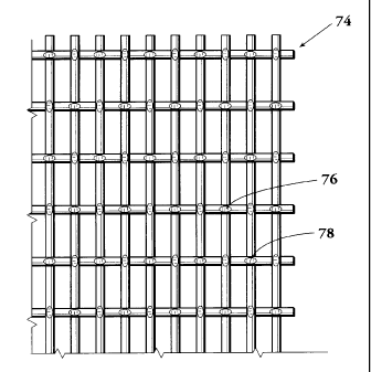
Figure 6 shows a top view of a screen cloth 74 after
completion of the calendaring process. The intersections, or
knuckle~~, such as 76 and 78 are flattened by the rollers.
Additionally, where the shute and warp filaments intersect and
touch each other, the filaments indent or conform slightly to
each other.
The conductance of such a three layer screen assembly may
be compared with both square opening screens and existing
rectangular opening screens. Table 1 illustrates a comparison
of three: (3) equivalent type screen assemblies. The equivalent
designation (such as 210 equivalents) refers to how a three layer
screen equates a single layer screen. Table 1 shows a comparison
of three layer screens of existing rectangular mesh openings,
CA 02228100 1998-O1-28
11
square openings and the rectangular mesh of the present
invention. As observed, the overall conductance (the combination
of the three layers) is improved by utilization of the teachings
of the present invention.
Each of the screen assemblies in Table 1 would have three
(3) layE:rs of screen formed in a corrugated pattern. The screens
are typically bonded to support structure.
TABLE 1
p~y~u;eng~ Shuts MeshWarp Meah shuts Dia i~arp
Dia Gos~ductam~e
210 EQUIVALENTS
Rectangular 240 150 0.0012 0.0012 2.85
105 64 0.0025 0.0025 7.70
12 12 0.0180 0.0180 52.23
OVERALL 2.00
COND=
Square 180 180 0.0012 0.0012 3.48
160 160 0.0014 0.0014 3.70
12 12 0.0180 0.0180 52.23
OVERALL 1.74
COND=
Applicants 180 85 0.0018 0.0018 4.09
120 76 0.0022 0.0022 6.43
12 12 0.0180 0.0180 52.23
OVERALL 2.38
COND=
175 EQUIVALENTS
Rectangular 205 125 0.0014 0.0014 3.44
90 50 0.0030 0.0030 9.38
12 12 0.0180 0.0180 52.23
OVERALL 2.40
COND=
Square 160 160 0.0014 0.0014 3.70
CA 02228100 1998-O1-28
12
Dger~~lngs Shuts D~eshWarp Mash Shuts Dia Warp Dia Coaductanoe
'
130 130 0.0017 0.0017 4.65
12 12 0.0180 0.0180 52.23
OVERALL 1.98
COND=
Applicants 165 75 0.0020 0.0020 4.47
105 64 0.0025 0.0025 7.70
12 12 0.0180 0.0180 52.23
OVERALL 2.68
COND=
140 EQUI'VALSNTS
Rectangular 170 105 0.0017 0.0017 4.05
76 45 0.0034 0.0034 11.19
12 12 0.0180 0.0180 52.23
OVERALL 2.81
COND=
Square 130 130 0.0017 0.0017 4.65
100 100 0.0023 0.0023 5.69
12 12 0.0180 0.0180 52.23
OVEALL 2.44
COND=
Applicants 130 60 0.0025 0.0025 5.74
90 50 0.0030 0.0030 9.38
12 12 0.018 0.018 52.23
OVERALL 3.33
COND=
It is possible that the diameters of shuts and warp
filaments may be different, although in the above examples in
Table 1, they are the same.
It has also been determined that the length of each opening
to the diameter of the shuts filaments may be expressed as a
ratio. The optimal ratio of the length of each opening to the
diameter- of the filaments is a ratio of between approximately 5.5
CA 02228100 1998-O1-28
13
to 5.7.
Figure 1 illustrates the relationship of the length of the
opening: L to the diameter of the shute filaments d. The
relationship may be expressed as follows:
d=5.5-5.7
Where "L" is the length of the opening and "d" is the
diameter- of the shute filaments. The length of the opening, "L",
is the actual opening and not the center of the shute to center
of the :>hute dimension.
As can be seen from the foregoing Table 1, the overall
conductance is greater than square opening assemblies and is 10
200 higher utilizing the teachings of the present invention than
equivalent rectangular opening screens.
It will be understood that the present invention may also
be util_Lzed with a single layer of screen cloth employing the
teachings of the invention.
As a further option, a single layer of pretensioned screen
cloth may be utilized with a backing layer.
Whereas, the present invention has been described in
relation to the drawings attached hereto, it should be understood
that other and further modifications, apart from those shown or
suggested herein, may be made within the spirit and scope of this
invention.