Note: Descriptions are shown in the official language in which they were submitted.
CA 02228124 1998-01-28
WO 97/04703 PCTIUS96/12100
DISPOSABLE ELECTRO-DERMAL DEVICE
Field Of The Invention
This invention relates to a disposable medical device
= employing electrical signals to monitor or stimulate various
parts of the body. More particularly the present invention
involves a device for establishing electrical connection to a
patient's skin containing a fixed array of conductive paths of
substantially the same electrical resistance for use with an
electrocardiological measuring apparatus.
Description Of The Prior Art
Prior art medical electrodes generally are combination
structures including a metallic or otherwise conductive
support member to which an electric wire from an assorted
apparatus may be attached. Generally electrocardiograms
sometimes referred to as an EKG or ECG have ten cable leads
which attach to various points on the upper and mid-torso of a
patient to measure and analyze cardiac data.
The person responsible for attaching the cable leads of
the EKG often has problems in attaching these multiple leads
to the patient because the cable leads may tangle with one
another or may become detached before they are all connected.
Accurately placing and securing a large number of leads can be
difficult and time consuming and requires the knowledge of a
skilled technician or physician.
Periodic electrocardiograms can provide a cardiographic
profile of a patient for early detection and diagnosis of
cardiovascular diseases. For purposes of providing an
accurate profile, it is important that each electrocardiogram
1
CA 02228124 1998-01-28
WO 97/04703 PCT/US96/12100
be taken with sensors affixed at the same location on the
patient. The accuracy of the reproducible results is critical
so that a series of electrocardiograms can be compared,
between testing episodes, to provide a continuing profile of a
patient for diagnosis and treatment of heart disease.
Although a full screen, ten electrode electrocardiograph
provides the most accurate picture for recognizing ischemic
electrocardiographic changes, however, because of the urgent
situation electrocardiograms taken during an acute symptomatic
episode of a cardiac patient are generally limited to only two
to four attached electrodes. Therefore, it would be
advantageous and desirable to have a device which enables more
leads accurately placed and quickly secured during an acute
symptomatic episode.
On the other hand it may be necessary to quickly remove
the chest cable leads of the EKG when a patient is
experiencing another heart attack in order to administer CPR,
to massage the heart, administer drugs or apply electrical
defibrillation paddles. Accordingly, valuable seconds are
often lost in removing the chest cable leads of the EKG device
in order to administer aid to the patient.
Likewise it may be desirable to remove only the
electrodes necessary to administer aid so that the remaining
electrodes can continuously monitor the electrical activity on
the heart during an acute symptomatic episode of the patient.
U.S. Patent No. 4,328,814 to Arkam teach a plurality of
electrodes attached to a single junction connector having one
cable leading to the EKG device. This device is designed for
2
CA 02228124 1998-01-28
WO 97/04703 PCT/US96/12100
an adult patient so that patients having larger or smaller
torsos will have difficulty in using the device because the
electrodes cannot be easily adjusted to accommodate a smaller
or larger torso. Also, in the event of a heart attack, the
plurality of electrodes must be disconnected from the EKG
device by disconnecting the main connectors and then detaching
the plurality of the electrodes. No electrodes remain on the
patient to monitor the heart attack.
U.S. Patent No. 4,353,372 to Ager discloses a plurality
of electrodes which plug into a junction box connected to an
EKG machine. Each of the electrodes includes wires molded
into a central cable system which joins the junction box.
This device, does not include means for quickly attaching or
removing the electrodes. For example, in an emergency
situation if the electrodes must be removed quickly, the
junction box must be disconnected first and then each of the
electrodes must be detached. Although each electrode has a
wire lead from the main molded cable, which may permit some
adjustment in the placement of the electrodes on the upper
portion of a human torso, the device is not entirely adequate
for large adults or very small children because of the limited
adjustment of each electrode.
U.S. Patent No. 4,608,987 to Mills relates to a vest-like
garment having a plurality of apertures adapted for receiving
associated electrodes. However, the vest is not tailored for
a specific patient and proper fit is provided by adjustable
straps which may be secured by VELCROR material. Therefore,
there is no assurance that the electrodes are placed at the
3
CA 02228124 1998-01-28
WO 97/04703 PCT/US96/12100
same anatomical location upon reuse with the same patient.
U.S. Patent No. 3,910,260 describes telephonic units for
transmitting ECG signals to ECG receiving equipment which
could be at a hospital or a physician's office. The
transmission may take place in emergency vehicles where prior
medical history may not be readily available. In order to
obtain meaningful and reliable data ECG signals are necessary
for the care providers. None of the prior art devices have
disclosed a low cost solution for obtaining repeatable
placement of sensors for accurate and readable ECG signals in
the field by unskilled individuals.
Because of the inadequacies of prior art devices there is
a need for a system which prevents EKG electrode leads from
being entangled; provides quick removal of some of the
electrodes while leaving the remaining electrodes in position
when it is necessary to administer aid to a patient having a
heart attack; provides accurate repeatable placement of
electrodes at substantially the same anatomical location;
accurately and repeatedly obtains signals from body electrodes
by efficient and effective electrical transmission; may be
attached by unskilled persons; and may be available in various
sizes to accommodate to fit the patient.
Summary Of The Invention
The present invention, in the broadest sense involves a
disposable non-conducting flexible sheet incorporating a fixed
-
array of electrical conducting strips emanating from a
terminus that can connect to a standard electrocardiographic
cable or.telemetric unit. The strips are used as both
collectors and'as transmitters for electrical impulses.
4
CA 02228124 1998-01-28
WO 97/04703 PCT/US96/12100
Conventional sensory electrodes are optional since the device
can function without them. More particularly, the invention
relates to a disposable, electro-dermal connector device
comprising: a flexible non-conductive sheet comprising a
fixed array of electrical conductor strips affixed thereto
having a receptor pad end and a terminal connection end said
array positioned in the configuration normally used for
electrocardial recording whereby the flexibility of said
connector and adhesion of the surface of the flexible sheet to
skin are substantially enhanced.
Each strip includes a first end portion or receptor end
adapted for electrical connection with the skin for receiving
electrical impulses. A second end portion terminates in a
common electrical connection or cable junction which is
adapted for connection with a standard type of cable junction =
for connection with the electrocardiograph device.
The conductive strips may be printed on the single layer
non-conductive film or sheet by any conventional printing or
silk screening type of process. The portion of the strip
which need not be exposed can be coated or covered with a non-
conductive coating or adhesive material which can be cured.
Conductor strips which are less than 10 micrometers in
thickness which provide enhanced flexibility without
distorting the electrical signal.
More particularly, the invention relates to a disposable
electro-dermal connector device comprising: a flexible non-
conductive sheet comprising a fixed array of electrical
conductor strips affixed thereon and positioned in a specific
size configuration normally used for standard electrocardial
CA 02228124 1998-01-28
WO 97/04703 PCT/US96/12100
recording, said conductor strips having a receptor pad end
adapted for electrical connection with the skin for receiving
electrical impulses and a terminal connection end which is
adapted for connection with an electrocardiological measuring
apparatus, wherein receptor pads V,_ and V2 are attached
approximately on either side of the sternum at the fourth
intercostal space and receptor pad V. is attached over the
fifth intercostal space midway between VZ and V. VS is
equidistant between V4 and V6. The distance between V1 and V2,
V2 and V3 and V, is about 1.75 inches 0.56 inch.
Brief Description Of The Drawings
FIG. 1 shows a preferred device of the present invention
for attachment to the torso of a patient.
FIG. 2 shows a preferred embodiment of the present
invention of properly positioning the device on a patient.
FIG. 3 illustrates the first step in the method for
determining the size of the device to be used on a patient
according to this invention.
FIG. 4 shows the second step in the method for
determining the size of the device to be placed on a patient
according to this invention.
Description Of The Preferred Embodiments
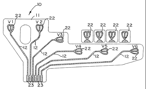
Referring now to the drawings, FIG. 1 illustrates the
electro-dermal connector device 10 of the present invention
for placement on the chest of a patient comprising flexible
non-conducting sheet 11 incorporating multiple conductor
strips 12 for connection to a standard electrocardiographic
receiving unit. The non-conducting sheet 11 includes
conductc-- strips 12 which form end sensors or receptor 22
6
CA 02228124 1998-01-28
WO 97/04703 PCT/US96/12100
which are positioned on the sheet and spaced relative to each
other whereby each receptors 22 is positioned in a specific
size configuration normally used for electrocardial
recordings.
Each strip 12 includes a first end portion or receptor 22
adapted for electrical connections with t.he skin for receiving
and transmitting electrical impulses generated by the body. A
second end of each strip 12 or the terminal connector end 23
to engage a common electrical connection or cable junction
(not shown) for connection with the electrocardiograph device
(not shown).
When in use an electrically conductive ion containing a
biocompatible adhesive gel is applied to the body contacting
side of sheet 11 at each receptor 22 of connector 12 for
adhesion to the skin of the patient for providing electrical
connection between each of the precordial ends and the
terminal end 23 connected to the proper receiving devices (not
shown).
The adhesive gel coated area of connector device includes
at least one release liner in releasable adhesive contact with
the gel. Each of the conductor strips 12 are less than 10,
preferably less than 5 micrometers in thickness whereby the
flexibility of the connector and adhesion of the gel surface
to the skin are substantially enhanced.
FIG. 1 shows the connector array (Vl, V21 V31 V41 V5, and
V6) on flexible sheet 11 which is designed to adhere to a human
torso so that the terminal ends 22 are located below the
sternal notch, over the ribs and at the side of the torso.
The flexible sheet 11 can be substantially transparent and
7
CA 02228124 1998-01-28
WO 97/04703 PCT/US96/12100
includes an opening in the proximate center which is intended
to span the upper portion of the sternum of the patient. The
sheet may include indicia adjacent to or on each of the
conductor strips to facilitate correct placement of the
receptors on the precordial areas of the human torso.
FIG. 2 illustrates the position of the electro-dermal
connector device 10 as it is properly positioned upon a
patient. The connector device 10 is generally attached by
adhering the precordial receptors. The receptors Vl and V2 are
attached approximately on opposite sides of the sternum at the
fourth intercostal space. Pads V. and V4 are attached over the
ribs. Pads VS and V6 are placed at the side of the torso so
that VS is midway between V4 and V6. For small sizes the
distance between V4 and V6 is on the average 3_5 inches, for
medium 5.0 inches and for large 7 inches. The contour of the
electro-dermal connector 10 is configured to conform
substantially to the shape of a human trunk.
In cross section a preferred laminate of the invention
comprises the following layers:
a) a flexible non-conductive film of polyethylene
terphthalate;
b) a catalyst layer in contact with silver ink;
c) a connector strip in contact with silver ink;
d) a dielectric layer in contact with silver ink and
silver chloride receptor layer superimposed upon the silver
ink layer;
e) a conductive hydrogel layer_superimposed upon the
silver chloride receptor layer; and
f) a flexible release liner as the top layer superimposed
8
CA 02228124 1998-01-28
WO 97/04703 PCTIUS96/12100
upon the conductive hydrogel.
The flexible non-conductive web or sheet 11 may be formed
from any non-conductive flexible natural or synthetic sheet
material which is capable of accepting a print. Generally any
cellulosic material, polyester, polyolefin, polyvinyl
chloride, nylon or mixtures thereof would be suitable.
Preferably, cotton, polypropylene, polyethylene can be used
because of cost. Polyethylene terphthalate is most preferred.
The polymer sheet material may be color coded for specific
body areas or may contain an outline and/or color markings to
simplify the electro-dermal connector device. As mentioned
earlier the device of this invention is designed to include
the use by an untrained or trained individual. This device
allows an untrained person including the patients themselves
to provide highly reliable and repeatable ECG signals.
The receptors 12 can be produced from any electrically
conductive material, e.g., metals, conductive polymers,
graphite, carbon fibers and the like. Conductive materials
such as gold, copper, silver, tin, aluminum, N-vinyl
pyrrolidone and alloys or mixtures thereof maybe used. The
receptors can be made of metal foil or made from a conductive
paste of a metal in particle form in a suitable binder which
is printed or silk screened onto the flexibly non-conductive
sheet. The connective polymer may be heat pressed or
otherwise conventionally adhered to the web or sheet.
Preferably, copper strips are electrolessly deposited on
the polymeric sheets in a range from about 0.25 to about 5
microns, more preferably from 0.25 to 1.5 microns and most
preferably 0.4 microns in thickness.
9
CA 02228124 1998-01-28
WO 97/04703 PCT/US96/12100
If desired, the exposed conductive strips may be
partially coated with a dielectric polymeric material so that
only selective portions are exposed, Suitable dielectric
coatings include polyesters, ethylene-vinyl acetate
copolymers, polyvinyl chloride and its copolymers, terpolymers
such as acrylonitrile-butadiene styrene (ABS resins) and inter
alia.
One form of metallic ink which may be used is a silver
ink is commercially available and marketedby Dupont Chemical
Corp. of Wilmington, Delaware under the tradename Composition
9793.
The conductive adhesive hydrogel is sold commercially by
Lee Tec Corporation of Eden Prairie, MN. Other suitable
conductive adhesives are manufactured by 3M Corporation of St.
Paul, MN. Although an adhesive hydrogel is preferred any
commercial electro-dermal adhesive would be operable.
Preferably the area size of the hydrogel is between about 3
and 9 square centimeters.
The flexible release liner may be made from a suitable
dielectric film which includes polyesters, olefinic polymers,
polyvinyl chloride and its copolymers, acrylic rubbers, ABS
resin and the like.
In a preferred embodiment the electro-dermal connector
device 10 comprises at least six gel contact areas and is
adapted for use in electrocardiography.
The electro-dermal connector device 10 is available in
sizes to accommodate any size adult person. It has been found
that the distance between pads V,, to V4 is constant for all
sizes. The separation of 1.75 inches will accommodate all
CA 02228124 1998-01-28
WO 97/04703 PCTIUS96/12100
adults with a tolerance of plus or minus 0.56 inch at each
pad. It has also been found that body placement for pads VS
and V6 vary depending on individual size. FIG. 4 shows a
method of determining the proper size. The measurement from
the V4 position to V6 position determines the size of the
= device. As illustrated in FIG. 4 this measurement is the
distance determined between the thumb and the middle finger
and then matched to a scale provided. The table below
corresponds to the illustrated scale.
TABLE
S I ZE -,V - V5_ VS - V6
Small 1.75 1.75 "
Medium 2.50 " 2.50
Large 3.50 " 3.50 "
Generally, the distance between V4 to V6 will be
determined by the size of the patient, that is, the size of
the vest. For a small vest the distance between V4 and V6 is
about 2.5 to 4.5 inches with the centering of VS being at about
1.75 inches, the medium vest has a distance of about 4.0 to
6.0 inches with the centering of V6 being about 2.5 inches, and
the large vest the distance is about 6.0 to 8.0 inches with
the centering being about 3.5 inches.
In all sizes of the devices of the invention V,_, V2, V3
and V4 are all positioned the same. The center of V1 is
located on a radius of 0.825 inches from a point 1.75 inches
= 0.56 inches from the center of V2 on the 270 (90) degree radial
from the center of V2 wherein the radial is measured with zero
degrees from the top of the device. The center of V3 is
11
CA 02228124 1998-01-28
WO 97/04703 PCTIUS96/12100
located within a radius of 0.825 from a point 1.75 inches
0.56 inches from the center V2 on the top 236 (56) degree
radial from the center of V2. The center of V4 is located
within a radius of 0.825 inches from a point 3.5 inches from
the center V2 on the 236 (56) degree radial from the center of
V2.
A typical dimensional layout for 5 and V6 relative to V4
is as follows:
Table
SIZE V- VS V5 V6
Small Vest 1.7511 1.75"
Medium Vest 2.50" 2.50"
Large Vest 3.50" 3.50"
The distance between V1 and V2 is 1.75 inches, the
distance
between sternum and V4 along a horizontal line is 3.85 inches
with V3 along a horizontal line being equidistant from V2and
V4.
12