Note: Descriptions are shown in the official language in which they were submitted.
CA 022282~2 1998-01-29
~ultipurpose hand-held implem~nLt of
the! poc~et-bnife type
The invention relates to a multipurpose hand-held
imç~lement of the pocket-knife type. ~Of the poc~et-knife
tyE~en mean~ here that the impleme~nt is to be small,
co~Lpact and suitable for carrying in a pocket and that,
whe!n not in use, there are no exposed points or sharp
edgels which could result in in~ury.
Pocket knives are often providod with a large
number of tool~: not just with large or small knife
blades, but al80 with files, screwdrivers, saws, etc. The
tools are~ usually articulated on a body and, by over-
coming spring prestressing, arel swung out into their use
position. In some~ cases, it is also possible for small
tools to be reLmLoved in their entirety from the body.
Some typeo of tools can only be accommLodated on
or in a pocket knife if compromises are made as regards
the functional capacity. For example, there are pocket
knives with swing-out scissors which, however, are then
of too flimsy a design for ~ st purposes and are also too
small for a large numLber of applications.
The ob~ect of the invention is to provide a
multipurpose hand-held implement of the pocket-knife type
which makes it possible to accommodat- tools which, up
until now, have been extremely difficult to produce, if
at ~ll, in pocket-~nife form. The term ~tool~ here is to
be understood in the broadest sense and is intended to
cover all conceivable implements or utensils which are
used as auxiliary means for work and leisure purposes.
So, for exa~ple, for caLrrying out office and
presentation work, use i8 made of a large number of
different implements, devices and hand tools, such as
stapling implements, hole p~nchers, scissors, magnifying
glasses, letter openers, adheslve-tape dispensers and 80
on. Each tool or utensil is usually ~ust provided for a
single function. Thls do~es not pose any particular
problem in an offlce, where the necessary space is
available.
CA 02228252 1998-01-29
-- 2
He~ c~, these utensil~ are often use~d in loea-
tio~s othor than an e~tabl; ~heA working area, for example
in produetion ar-a~ or wareho~P~, when travelling on
aerc,pl~Le~s or trainE~, or in a hotel, but also,- for
exa~ple, in meetings, leetures or in sehools, eollegeE~
and libraries The u~er is th n fore-d to earry along a
~ast array of uten~il- whieh are bulky and heavy, could
eauEIe in~ury and take up a lot of ~paee, for ~xample, in
baggage
It would therefore be desirable to render sueh a
piece of offiee oquipment transportable in a ccm~aet
forrl
A first aspeet of the present invention pro~ides
a mllltipurpo-e hand-h-ld implement, in partieular for
offie- wor~, h-ving a first component and a seeond
eomF~onent whieh are connected mo~ably to one another and
ean b~ mo~d betwoon a first po-ition, in which they form
toge~ther an elongate, ~~sentially cuboidal body, and a
second po~ition, in whieh aeees~ ean be g~ine~ to a frea
spac!e botween the two co~pon~nt~, moans being provided
for seeuring th- eomponent- in the first position ih a
manu~ally relea~ablo manner In contra~t to con~sntion~l
pocket tool- with only one earrier body out of which one
or more funct~ ~nal part- can be ~wung or drawn out, t~o
suehL eomponsnts are provided here, wbLieh also maLkes it
posEible to accommodate funetional parts in which two
part-tools are to bs moved relative to one another, that
is to ~ay, for ~xample, a hole pt-n~h9~ or a stapler
- A ~econd a~pect of thLe in~ention providsa a hand-
heldL implement of the poeket-knife type, eompri-ing a
firE~t component, wh$ch contains at least ono tool or tool
part, and a _~CG.~d component, which cont~ins at least one
tool or tool part, it being po~sible, for actuating at
loaEIt one tool, for the two eomponent- to be mo~ed in a
guicled m-nner relati~e to one _nother and to be brought
into a elosed po-ition, in whieh the two eomponents, with
e~sc~ntially co~y~ent contour-, form a compaet, e~sen-
tially elosed body, means b~ing pro~ided for seeuring the
com~wnents in the clo~ed posltion in a mannally
CA 02228252 1998-01-29
releasable manner A c~pact body is ae_~e~od in tho
locked ~tate; in the unloe~ed state, it is possible to
actuato one or more tools wh$ch are difflcult to provido,
lf at all, on a eo~ve~tional pocket knlfe
C~Laraetorlatie funetions for which on- tool part
i8- tc> be ~ccommodated ln one of-tho c~Lponents or sh-lls
and th- oth-r associatod tool part i8 to be aceommodated
in tho oth-r eompon nt or shell includos hole plln~h~n~,
stapling and cutting w$th a pair of seissors Tho pa~ts
required for these funet$on~ have a bear$ng on further
aspeets of th- in~-ntion
A t_ird a~pect of the inventlon provldes a
c~mhined implement having a _ole pt'nCh~~' and a ~tapl-r,
comprising a first compon-nt with functional ~lem nta of
the hole pln~h~r nd of the stapler, and a ~ or~A C ~IpO-
nent whlch contalns the othor functlonal ~lemont~ of the
hole p ~n~ Lnd of the stapler ~ d ean be movod, rela-
tlve to the first eomponont, out of an op n position, in
which the two co~Lpon nS~ are spaced apart by a di~tance
sufficient for th- ~ n-C~ Iion of paper ~hich 18 to bo
stapled or r~n~h~A, counter to the prestrea~ing of a
spring into a clo~-d pooition, in which the two compo-
nents, with essentially ~o~ ~ent contours, form a
compact, ~s~erLtially closed body, and means being
providod for securing the componont~ in the closed
position in a manually releasable mannor
A further aspect of the invention relates to a
combined imploment _aving a hoIe plln~h-r and a pair of
sci~or-, which eomprisos a first compon~nt with func-
tional ~lements of tho hole p~n~he~, and a second compo-
nent which contains tho other functional elements of the
hol~! p~ne~er and can b- ~ ~od, relati~e to the first
comp,onent, out of an open position, in which the two
com~lon-nt~ aro spac-d apart by a distanco sufficient for
tho introduction of paper which i- to be p-n~h9A, counter
to the prestre~ing of a spring into a closod po-ition,
in whieh tho two eo~Lponent~ form, with os~entially
congru-nt contoura, a compaet, essoDLtially closod body,
moarLs being pro~ided for ~ocuring the components in the
CA 02228252 1998-01-29
closed position ln a manually relea~blo manner, a~d the
scls~ors be~ng aeecmmnodated in one of the eomponents and
being displaceable out of this po~ition into a functional
posit$on, in which th-y ean be actuated by means of
relativo movement of the twv eomponents
In a eomparable manner, the invention also
relates to a combined implemont ha~ing a stapler and ~
pair of ~cissor~, c~mprising a first component with
funetional el ment~ of th- stapler, and a socond
eompon-nt which conta~ns th- other functional elements of
tho stapl~r and ean be moved, relative to the first
componont, out of an open position, in whieh tho two
eomponents are ~paeed apart by a distanee ~ufficient for
the ~ntroduction of pap-r which is to be stapled, count-r
to the prestre~ing of a spring into a clo~od poslt$on,
in ~rhich th- two eomponents, with es~entially eo~y u,ent
contours, form a eompact, ess~nt~ally elo~ed body, means
being provided for socuring the compon-nts in the closed
position in a ~An~ ly reloasable manner, and the
sci~ors b-ing aec~mndated in one of the components and
being displac-able out of thi~ position into a funct~onAl
position, in which they can be actuated by m ans of
rel-tive ~ vement of the two components
Yet another aspeet of the invent~oDL relate~ to a
combined implemsnt having a stapler and a tool, compris-
ing a first component with functional olements of the
stapler, and a second component which contains the other
functional elements of the stapler and ca,n be movod,
rela,tive to tho first component, out of an open pos$tion,
in which the two components are spacod apart by a dis-
tanc- sufficient for the introduction of paper which is
to be stapled, countor to the pro~tr~ing of a spring
lnto a clos-d po~ition, in which the two component~, with
essentially congruent contours, form a compact, esson-
tially elo~od body, means b-ing provid~d for ~ecuring the
comE~onents in tho clo~ed position in a manually
releasable manner, and th- tool being accommodated in one
of the c~yonents and being displaceable out of this
com~onent lnto a functional po~ition,-in whlch tho body,
CA 02228252 1998-01-29
in its clos-d position, forms tho handle for manipulat~ng
the tool
A furth~r aspoet of th- i-nvention relates to a
ec~blned $mplom nt h-~ing a hole plln~h~r and a tool,
eomp~ising a first eompon~nt with funetional elements of
the hole p~nrhsr, and a aeeond eompon~nt which eontains
the other funetional el~m nta of the hole p~neher and can
be movod, relative to the first ec~on~t, out of an open
position, in ~Ihi~h tho two eompon~nts ars spae-d apart by
a dl~lt~nee suffiei-nt for tho intro~uetion of paper whieh
ia to bo punehed, eount-r to th- preatre~aing of a ~pring
into a closed poslt$on, ln whleh the two eomponents, w$th
~ss~tially eongru~nt eontours, form a eompaet,
essentlally elosed body, mJans being provided for
soeuring th- eomponenta $n th- elosed position in a
manually relcasable manner, and th- tool ~eing aecommo-
dated ln on- of the eomponents andl ;n~ displae~able out
of thi~ component into a funetional- poa~Ltion, in whieh
the ~Dody, in lt~ elosed position, forms the h~n~l e for
manipulating tho tool
A further asp~et of the inventlon r-lat-a to a
combLned implement having a pair of sci-aors and a~tool,
eomp~ising a first eomponent, and a s~eond component
whieh ean be moved, rolativ~ to th- fir~t eomponent, out
of an open position, in whieh the t~o eomponents are
spac~d apart by an aetuating distanee, eounter to th-
presl:ressing of a apring into a elos-d position, in whieh
th- 1:wo eompon-nts, with ~ssentially e~ ent eontours,
form a eompaet, easentially closed body, means being
provided for securing the eomponents in the elosed
po~ition in a manually rel-asable mann~r, the ~eiasora
b~ing aceommodated in one of th- eomponent~ and being
dispLacoabl- out of this c~mponent into a funetion~l
poaition, ln wh$eh th-y ean be actuated by mean~ of
relativo mov m nt of the two eomponent~, and-th~ tool
being aceammodated-in on- of th- e~onent~ and boing
displacoable out of thia eomponent into a funetional
position, in whieh th~ body, ln it- elosed po-ltio~,
forma th- handle for manipulating the tool
CA 02228252 1998-01-29
A combined implem nt compri~ing a stapler, a hole
plnchsr and a otaple remover iB known, for example, from
the printod document DE-A-26 25 749 However, this
impl~3ment io obviously designed for use on a deok and
cannot be made into a compact body of tho pockot-knife
type
The two components or shello are preferably
desi5~ned as e~ t-, c~o~ hollow bodies which are
deli~t-d by a base surfac-, a top surfac- and in each
case two side surfaces and end surfaces
The two c~mponents are preferably of ay~ G~i_
mateLy the ~me 8~ze, aro proferably Qhar~ ~y~~ imately
symm~trlcally - nd, ln the first position or closed
posiltion, ar- locat-d ~pprox$matoly cv~y~uently on- above
tho oth-r, th-ir ba~e ~urfaco~ being d$r-ctod towards on-
anoth-r, wlth the rosult ~hat they ~form together an
essent$ally closod, compact body
Tho outer contours of the components are prefer-
ably roundod on all sid o, 80 that the $mplemont can be
held ~qually well in all use positions In this caoe, the
two s$de surfaae~ may b- flattened and set back with
reop~ct to th- outer contours of th- $mplement for the
purpose of accommodating op-rating element~, for example
slid;Lng switches, with th- result that the operating
elQments do not pro~ect b-yond th- contours of the
housing A oeparating ~oint may be provided between the
components in order that one'- hand do-s not get caught
when closing the implement A particularly pleasing form
is achieved if a ~oint which runs all the way around or
a galp iB arranged between the preferably cymmetrical
components .
Of cour~-, it i8 also possiblo for the components
to b- of different size~, in particular of different
heighto; it io al~o possible for the contour~ to differ
from on- another
Alternatively, of cour--, it iB alBo po~iblo for
the components to bo moved wbolly or p~rt$ally one in-ide
the other or one over the other and to bo o~erlapp-d
compl-tely or partly in th- fir~t pOJitiOn, for which
CA 02228252 1998-01-29
- 7 -
purpose tho contour~ of tho component~ have to be matched
with one anot_er correspQnA;ngly
In order to nsure acçes~ibility to t_~ froe
~paco between the components for ~pecific usos of the
hand-held implement, for example for stapling or hole
punching, corre~pon~;ng housing or!n;n~8 or acces~ slots
could be provided on the components in such an embodi-
ment
It would also be possible to provide more than
two ~omponents and thus to op-rate=-var$ous part-functions
o$ the h*nd-held implement, $or example hole p~nche~i~nd
stapler or a pair of sciesor~, via separate compon-nt~
The component~ may be crnnected to one another
via a parall-l guide or via an articulation which is
preferably arrang-d in th- vicin~ty o$ on- end surface of
the components and whose axis of rotat~on runs tran~-
vers1~1y with r-spect to the long~t~A~ n~l axi~ of th-
componento and parallel to the ba~e and top surfaces
The articulation ~ay be arrang-d in the cavity of
one :omponent and ~e rQ~nscted to th- oth-r component ~ia
a bearing block
In the first position, the components are loc~ed
by a loc~;ng mach~n;~m which iB preferably arranged ~t a
disti~nc- from th- articulation and can b- activat-d and
deactivatod via a manually actui~Dle loc~;ng-mechan~m
butt~Dn which is preferably placed on one of the top
surface~, in the vlcinity of the end wall locat-d oppo-
site the articulation
Tho dosign of the lOC~;n~ mechan;8m here i8 to be
selected such that, in th- unloc~s~ position, rather th~n
proj~cting ~ the base ~urfaces, wh-re lt could
ob~truct certain functions of th- ~plom~nt, it i~
locat-d bohind the base surfacos and can b- mo~ed resili-
ently b~h~n~ thoso
In a preferred ~mbodiment, lock; ng ta~e~ place
outside the freo space provided for the implement func-
tion~, for exampl- st~ ~nd hole p..~h~ for
examplo on the boaring bloc~
In order to avo$d malfunction-, in particular
CA 02228252 1998-01-29
inadvertent opening or lo~lr; n~ of the $mplement, the
loc~ng meeh~n~sm should be latched in the loc~ed and in
the unloe~ed poait$on In this ease, the loc~ing-
mech3Lnism Jwiteh may be designed~, for example, as a
slid~ng switeh with two lateh-in positions
In order to ~ ve th- eomponents from the fir~t
position into the oor~n~ position, a spring whieh io
preferably designed as a leg spring or eompresslon spring
and is arranged on, or in the vicinity of, the artieu-
lation may be prov$ded
The aeeond position io defined by a stop whiehdel$mits the ~ ~g path of the eomponents
The components are to be provided with eorre-
8pon~L~ng recesse- into which the housing sections which
run towardo one anoth-r when the implement iB opened can
move, in which case it should be ensured that the
accesses to the free apaceo, for examplo the push-$n slot
to the hole p~neh~-, remain open
In addition to the tools or utensils whose
functional el~mentJ are accommodated in both componento,
for ~c~mple stapler and hole p~n~h~r, it iB al80 poBBible
for various additional tools and utensils to be aecommo-
dated in the lndividual components, it being possible for
theoe tools and utensila to b- moved out of the compo-
nents into a u8e position from a storage position, inwhich they are essentially accommodated in the compo-
nento
The utenoilo are a ~a~e~ in the components with
their broad sideo preferably parallel to the base, top or
side ourfacea, and are mounted with rotary, swinging or
sliding action in sald components
For purpooes of swinging out or displacing the
utensils into their use pooltion, correspQn~;ng op~n~ng
oloto are to be provided on the outer surfaceo of the
complonento
One or mor- utenails, preferably arranged
parallel to one another, may be accommodatod in the
comF,onents, it b-ing poJsible for oaid utensilo to be
swu~,g out or displaced into their uoe position in the
CA 02228252 1998-01-29
_ 9 _
~ame! or oF~posito mo~ement dir-etion~ -
IrL the ease of a preferred desigrL, the
displac-able utensil~ ar- ~unted in t~Le eomponents with
their broad sides parallol to the ~ide surfaces and
restirLg directly again~t th~ latter in a longitt~A;n~lly
disE~laceablo manner, and th-y ean be displac-d into their
use positions through eorrespo~A~n~ly arrang-d opening
810t:a on the end surfac~- -
A free spae- in whLich assomblies of further
uterLsils DULy be aceommodat-d is prof-rably provided
betwe~n the utensil- which are ~ unted ~uch that thoy
rest -gJ i n~t tho side surfaees
For tbL E~Lrposo of g ~ nee in the eomponents,
th- utenJila may b- pro~ided with g~ neo eontinuations
at their - nds which ar- ~t th- rear in the push-out
direetion, said guidanc- eontinuation~ being mounted in
th- eomponents ln longit~A~n~l guid-J, for ~xample ~La
8l;~7~n~ bloeks in longit~A~n-l slots
The uJe positions of tho utensil~ are defin-d by
stops whieh d~ t tho swing-out or push-out path
Th- utenJil~ ar- fix-d in the ~tor-g- ~nd u-e
posiLtions by mean~ of ~n rlly releasablo arreoting
mean~
The arrestiLng means~y be provided indi~idually
for oaeh utensil or ~ointly for a number of utensils
Th- ~wing-in and ~wing-out or sliding mo~ements
of l;he utensils may be assi~ted by spring foree
The ut ns$1~ can be ad~ust~d via operating
el~ents which are pref-rably arranged on the side or top
surEaees of th~ ec~ponents
In th~ eaoe of displae-~ble utensils, eorre-
sp~A~ng longit~ slots are to be provid-d in the
oidl~ and/or top ~urfae--; a nu~ber of oporating element~
eouLd al80 b- assignod a e~mlon longit~Ai"-l slot
S~t-baek hollows eould bo provided on th- ~id~
and,/or top ~urfaee~ for the operating ~lements, th~
latt-r being poaitioned in ~aid set-bae~ hollows sueh
that their outer ourfa¢es are in aligsment w~th th- outer
sid~o of the top and/or sido ~urfaeea
CA 022282C2 1998-01-29
.
- 10 -
In this arrang~ment, a common set-back hollow
could be provided for a n~ er of operating elements.
In the case of utQnsil~ which are mounted in the
components such that they cian be displaced in opposite
directions, the operating element~ could be arranged such
that they run onto one another. It could consequently be
ensured that in each case only one of the two utensils is
extended .
Alternatively, the operating elements could be
arra~lged such that they are offset with respect to one
another, with the result that they could be displaced
past one another and tho extension paths of the utensils
coul~l thus be increased. The operating elements are
preferably conn~cted to the utensils in the region of the
guidance continuations and are pro~ided simultianeously
for activating and deacti~ating the arresting means. For
this purpose, the operating elements could be designed,
for example as push buttons or sliding switches or be
pro~Lded with ones with which the arresting means can be
acti~ated and deact$vated.
A central loc~i n~ means, which additionally
blocks all the utensils or groups of utensils in the
storage po~itions, could also be pro~ided. This addi-
tional loc~;ng means could be designed ac a separating
operating element or, for example, could also be combined
with the loc~n~-merhan~sm button. It is also pos~ible to
provide, for suiti~ble utensils, for example magnifying
glasls, measuring rule or pointer or writing implements,
end-~3ide grip hollows by which said utensils can be
grip~ped and drawn out into their use positions or drawn
out of the components to the full extent.
Certain utensils, for example mea~uring rule or
writing implements are preferably accommodated in the
components such that they can be remo~ed therefrom. For
thie purpose, it is possible to pro~ide channel 8 into
whicih the utensils can be pushed iand arrested or locked.
Such ch~nnels may extend over the entire length of t~he
components and be accessible via push-in slots on the end
surfaces. It is also po~sible for recei~ing com~partments
CA 02228252 1998-01-29
whieh ean be swung out of th- eomponento to be provid-d
For the purpose of r-plaeing worn or defeet~ve
uten~ , the latter may also be designod such that they
are ~onneet-d releasably to the guidanee eontinuations
For this purpo~e, the guldanee eontinuations ean prefer-
ably be moved out of th- eomponents to sueh an ~Ytent
that it is possibl- to ~Y~hAn~e the uten~ils outside the
eomp~Dnents The -utenslls may optionally b- arranged in
one or in both compon-nts with their broad ~ides parallel
to the top and bottom ~urf-co~ and/or to the side sur-
faces, and ~ueh that they ean b- swung nd/or displaeed
in the sa~ dlreetion or opposite dir-etions, in any
eo~bination~ eorre~po~ ng to th- r-quirements plaeed on
the hand-held lmplement in ~ach case
~he utensil~ may eompr~s- flx-d or ~Y~ha~geable
blades or else ~o-called ~eutter bladoJ~ with brea~-off
blade seetions, th- latt-r preferably belng mnunted in a
longit~Ain~lly displaeeabl- manner in the component and
also belng arr-stable ~n the lntermediate positions of
the displaeement path For optimum man~pulation, th-
eutting edges of the blad-s are preforably d$reeted, ln
tho uoe posltion, towards th- top surfaees of tho eompo-
nent in whieh they aro mount-d
The ut-nsils may al80 eompri~e a staple romover,
whieh preferably has a U-sh~ped eros~-seetion, the bas-
surfaee and the two lateral leg surfaces tapering towards
the free end In addltlon, th- outer end of the stapl-
remov r eould also be design~d as a serewdriver
For the best posslble manipulation, the staple
remover is preferably arranged directly on the inner side
of a top or side surfae-, i~ b-velled on its outwardly
dir-cted base surfae- and is directed, by means of the
leg surfaees, towards the longit~A~n-l axis of the
component in whieh it i8 mount-d
Th- stapl- remov-r is pre~-rably gulded ln a
longlt~ n~lly displaeeabl- manner in th- eomponent, a
8taple-det~h~ ng meanJ pref-rably being arranged at the
opening slot for the ~tapl- remo~er, ~aid detarh~ng means
mesbing with th- ~-profi}e of t_- ~tapl- remov-r and
CA 02228252 l998-0l-29
- 12 -
detac hing the staples when the staple re~over is pushed
into the implement
Furthermore, the utensilt3 may comprise a pair of
scist~ors, which is preferably mounted in a longit~ nJlly
5 displacoable manner in one of the cyonents with the
scistlor blades swung together
In the case of th- preferred allbodiment with an
articulation which i~ arranged in the vicinity of an end
surface and whose axls of rotation runs transversely with
10 respoct to the longit~Ain~ cis of tho component and
parallel to the base or top surface, the scit3sor blades
are E~referably a~ yc-l in the component such that their
broacl ~ide~ run parallel to th- sido ~urfacos of the
component and th- sci~3t~0rs axis runs parallol to the axis
15 of rotation of the articulation, th- scissors prefer~ly
being accommodated in th- component in which the articu-
lation is arranged
In order to use the scissors, the scissor blades
are moved out of the component, through an ,~ n~ng slot
20 arrang-d in tho ond wall loc~ted in the vicinity of th-
articulation, until tho ~cistort~ axis and the axil3 of
rotation of the articulation are essentially-located one
abo~re the other or concentrically with respect to one
another The scit3sor blades are extended beyond the
25 scisE~ors articulation by scissor pl -nlr~. One of the
8Ci8E~or ~h~nl~ is designed as a guidance continuation and
i~ mounted in a longit~ n~lly displace~le manner in the
component, while the second scissor shanlc, upon c~-n~n~3
of the scit3sor blade~, in the use position, moves,
30 through a r-cos~ provided in the ba~e surface, in the
direction of the other cemponent
In th- u~- position of the ~cissors, the second
scist30r shanlc is held in operative connection with the
othe~ component, for exampl-, by a scist30rs spring, which
35 pusho~ the ~cis~or blade~ or phJ~nlr~ apart from one
another or via a coupling olement, with the result t~t
the ~cissor blades can be swung open and clot3ed by virtue
of the ~vement~ of the component~ between the first and
th- t3econd posit~on~ In thit cas-, it has to be ensured
CA 02228252 l998-0l-29
- 13 -
that, to eompen~ate for the ~ v~~nt geometry, the second
8Ci8EIOr ~ l~~nlr raLain8 long~t~A;nAlly movablo witl3 respoct
to the eomponent on which it is ~o L-d or to which it
iJ eouplod When the first scissor shanlc is pushed baek
into the eomponent, the aci~oor blade connected to the
seeond scissor shank runs onto that termination edge of
the opening slot of the end wall which is directed
toward~ the top surface, a- result of w~ich the- two
scist~or blades or ~h- n~r~ are swung together and can thus
be push-d bac~ into their storago position in the eompo-
nent to the full oxtent
Alt-rnatively, of courJo, it would ~18O b-
possiLblo for the componenta to be moved into the fir~t
posi1:~on first of ~ll and for th- sei~-Jor blade~ or
~h~n~rQ, already 8 ~ g togeth-r aJ a reJult, to be pushed
baek into th- eompon~nt ther~after ~ iate eontrol
meam~ preferably ma~o it po~-ibl- for the scia~or blade~
to be coupled and uneoupled and push-d out and p~ in
in ~ly relative poaition of the eomponeuts
In order to en~ure th~t the eut ~aterial doe~ not
eollLde with the eomponent-, the aeissor bladoJ aro to be
provLded w'Lth eorr-aponA~ng defl~eting edges and the end
surfaees of the eomponent~ are to be pro~ided with
correspo~A~ng ro~n~;-' seetions, these guiding the cut
mat-rial past tho eomponents
By ~irtue of the pi~ot point of the seis~or
blades being displaced beyond the artieulation, the
dist~nce ~ n the nd surfaces and the doflocting
edg-ls of the sci~oor blades can be increaJed and the
deflection im~o~ed Additional fixed or ~ ~able deflect-
ing m an~, which can profer~bly be activated or
deacltivat-d by th- push-out or push-in ~ ~ement of the
~cis~sor~, could al~o b- provid-d on the sc$ssor blad~
and/or on the eompon-nt- Thus, for exampl-, the intro-
ductLon alot for a hol- y~r~ch~ could b- closed off rhen
the Isci~sor~ ar- in U80.
Ths ~slide for moviny the ~cissor~ b-tw en the
storage po~ition and th- U8- position iB - prefer~bly
arru~ged on th- guidanc- ~h~nk, in which case th- other
CA 02228252 1998-01-29
- 14 -
scissor shank ~8 to be provided withL a corresp~;ng
recess or is to be 4hortened, with the result that th,e
scissor blades ca~L be closed to the full exteDLt
~ Alternatively, it would also be possible to
provido a p~Lir of 4cissors which, rather tha~L beiDLg
activ~Lted by the relative mo~emLents of the components
can be pushed or swuDLg out of one of the comLpone~Lts and
io actuaLted by haDLdJ preferaLbly with the comr~nents in
ths clos-d stlLte In thi- case, the sci~sor blades are
openedL via a separate ~cis~ors spring which can be
deactivated for the purposes of retracting the scissors
into the compon~DLt or oxt~nA~"~ th m therefrom Thi~
could be carried out via ~L separate lor~; n~ membor
preferably arr~Lged ODL th- sci~sors or via the guide in
the componcnt or via control mQans, in which case the
functions of loc~;n~ and unlocking the scissors in the
outelr use positioIL and G~ n; ~ and closing the scisoor
blades are proferably coupled to one arLother
A magnifying gl~L~s could be pro~ided ~L~ a further
uten,sil, said magnifying gla88 preferably being arranged
in a plate-like mount which iB mounted displaceably in
the component with it4 broad sides parallel to the base
and top surfaces and can be displaced into its use
position through an end-side opening slot The magnifying
glaE~s is preferably pushed out by a spring and is secured
in t~e component by a loc~; ng arrangement which can be
rel~!asod on the end s$d In the guide region, the
magnifying glas~ is preferably forked or rQcessed ~uch
that there is space for additional utensils The plate-
li~e mount may comprise two pieces which are co~n~ted toone another via a pivot pin which i~ arrang-d
tr~sversely with respect to the push-out direction and
parall-l to tho plun- of the pieces, the outer piece
con~-;n;ng the magnify$ng glass, which may bo angl-d with
respect to th compone~t, th$~ consid r~b1y im~rovi~g
manipulation, in particular, in combination with a lamp
arrE~ged on the end surface
Tho uten~ may further comprise a m asuring
rul~ with ruler and tompl~to function, ~aid measuri~g
CA 02228252 1998-01-29
- 15 -
rule pref~rably being a¢eom~Lodatod 1OOB-1Y in the
eom~onents and be~ing removablo therefrom to the full
~xte!nt for cv~L~ient manipulation A push-in chAnn~l may
be p~ro~ided for aeccmmLodating this utensil, said chann~1
preferably being arrang-d ~r-etly on the inner side of
on- of the top surfaees and ~t~;ng ess-ntially o~er
the length of the ec~Lponent into whieh the moasuring rule
is push-d with its broad side parLllel to the top
surfaee
10~ Thel measuring rulo ean be ~-eured in the storago
position in tho eompon~nt by me~an~ of protrusions or a
relelasablo loe~ me nLs, aDLd it ean b- re~Loved from said
eomr~o~~nt by~an end--ide r~mo~al grip or with tho aid of
a pu~h-out ~pring
15~t-nsil~ may furth-r eomprlse a m asuring tapo,
which may pr~f-rably b- aeeommLodat-d in one of the
comp~ononts ~o as to be~ rolled up around an axis loeatod
perp,e~ndieularly wlth re~peet to the top a~Ld base sur-
faee,s, and whieh may b- drawn out of the eompon-nt
through an ~n~g ~lot providod on th- ond and/or the
side~ surfaeo~ Th- measuring tape i--pr-f-rably aLlO~y~d
outolide the di-plaeemelnt path of th- di~plae-able
ute~nLsils a, ~ycd on tho side walls, with relsult that the
maximum width of the interior of the eompone~nt eaLn be
utilized for aeeom~Lodating tho measuring tape The
melao~ur~ng tape m~Ly be provid-d with a roll-up spr$ng and
a fixing brake whieh ean be aeti~ated and deaetivatod ~ia
a button arra~Lgod pr ferably on the end surfaee
Of eourso, it would also be po~sible to aeeom-
modato the measuring tapo in tho eomponents ~o as to berolled up around an axis loeated pe,~ ;eularly with
resE~eet to the ~id- and/or end surfaeos, in partieular
when th- ~-parating plane between the eompo~Lents does not
run eentrally or the eompoDLents mo~e one inside the other
or one o~or the oth r aDLd the nee-ssary installation
heicrht i~ tkLus available for aeeommodating the ~ertieally
arranged mea-uring t-p- ~n one of th- eomponents
In add~tion, or alter~L-ti~ely, to tho m-asuring
tap~l, an adkLesi~e-tape dispenser eould also bo aeeom-
CA 022282~2 1998-01-29
.
- 16 -
modated in the eo~ponents.
In order to reeeive the ~Y~hAngeable rolls of
aclhesive tape, one of the eomponents eould compri~e a
mount with a hub on whieh the roll of adhesive tape is
mounted rotatably. The roll of adhesive tape eould then
be arranged in the eomponents analogously to the variant~
for installing the measuring tape.
In order to draw off the adhesive tape, a
through-passage slot, preferably pro~ided with a tear-off
edge!, would have to be provided at an a~ o~riate loea-
tion $n a side, end or top surfaee of the eomponent. In
the case of a preferred design, the tear-off edge eould
be aLrranged on a tape holder whieh iB eonneeted movably
to the compo~ent, could, for example, be swung out of the
eomEIonent and, in the process, moves the start of the
adhesive tape out of the eomponent to sueh an extent that
it can be gr~pped eonveniently. The inner surfaee of the
tape holder eould be eoated with a non-stiek eoating,
with the result that the adhesive tape is detaehed easily
fro~l the tape holder when the latter is swung out. The
tape holder eould lateh in the inner and/or outer
position, or else could be moved from one position into
the other by spring foree.
In order to ~Y~hange the rolls of adhesive tape,
the mount eould be aeeessible via an opening whieh ean be
elo~ed off preferably by means of a eo~er.
Alternatively, the mount could be moved out of
the component, for example on a earrier, to sueh an
extent that the roll of adhesive tape ean be introduced
into the mount or removed therefrom. It would aleo be
pos~ible for the entire adhesive-tape dispenser to be
sw~lg or pushed out of the component in order to be used.
As a further utensil, a lamp whose light-outlet
opening is preferably located on an end surfaee eould be
aec~D odated in the components.
The batteries necessary for ~upplying power to
the lamp could be aceommodated in the eomro~ent in a
battery compartment which is arranged h-h~n~ the lamp and
is accessible via an opening, for example in the top sur-
CA 02228252 l998-0l-29
- 17 -
face, whieh c n be elo~od off by a eover The lamp eould
b- switched on nd off via an eleetrie switeh arrangod
prefera~ly on the top surfac~ in the vieinity of the
light-outlet ~l n;n~.
If the ha~nd-held implement is eguipped with the
lump a~nd m~gnifying glass, tho-- eould b- arranged, in a
prsf~err-d ~m~odiment, on a eommon end surfaee or on two
adjaeent end ~urfacos, such that it is possible to
illuminat- tho ~paeo benoath the magnifying glass
ext~nded into ths u-e position
- It would alao bo po-aible, in sueh an embodiment,
for th~ lamp to be arrang-d direetly i~ the magnifying
gla~ and/or to be ~witehod on automatieally when the
magnifying gla~ $~ ext ~
In addition, or alt-rnativ-ly, to the l~r, it
would, furthermor-, bo posJible to aee~~modate a 80-
eall-d la~er pointer (llluminated pointor) in the eompo-
nents, tho light-outlet o~ n~ng of wh;eh is pr-ferably
likewia- arranged on an ond surfaee
In tho eas- of a e d ined in~tallation of l~mp
and l-aer pointor, theso are pref-rably arranged one
beside the ot_er or one above the other ~n th~ same
eomponent, provided with a eommon light-outlet op~n;n~,
fed via a eommon pow-r supply and ean be operated via a
eombination ~wlteh, for ox~mple position 1 l$ght on,
posit;on 2 push button for the laser
A pointor whieh ean bo drawn out t-leseopieally
eould li~-wise be pro~idod, whieh pointer ean preferably
be drawn out of one of tho eomponents through an end-side
3 0 _ n ~ ng~ it boing possiblo to pro~ids a push-out dsviee
by I~an~ of whieh th- pointer is pushsd out of the
component until-it can bo gripped
Ths uten~ila may also eompri~o a stapl-r, in
whieh ea~- tho functional olem~nts are aeeommodatod $n
both eomponents In th~ easo of a pr~f-rred ~mbodi~ nt,
the stapling head i~ arrangod in tho first eompon-nt and
ths an~il is arrangsd in the ~oeond eomponont
For thia ~ariant, the two compononts aro prof~r-
ably co~n~et-d to on- anothor, in tho viei~ity of ono ~nd
CA 02228252 l998-0l-29
- 18 -
side, via an artieulation, who8e axis of rotatio~ runs
tranl3versely with r~speet to the longit~A;~l axis of the
eomponents and parallel to the base and top sur$aees, the
stap1ing head as woll as the an~il being arranged in the
vicinity of the ond surfaees loeated opposite the artieu-
lation. In order to e~nsure that, even with the maximum
num~er of sheet~ being provided, the stapling head rests
properly on the ~tapling material and the latter e~not
be damaged by the e~onents, that region of the e~mpo-
nent~ whieh eontain~ the free spaee into whieh thestapling mate~rial ean be p'e~h9A is to be eorrespor~A;ngly
reee~sed, and the pivot arm on whieh the stapling head i~
arranged with an inelined ~eetion direeted towards the
stapling mat-rial i- to bo arranged in the first compo-
nent. In ordor to reeeive the ~taple bloek, the staplermechanism comprises a staple magazine which is guided
movably in the first componont. Preferably, the staple
magazine is ~ unted on the artieulation and can be
pivoted cone-ntrieally with respect to the e~pononts. In
this arrangement, the staple magazine ~8 prestressed in
the direction of the second component by a magazins
E~pring and is moved out of the first component to such an
extent that the staple dri~er is extended out of the
staple magazine beyond the height of the staple block.
The outer position of the staple magazine~ is
delimited by a magazine stop which is arranged, for
exam~ple, as a sliding ~witch on the first cc~onent
and/or on the staplo magazine and can be deacti~sted
_anually, with the result that the first component and
the staple magazin- can be pi~oted apart from o~e another
in order for the staple bloc~ to be intro~e~'.
Alte~rnatively, the path of the magazine~spring could al~o
be clel~;ted by a stop arranged in the first component.
ConE~e~qu-ntly, a magazine stop for del;m;ting the outor
positlon of the staple mngazine eould be dispensed with,
and the operation of pl~oting the first component and
~taple mag-zine apart from one another for tho
introduction of a 8taplo block eould take plaee without
the magazine stop boing d-aeti~ated.
CA 02228252 1998-01-29
- 19 -
In order to improve the acceosibility to the
staple mAgazine for i~troduction of the staple block, the
stop which del~mits the o~~~ng path of the components
coul,d b- d~acti~rated ~urthermore, it would al80 be
possible to deli_it the c~en;ng path of the staple
_ngazine by a stop on the second component and for the
first component to be moved beyond thi~ stop In the ca~e
of this-embodiment, the spring forc~ for mc~ing the
components-from the first posit$on into the s-cond
position could pref~rably be transmitt~d from the second
co~ro~nt to the first component ~ia t~e ~taple mag~zlno
In the case of this ~m~odiment, depen~ing on the de~ign
of the staple magaz~n , th- ~~n~ng path of the fir~t
component beyond tho stapl- magazin- could be delimitod
by a fixed or roleaoabl- ~Sop
In a preferrod embodiment, it is to be possible
for the stapler to be deact$vat-d Thi~ i~ necessary, in
particular, wh-n further utensils, for exasple a pair of
scissors or a hole p~nch!r, which are likewise actuated
between the first po~ition and tho aecond po~ition by the
relat~ve movements of t_e component~ are integrat~d in
the hand-held implement In this case, it i~ to be
ensured that, when the scisaors or hole p~nc!h~- are u~ed
and, of cou ~, alao when the components are loc~ed with
resp,ect to one another, the atapler remains non-acti~re
In addition, it is advantageous if th- additional high
spring force of the magazinL- spring takes effect only
when the ~tapler ia u~ed since, otherwi~e, this force
also ha~ to be overcome when the hole p~nch~r or sciasors
are used and when the componenta are loc~ed with respoct
to one another D~ n~ on tho type of deactivati~g
m c~-n;~m, tho o~erall height of the first compon-ut may
be cOn8~5 d rably reducod and, a~ a re~ult, the imploment
may b- of a considerably ~ r- compact conatruction It is
po~ible to deacti~ate the ~tapler in a nu~ber of way~
For quic~ and ~traightforward manir~l-tion of the imple-
ment, tho acti~ation and deactivation of the stapler can
ta~ place via an actuating memb~r arranged preferably on
the outer ~de of the compon~nts An ad~antagoou~ ~olu-
CA 02228252 1998-01-29
- 20 -
tion i8 obt~;ne~ by the actuating momb~r boing arrangod,
in tho vicinLty of the stapling head, in that end region
of the first compon-nt which is located opposite the
articulation The actuating membor i~ ad~ntageouoly
dosi57nod here as a push-button switch, sli~;ng switch or
rocker switch, and it ahould be not~d that, when said
switch is actuatod, the force vector is directed such
that it does not rosult in any closing ~ vement of the
open implement Th- stapler is preferably sctivated in
each ca~o only for a single stapling operation It i8
conseguently ensured that deactivation of the stapler
beforo tho implement is loc~ or bofore using other
funclti ~8 of th- implem~nt, for ~xample the hol- p~ h~r
or the pair of scissors, cannot be forgotten , it al~o
being possibl-, of course, to design the deactivating
merh~ni~m such that, after activation, the staplsr
romaLns activ for a number of st~l; ng op-rations until
such time a~ it i~ doactivat-d via the actuating member
It wDuld also be conceivable to doslgn the ds~ctivat$ng
2~ m~ch~;sm such that a seloction could bo made b-twoon a
number of functions, for example stapler off, stapler on,
~ingle stapling operation Furthermore, the stapl-r
mech ni~m should bs dosignod such that it can be acti-
vated only when the implement i~ open and activat~on
cannot tako place when the implemont is closed, since
otherwiss, when the implement is n~xt ~ the stapler
woul,d be in the activated ~tate oven ~hol-gh this function
iEI perhap~ not required at all This could bo effscted,
for oxample, by the dsactivating mechan~sm bsing blocked
when the implement is in the closed state Furthermore,
it Elhould be ensured that inadvertent loc~i ng of the
implement - for ex~mpl- a~ a result of the loc~in~-
mech~n;_m switch being displaced by mistake - i~ not
po~s~blo when ths ~tapler is in ths activated stato This
is preferably effected by the lo~n~ m~ niE~ and the
deactivating mechanism being safeguardod with respect to
one another to such a~ oxt~nt that, when the stapler is
in the activat-d ~tate,-the loc~ing mech~n~sm cannot be
brought i~to the closed position An advantageous 801-
CA 02228252 l998-0l-29
- 21 -
utio~ ~8 obt~ins~ when the lock;n~ mech-ni~m $~ designed
~uch that locking of component8 is possible only in the
closed po~ition thereof
In the case of a pr-ferred ombodiment, it would
be possible to provide, for deactiYation of the stapler,
a magazino lo~ing methanism which, with the stapler
dri~er retractetl, ~ecure- and locks the staple magazine
in the first component counter to the force of the
magazine spring Toc~ advantageously tak-s plac-
autt~natically aft-r each s$ngle use of th- stapler, and
for activation of the stapler, the magazine l~c~;ng
ms~h~n~sm is r-leased ~nl-lly Cons-t~u~ntly, the staple
magaz$ne is moYed out of the first component up to the
magaziue stop under th- action of the force of the
magazine spring and, in the process, tho ~taple driYer is
dra~ out of the stapl- magazine to such an extent that
th- I~taple block can move up towards the staple stop The
extension movement of the staple magazine could b- braked
here by a damping element After a single stapling
operation ha~ taken place, the ~taple magazine is auto-
matically locked in the first compon~nt again ~h-
magazine loc~ing means i~ pref-rably deactiYated Yia a
stapler button which i8 arranged on an outsr surface of
the componont, for exampl- on the end ~urface locatod
next to the stapling head In the case of this preferred
embodiment, the magazine lo~ing mech~nism is pre~tressed
by a spring a~d locks tho staple magazine automatically
after ~ach single stapling op-ration It is only the
deactivation of the magazine loclring mec~hani8m ~ h~rl~
takes place manually via the stapler button before each
stapling op-ration
As _as be-n ment~nf~, it would al~o bo poss~ble
for tho automatic 14~; ng of the istaple magazine to be
switched off ~ n~Dlly and the ~tapler thu~ to be switched
o~er for singl- stapling operation and ~rep-ated
stapling op-ration~ In the ca~e of these vari~nts wit~
a lc,ckable ~taple gazin-, it should be ensured that a
~taplle block which has b-en newly intrqA~q~ in the
stap~le magazino r mains at a distanc- from the staple
CA 022282~2 1998-01-29
- 22 -
stop until the staple driver is retracted into the staple
magazine. This could be effected, for example, via an
additional or movable staple stop by means of which the
stap1e bloc~ is held back from the range of action of the
stap1e driver until the latter is retracted into the
magazine, and which is activated or deactivated, for
exam~ple, by the relative movement between the staple
magazine and first component when a new staple block is
introduced.
The stapler could also be deactivated by direct
interruption in the operative ~nnn~ction between the
staple driver and staple bloc~, for example the retrac-
tion of the staple driver into the staple magazine being
prevented by a bloc~n~ member or the staple driver being
arranged movably in the first comron~nt and being capable
of adjustment from a non-active position into an active
position, for xample, by being displace~d or swung out,
as a result of which, in the case of these embodiments
too, it would be po~sible to select between nsingle
stapling oper~tion" and ~repeated stapling operationn. It
would also be possible for the bloc~ n~ member or the
staple driver to be prestressed respectively into the
acti~e or non-act1ve position by a spring and to be
guided back into these positions via a positive-control
means after each stapling operation and to be capable of
activation in each case only for a ~single stapling
operation~, for example by means of a stapler button. For
a kinematic reversal, it would, of course, also be
possible, for deactivation of the Jtapler, to move the
staple bloc~ out of the~ range of action of the ram ~nd
into a non-active position.
Finally, it would also b- possible, for
deactivating the stapler, to move the entire stapler
unit, with the ~taple magazine and the stapler driver
exte~nded out of the staple magazine, into the first
comr~Qn~nt by means of an actuating member and, for
activating the stapler, to extend said unit out of said
fire~t component. In addition, it would be pos8ible~ to
move~ the anvil nd, if nQcossary, the baJe Jurface of the
.
CA 02228252 1998-01-29
-
- 23 -
second component away from th- rang- of action of the
stapLing head, with result that thoee parte of the
stapLer unit which pro$oct out of th~ f~rst compon~nt can
move into the second component when tho implemont io
closed without th stapl-r b-ing acti~rated therehy
Howe~rer, it iB obrious that these em}~odimente result in
an i~crease in the o~rerall height of the implement
The staple magazine preferably has a ~-shaped
crosl3-soction and can b- form d in ons piece from sheet
m tal by p~nCh~n~ and l-nA~ng, In a pref~rred design, the
open Jide of th~ h ped profile is directed towards the
top ;surfac- of th~ first component in th front section
of the staplo mag~zin- and towards the second compon~t
in the roar section ad~o~ n~ ng the articulation In this
caso, the front ~-ctlon i- int~n~e~ as a receiving spac~
for th- staple block, while th- rear ~-ction is provid-d
with a rocoss, for ~xampl-, for a hol--r~n~h~r punch
guid~ arranged in th- ~ co~d c~mpon~nt and with an
actirating derice for th- punch As a re~ult of the
rec-iving Jpac- for th- stapl- block b-ing ~horten~d in
this way, th- lo-~ing slido ie prsferably pushed ~ ;n~t
t_e ~tapl- stop via a t nsion spring A particularly
compact design is obt~n~ by using a clock spring wh~ch
is m~Dunted in the lo~ng slide and, by means of its fr-e
end, iJ faJt ~ od on the ~taple magazino in the reg~on of
the staple ~top
For introduction of the staple block, it would
also b- pos~iblo for the staplo stop to b- arranged
movably on the stapl- magazine and to be pivoted away Jo
as to permit the staplo block to be introduced into the
staple magazin- on the end ~ide
Altornatively, the ~taple magazine could al~o be
d~igned ae a so-call-d ~spring compartmentR In the cae~
of 1hi~ de~ign, the etaple magazine ie ~ untQd in a
longit~ n-lly di~pl rc--hl e m~nner in an outer ~h~n~91
~ unt-d on the articulation and, upon actuation of a
reloa~- memb-r, io forced forwardJ out of the outer
channel, under the action-of the force of a push-out
spring, to euch an ~xt-nt that tho ~tapls block can h~
CA 02228252 1998-01-29
- 24 -
introdueed into the exten~e~ magazin~ from above
Consequently, it would b~ pos~ible to dispense with a
means for swinging open the m~sa~;ne and/or first compo-
nent for the introduction of staples, and this consider-
ably improves the ~t~ ;ty and man;p~lation of theimplement Dep~n~ng on th- type of deactivating
meehanism of the stapler, it has to be ~nsured that the
spring compartment can only be released when the stapler
- mechan~sm is aetivated and the nd wall of the first
component is rai~ed abov- the outer rh-nn~l to such an
extent that the spr$ng compartment can extend beneath the
end wall Th- spring compartment 1- preferably released
via an actuating member which is arranged in the region
of that end wall of the first eomponent which iB located
lS in th- vieinity of th- articulation, and which is in
operative ronnection with the spring eompartment via web~
whieh are guided laterally past the-opening spring and -
if present - the hole-p~n~hor mech~n;sm The base wall of
the outer ch~nnel has to be set bac~ in the region of the
stapling hoad to sueh an extent that, during stapling, in
eaeh ea~e the staple-outlet op~ning of the magazine comes
into contact with the stapling material in front of the
outer ch~nnel
The stapler could also be provid-d with a 80-
called flat-cl;nrh merhan~sm, by means of which a first
part-displacement of the components drives the staples
into th- pap-r which is to be stapled and said staples
are bent over thereafter ~ia a second part-displacement
of the componente In order to be able to construct the
implement to be as narrow as pos~ible, despite the
installation of such a mec~an;sm, the magazine and/or the
outer rhannel may be pro~ided with base openings which
are arranged a8 closely a8 possible to the main spring
and through which the transmission le~er arranged in the
first compon-nt pro~-cts downward~ in the direction of
the second component Consequently, the transmission
mech-nism ean be positioned between the walls of the
b-aring bloc~ and thus be protected against damage and be
accommodat-d in the implem~nt such that it i~ h~ n from
CA 02228252 1998-01-29
- 25 -
view. -
The an~il of the stap}er is preferably arrangedon the baoe surfaee of the second eompon~nt. A number of
an~ils, for examp}e for open or clos-d stapling, may be
mounted movably in the second eomponent on a ~eparate
slide or rotary plate.
Free space~ are preferably provided La~-~ae~ the
staple-magazine and/or th- outer ~h-nnel and the side
and/or top surfaee~ of the first eomponent, in which free
~paeeo lt is po~sible to aceommodate further, in par-
ticular longit~ y displaceablo or swing-out flat
utensilJ, for ~xample a knife, blade, pair of sciosor~,
staple remover~crewdriver, measuring rule or magn$fying
glass. These may be guided on the first component and/or
on the staple mag~z~ne and/or outer ~h~nn~
The loc~in~ meeh~nism for loc~ing the components
is preferàbly arranged in the space ~a~r~_~ the stapler
unit and the top ~urfaee of the fir~t component, the
operative eonneetion to the second component t~ing place
via coupling element~ which are preferably guided
laterally past the staple mag-~ine and/or outer channsl.
Finally, the utensils may al~o eomprise a hole
p--n~her, in whieh case the functional elements are al~o
di~tributod between both components. In the easo of a
preferred embodiment, the hole-p~ he- meehanism is
preferably arranged in the ~eeond eomponent and i8
acti~ated by the first eomponent during the mo~ement from
the seeond position into the fir~t position.
The hole p~ncher i~ provided with only one puneh,
whieh permits a considerably simplified, smaller and
compact construction of the hand-held implement. In
addition, the hand-held $mplement can be readily usod,
without adaptation, for the large number of ~tanA-nd
hole-to-hole distances, those differing from country to
country, and, finally, it is also the ea~e that les~
pre~sure is required for the pl~neh~n~ operation, whieh is
advantageous, in partieular, when the-hand-held implement
is used without a table for _u~6 ~. '
It would be possi~le, in the event of the compo-
CA 02228252 1998-01-29
~ 26 -
nent~ moving between the first position and the ce~ ~
position, for the hole p~n~hsr to be earried along with
said compon-nts i~ each case since no other-applicat~ons
of the hand-held i~ploment are disrupted by the hole-
p~n~he- actuation Of cour~e, the functioning of the hole
plncher could alJo, h~ Cr~ be switched on and off
The hole-r~ncher mech~n;sm comprises a punch
which i8 preferably mounted, p- ~ cularly with resp-ct
to the bas~ and-top surface~, in a punch guide a,~ugc~
on the F~C~ compon nt
It i~ also the case that, for provision with a
hol- p~nCh~ the~componeIlts ar- pref-rably eonnected to
one another, in the vicinity of one end 8~ de in each
cas-, via an artieulation whose axis of rotation runs
transversely with r-speet to the longit~A;nal axis of the
components and parallel to th- base and top surfac-~, the
punch pr-ferably b-ing arrang~d between th- articulat$on
and th end surfaees located oppos$t- the articulation,
approximately centrally with re~pect to the longit~lA;n~l
axi~ of the eomponent~ and $n the v$c$nity of the articu-
lation
The punch gu$de ad~antageou~ly forms, together
with th- bear$ng bloclc, a common assembly, which iB
fastened on the second eomponent in the region of the
base surface and extends in the direction of th- first
component, in which case corre~ponA;ng receeees ar- to be
provid-d in the first component and/or in t_o outer
~h~nn~l or in the ~taple magazine
The punch is activated by the first component or
by the staple magazine or the outer chann~l, with which
the punch c n b- brought into operative cQ~nsction
The op-rative eonn~tion can b- pro~c~~ ~ia a
carry-along member, for examplo via ~ transverse bolt
guid-d in the punch and in the stapl~ magazine and/or in
th~ out-r r~ nn91 or in the first component or via in
- each ea~e one ~eparate carry-along member for pl~h;ng _nd
pulling one or ~ r- of thes~ part~
The advantag- of this-variant io that tho punch
is guided in both movement directions with po~itive
CA 022282~2 1998-01-29
control and therefore ~amming of the puneh during puneh-
ing ean also ea~ily be released again by pulling the
first eomponent. It would also be possible, in the case
of thi~ embodiment, for the bolt to serve as a Rtop for
delimiting the opening path of the eomponent and/or of
the outer rh~nnel or of the staple magazine. Finally, in
the ease of this variant, the wear i8 redueed sinee, when
the stapler and seissors are used, the puneh is earried
along without spring loaA~ ng ~ The overall height ean be
redueed if the earry-along m~mher or members is or are
arranged above the puneh guide. In order to reduee the
.~
frietional forees whieh are eaused by the tilting ~ ment
oeeurring whon foree i~ transmitted to the puneh, the
transmission of force~ eould take plaee, for examplo, via
a eonneeting rod or via a ball mountod on the end surfaee
of the puneh. Of eourse, the puneh eould also be pre-
stressed into the non-aetive position by a eompression
spring arranged preferably in the puneh guide, in which
case it would only be the activation of the punch which
would ta~e plaee via a earry-along member.
Consequently, the first eomponent and/or outer
c~ann~l and staple magazine eould be pivoted beyond the
outer stop of the puneh, whieh would be advantageous, in
partieular, for the introduetion of the staple bloek into
the staple magazine. The eompression spring arranged on
the puneh eould also be used, at the same time, for
~ ~ing the eomponents from the first position into the
seeond position.
Furthermore, the hole-p~neher meehanism comprises
a bearing platform whieh is arranged in the second
eomponent and is preferably loeated parallel to the base
surface or in the plane thereof. An introduetion slot for
the paper sheets whieh are to be plln~h~A is provided
between the bearing platform and the puneh guide. The
introduction slot is open on the two sides direetod
towards the side surfaees and one side directed towards
the end surfaees of the eomponents.
With the same arrangement of the puneh in the
eomponents, it would be eoneeivable in prineiple for
CA 02228252 1998-01-29
.
- 28 -
aceess to be ~~~ni~ to the hole p ~n~9~ from both end
surfaces, the eonstruction of the implement being differ-
ent for the two variants The two variants also differ as
regards ea~e of u-e of the hole pl~nch~r
S If the paper is pushed into the hole pllncher from
the end surfac-s located opposite the articulation, then
the two components, for the most part, project over the
paper surface, which ma~oa it more difficult to m~ipu-
late the hol- p ncher without a table for support In
order to avoid damage to the paper sh-ets by the compo-
nents being pressed in, preferably a stop for delim~ting
the closing moYement of the components during hole
pllnrh I n~ and/or corrospo~A~ n~ rec-sses on the side and
ond and/or ba-e ~urfaces of the componentJ would hav- to
be provided CorresponA~ ng advanc mont of the punch
should preferably ensure that the pln~h~n~ operation i8
terminated before the bas- and/or side and end surfaces
of the first componont come into contact ~ith the surfac-
of the paper On the oth~r hand, it should be ensured
that, in the seeond posit$on of the components, the punch
iB extended out of the introduction slot to the full
extent
If the paper sheet~ are to be introduced from the
end surfaces located in the vicinity of the articulation,
which considerably improves the manipulation of the hole
pllnchs~, then the bearing bloe~ should be arranged in the
form of an extension arm on tho punch guide connected to
the second component In the case of this embodiment too,
the correBpon~; ng recesses should be provided on the
components in order to ensure that the paper sheets
cannot be damaged by the components when the latter are
closed Th-s- reeesaes may be in th-~form of a step-like
offset s-ction
A preferred embodiment of the imploment is
obt~n~ if th- push-in openings provided for the hole
plln~her and the stapler ar- located in a common plan- and
are at the same levels when the implement iB in the
closed position In addition, the components could be
arranged such that, in the closed poaition, their base
CA 02228252 1998-01-29
- 29 -
surfaces are ~pread apart from one another by a distance
corresronA~ s~entially to the height of the push-in
slot for the h~le pln~h~r, and the anvil and the bearing
platform for the hole pllncher are arranged in the plane
of the baDe surface of the second component In thi~
case, the paper stop for the hole p~nch~r is advan-
tageou~ly formed by the two side wall~ of the bearing
bloc~
A through-p~P~-~çe vL ni~g which is int~nAed for
the punch and ~c~ , at th- ~ame time, as a die i~
providod in the b-aring platform Arranged beneath the
through-passage oyrn~n~, in the ~ocond component, is a
receiving ~pace wh$ch i~ int~nAeA for the plln~hing~ and
can be empti-d via an opening which can be closed off by
a cover In order to ~,_v~..t ov rfilling of the r-ceiving
space, -the v~ ~n~ng is preferably arranged in the top
surface of the s-cond component, and t_e cover is articu-
lated and loc~ed such that it springs open automatically
as a result of the pressure produced in the event of
overfilling The cover is preferably ~ecured by two
latch-in positions, with the re~ult that, in th- presencQ
of excess pressure, it does not open to the full extent,
but only into tho fir~t latch-in position and thu~
signal~ the overfilled state This means that uninten~e~
emptying-out of the plnch~ng~ can be ~,_~e~ted
The dimen~ions of the punch guide and bearing
bloc~ are ~elected such that, in the first position of
the compon-nts, thi~ ass~hly can be accommodated in the
rear section, ad~oining the articulation, of the staple
magazine and/or outer ch~nne'
For lat-ral alignment of tho paper sheets, it
would bo poa~ible to provido markings, which indicate the
position of the punch, for example on the component end
surfaces arr nged above and/or ben-ath the push-in ~lot
In the case of a preferrod ombodimont a window is
arranged in the bearing platform, in the region between
the paper stop and through-passage op~n~ng for tho punch,
and the rogion of the roar sheet edge of a sheet which
ha~ been introduced into th- hole-r~n~hi ng slot c n be
CA 022282~2 1998-01-29
- 30 -
seQn from the outside through said window, via a light
guide alLauyed in the second component.
The light guide is manufactured from an optically
conductive matsrial, for example PMMA or PC, and iB
preferably of a rectangular cross-soction and in the form
of a truncated pyramid, the smaller end surface resting
against the window of the bearing platform, while the
larger end surface iB in alignment with the top surface
of the second component~ The window in the bearing
platform preferably extends up to the paper stop, while,
for stability r~r~n~, a supporting surface iB to be
provided between this window and the through-passage
opening for the punch.
The end'surfaces of the light guide may be of
lenticular design and, in order to protect against
scratching or soiling, are set back slightly with respect
to the bearing platform and top surface. A marking, which
marks the centre of the punch, i8 provided on the window
of the bearing platform and/or on that end side of the
light guide which iB directed towards the bearing plat-
form. A mar~ing provided on the sheet border means that
the p-lnrh~ng can be positioned precisely in a simple,
convenient and quick manner. It goos without saying that,
alternatively, a correspQn~;ng device could also be
accommodated in the first component. The hand-held
implement could also be provided with a sheet stop which
is preferably guided ~vably on the second component and
can be set differontly for the desired hole-to-hole
distances. The sheet stop could be ~ unted, for example,
rotat~bly in tho sQcond component and be pivoted between
a storage position, in which it is located essentially
parallel to the longit~Ainal axi~ in the component, and
the use posit~on transverse to the longit~;n~l axis. The
sheet stop could be designed w$th one or more arms, such
that it can be drawn out and/or folded via articulat$ons,
and articulated on the second component, for example,
concentrically with respect to the through-passage
opening.
Finally, for eBtabl;~hing the distance between
CA 02228252 1998-01-29
the holes, it would al80 b- po~sibl- to UBO a p~-nc~h;ng
template w_ieh is _eld together with the paper s_eets and
i8 introdueed into tho hole p~ncher together with said
sheets The pllnrhir~g template i8 preferably of an L-
~hareA eross-soction and is held in position against the
paper sheets in the eentre of the s_eot edges whie~ are
to be p~nchs~ End stops may delimit the displacement
path of the p~n~hi n~ template in the introduetion slot
The hole p~ln~h;ng tak-s plaeo in the two stop positions
io whie_ provide the desired distane- betwo n th- holes For
a guadruple pllnsh~ng operation, the pll~hing template ean
be displaeed outwards along the sheet edges in each case
by the distanee between two holes T_e p~nch i ng template
is preferably ~ unted displaeeably in a guido y~G~e,
trans~erso to the longit~ nAl axis, in a socond
componont
In the region of tho puneh, eorr-~p~n~i ng
recesses aro prorided on the pl~nch~ ng t mplate; the
centre of the p~nch;ng tomplate may ha~ro a m~rking on it
In the ease of a preferrod embodiment, the measuring rule
is designed ao a p~neh;~g template
In order to socur- the hand-held implement in a
shirt poeket or, for oxamplo, on the partition of a
compartment in a briefease, said implement may be
pro~rided with a resilient fa8t~n;ng clip. The latter is
preforably arranged in a eomplementary hollow on the top
surface of tho first eomponent, 1~hinA tho lorlr;n~-
mechan;~m -owiteh, and can ~e swung open towards said
switch
In a preferrod embodiment, the indi~idual
utensils and operating elemonts are distributed botween,
and arranged in, the two symmetrical eomponents, which
are approximatoly of equal height, as follows
The staple ~agazine and the outer eh-nnel are
arrangod in tho eentral region of the first eomponent,
extend a~ Gximately o~er the length of the eomponent,
are mounted, on the articulation, at one end such that
they ean be rotatod coneentrically with respoet to the
components, and can be activated at tho othor end via the
CA 02228252 1998-01-29
- 32 -
stapler ~utton arranged in the region of the end surfae-
The reeoiving spaee and the activating element for the
puneh and the puneh guide aro aec~m~odatsd in that
soetion of tho ~tapl- magazine and/or outer ~h~nnel w_ieh
is diroeted towards th artieulation Between the staple
magazine and/or the outer ~hannel and th- side surfaees
of the first eompon-nt there are arranged, on one side,
pr-fer~bly tho right-hand sid- as seen in the push-out
direetion, the longit~A;n-l~y-di~plaeeable seissors and,
on the other side, tho longit~A~nally displaeeable staple
remover/oe~ ivor, it be$ng possibl- for these two
utensils to be di~plaeed into their uso positions,
through openlng slots in the nd surfaee arrangod in the
vieinity of the artieulat~on, by means of the sliding
switehes a ~yed on the side surfaees ~ho loe~ ng
meeh~n~sm is aeeommodat-d between the staple magazine
and/or the outer ch-nn91 and the top surfaee of the first
eomponent Tho loe~n~-meeh~ni~m switeh is arranged in
that end region of the top surfaee whieh is located
opposite tho artieulation, and the operating element for
the spring eompartment iJ arranged in the rear end region
loeated ln the vieinity of the articulation
The c-ntral region of the seeond eomponent is
subdivided into a numb-r of seetions arranged one behind
the other The recei~ing eompartment for the p~n~h~ngs is
aeeommodated in a first section, which ad~oins the rear
end surface loeated in the vieinity of th- artieulation
Adjoining this is the window for tho positioning of the
material for pllneh~ng Aecommodated in the ad~oining
~eetion is the roll-up measuring tape, whieh is routed
laterally pa~t tho window for the hole p~neher and past
the reeeiving eompartm nt for the r-n~h~ n~ and r-~e~
out of th- eomponent through a ~lot al a~ycd on the rear
end side An arresting ~witeh for the roll-up measuring
tape i8 likewi~e arranged on thi~ rear end side Ad~oin-
ing this i~ the battery eompartment and, provided with a
light-outl-t ~ n~ng on the end surfae- loeat-d oppo~ite
the artieulation, the ~eetion for aeeommodating the lamp
and laser pointor The battery eompartment and reeeiving
CA 02228252 1998-01-29
- 33 -
spaee for t_- plln~h;n~s are aeee~s~bl- via swing-open
eovers on the top surfw e of the seeond eompon~nt The
~witeh-~ for aetuating th- lamp and la~er pointer aro
a, r ~ya~ at that end of-the top surfaee of t_e second
eomponent ~hieh is loeated opposito tho artieulation The
magnify~ng glass whieh ean be exten~A abo~4 the light-
outlet opening on the end ~urf-c~ i~ arranged between the
la~p/las-r soetion and th base surfaee of the second
componont
lQ B-tw en tho c-ntrally arranged section~ and the
side surfae~s of tho ~oeond oomponent tharo ~re arrang-d,
on one sido, tho longit~ n~l1y displae-able bnife blade
and, on the oth-r ~ide, the longit~ n-lly displaceable
eutter bl~d-, it bolng po~sible for these two utensils to
bo displacod into their uso positions, through opening
~lots in th- end wall loeated oppo~it- the articulation,
by moans of tho ~ witch-~ arrangod on the sido
surfaeos The guide for tho knif- blade ext-nds
~s~entially ov-r the entire length of the c ~pon~nt; the
guido for th- cutt-r oxt nd~ only up to the roll-up
moasuring tape, which ~xt~nds, on the eutter ~id- up to
the ~id- surface of tho eomponent Th- 8~ switehe~
are arranged in elongato, hollow-liko deprossions whieh
aro locat-d in tho sid- surfae-~, extend ~y~ oa;~atoly
over tho longth of tho e ~pononts and aro open towards
the ba-- ~urfaeo~ The hollows are symmetrieal in tho
first and ~eo~A component~ and thus form a eommon hollow
when the hand-h-ld impl~mont i- elo~-d Tho top and ond
surfaeos of the eomponent~ are pr-ferably formod from
single-pi-e- ~hell-like eaps whieh eons$st of plastie and
are positioned on tho pref-rably metal, ~-shap-d parts
whieh form tho ba~- and sid- surfaeos of the eomponents,
tho sido surfae-s boing ~et baek slightly with ro~poet to
the pla~tie eaps, with the result that the sl~
switche~ ~re loc-t-d a~imately flush with tho outor
contours of tho pla-tic caps The operating elements
a~ on the top and end surfaces are preferably
located flush with the outer sides-of-tho plastic caps
The hand-hold imploment could altornati~ely be pro~ided
CA 022282~2 1998-01-29
- 34 -
with, or additionally be supplemented by, further
utensils of cG~v~tiona~ pocket knives. The utensils
could also be a~uyed or combined differently in the
hand-held implement. It would likewise be possible for
the hand-held implement to comprise only one of the
utensils or functions of those described.
Exemplary ~mhodiments of the invention are
illu~trated in tho accompanying drawings and describod in
detail here;n'--low.
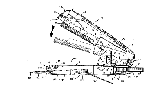
Figures 1 to 10 show a first embodiment, Figure
11 illustrates a variant of this embodiment, Figures 12
and 13 show a second, preferred ~mhodiment, and Figures
14 and 15 show a variant which can be used in the case of
ths first two embodimonts. Figures 16 to 70 inclusive
relate to a third, preferred embodimont.
Figure 1 iB a view in longit~A;r~al section of the
implement in tho open stato,
Figure 2 is a view in longit~;n~l soction of the
implement in the closed state,
Figure 3 is a cros~-sectional view on an enlarged
~cale,
Figure 4 i~ a perspoctivo oxploded view,
Figures 5 and 6 re~pectively show the implement
with sciosors and letter opener in tho use position
and/or storsgo position,
Figuro 7 shows a porspective view of tho implo-
ment with ~cissors in tho use position,
Figure 8 shows a porspective view of the imple-
ment with lottor ol-ner, cuttor and magnifying glass in
tho use position,
Figure 9 shows a ~ active view of the imple-
ment with scissors, staple remover and measuring tape,
the latter being drawn out to some extent,
Figure 10 shows a perspective view of the imple-
ment in the open stato with hole-p~nrher templato,
Figure 11 iB a partial soction of a variant of
tho hole-p~n~hsr function,
Figures 12 and 13 rospectively show tho second
ombodiment of the implement in perspective and in longi-
CA 02228252 l998-0l-29
t~ nal seetion,
~ Figures 14 and 15 are two mutually perpendicular
sectional ~iews of a variant with adhesive-tape dis-
penser,
Figures 16 and 17 ~how perspective view~ from two
~ides of a further, preferred embodiment,
F~gure 18 18 a longit~A~n~l section through the
impl~ment according to Figures 16¦17,
Flgure 19 is a longit~A~n~l ssction perpendicular
to the sectlon aeeording to Figure 18, in the ~ic$nity of
the undsrslde of ths implement,
Figure 20 i~ a cross-seetion in the vicinity of
the hole-p~nch~r me~h-n~sm,
Figures 21 to 24 ~how, in longit~ n~l section,
the implement of Figures 16/17 in four different fune-
tional positions,
Figurss 23a-23e a~e details relating to Figure
23,
Figures 24a-24c are details relating to Figure
24,
Figure 25 is an exploded visw of the 's~eleton~
of the implement,
Figures 26 to 30 ~erve to illustrate the or-n~ng
and closing mer~-n~m,
Figures 31 to 33 show a ~ariant of the loc~ng
mechan i sm,
Figures 34 to 39 show the design of slide-aetion
lo~i~g bars,
Figure 40 shows a detail of the safety loe~,
Flgures 41 to 45 ~llustrate the seissors mechan-
ism,
Figures-46 to 48 ~how a variant of the configur-
ation of the seissors,
Figures 49 to 53 show a further var~ant of the
seissors,
Figure~ 54 to 57 ~erve to illu~trate the cutter
tool,
Figures 58 to 61 relate to-the staple remover,
Figur- 62 ~hows a~detail of a variant of the
CA 02228252 1998-01-29
- 36 -
implement,
FiyUre8 63 to 65 relate to the magnifying-glass
aL ~ a~y ~ ~n t,
Figures 66 to 69 illustrate tho pllneh;ng chamber,
and
Figure 70 ~hows a ~e l~ ti~e view of an alter-
nati~o outer eonfiguration of the implement
General eon~truetion
Tho impl ment ~l-~ented h-re is a multipurpose
hand-hold ~mplem nt, in particular for offiee work The
~pl m nt eomprises a fir~t eomponent in the form of an
upper sholl 20 and a E! -~A eomponent in the form of a
low r ~hell 22 Th sh-lls r-spe¢tiv-ly hav- base sur-
fae-~ 2 and 3 whieh are d$r~et-d tow rd~ one another, top
surfaeos 4 and 5 whieh are direct-d away from one
another, side Jurfaees 6, 8 and 7, 9, and end surfaees
IO, 12 and 11, 13 The ter~ ~h~ already ;n~e~t~
that the t~o e ~ponent- have a number of ea~iti-s The
eomponents may aonsi~t of metal or pla~tie; it is al80
~ hle to ha~e ¢ombinationJ in whieh, for oxamplo,
pla~tic eovers are posltionod, preferably snapped, -onto
metal cores
Tho upp-r and lower ~ are eQnnoeted by mo ns
of an artieulation and are pushod apart from one another
by a spring arrangement Pi~ot movoments of the two
shell~ relati~e to one another permit the aetuation of
eertain uton~ils, in the prosont ease a pair of seissors,
a hole plneher and a stapler Other utensils are
aeeommodated in ca~ities of the uppor and lower shells
and, for uso purposes, are pushed or drawn out of said
shell~, of if ~ ate are remo~od co~pletely
therefrom
The upper and lower ~ rest with eongruont
eontours of th ir bas- ~urfaeos 2, 3 one above the oth r
and, in th loek-d state, form a elc~~ body of the
pocket-~nifo type Th- loeked state is seeured by me ns
of a double loe~;n~ bar 24 whieh c n be unloeked by means
of a loe~ng-m--h~ m or ~loe~ing button 26
Found on t_- top surf-e- 4 of tho upper shell i~
CA 02228252 1998-01-29
a hollow 28 in which there is loeated a elip 30 whieh i8
artieulated on the upper shell sueh that it can be
pi~oted through a small angle and whieh makes it possible
for the implement to be hoo~e~ in a poeket or the like.
A eompartment, e.g. for adhosi~e tape or adhesi~e
labels, may be pro~idod in or beneath the cllp 30.
Tho stapling mechan~sm
~Figures 1, 2, 4)
A staple magazi~e, the stapling ram, a magazine
spring and a seeuring button are loeated in the upper
shell. The two loc~ng bars of the abov~mentioned lo~;ng
mech~n~Rm are loeated on elther side of the staple
magazine.
Tho lower ~hell eonta~ns the an~il 32, whieh is
pro~idsd in a known manner with a stamped impression for
inward stapling and with one for outward stapling and ean
be drawn out of a positively loek~ n~ reeess of the lower
shell, and rotated, eounter to the prestressing of a
spring 34.
The staple magazine 36 ean be pivoted relati~e to
the upper shell around tho same artieulation as the upper
shell i8 pivoted relat$ve to the lower shell. This
element here is a part whieh has been formed by p~lnch~ng
and ~-nA~ ng and ean assume three position~ relati~e to
the upper shell: when the implement is elosed, it is
pushed into the upper shell ~Figure 2), and a spring-
loaded hook 40 pro~ided on the seeuring button 38 latehes
in and holds the magazine. Therefore, for each following
stapling operation, the securing button has to be actu-
ated first of all in order for the magazine to pass into
the operating position under the prestressing of the
magazine spring, here a leaf spring 41. This operating
position is defined relative to the ~el shell by a
lor~ng bar 42; in this position, the foremo~t staple of
a staple block 44 i~ located beneath the stapling ram and
abo~e the selected stamped impression of the anvil.
In its front, the staple-reeei~ing part 46, the
staplé magazine is designed with an upwardly open
U-profile into whieh the staples can be introduced from
CA 02228252 1998-01-29
38 -
above. In it~ rear seetion 48 eonnoet~ng $t to the
articulation, in eontrast, lt forms a downwardly open
hollow proflle in ordar to leave spaee for thè hole-
p~neher mechanism. For this reason, it would be diffieult
also to aceommodate an advaneement eomprossion spring
behind a staple bloek 44; use i8 thus made here of a
eloek spring, of which ~the free end is fixed in the
vieinlty of the staple ~top 50 and which is received
rotatably in the advaneement bloe~ 52.
For the subsequent lo~A~ ng of a now staple bloe~
44, the loe~ ng bar 42 is displaeed and the magazine
pivots into tho position indieatod by ehain-dotted lines
in Figure 1, in which the magazino is aceessiblo from
above.
A Rtiffoning bead 54, the function of which will
be expla~neA at a later point in the text, is stamped in
the conneeting section 48.
Artieulation and holo-r~n~her meeh~n;sm
tFiguros 1, 3, 4)
A single-pieeo part whieh has been formed by
plln~ing and b~nA~ng and form_ a puneh guide 56 and a
bearing bloe~ 58 is mounted on tho lowor shell. The
reetilin~rly guided puneh 60 is soated in the punch
guide and rests, by mean~ of its eollar 62, ~g~nRt the
inside of the top plate 66 of tho punch guido, under the
action of a restoring spring 64. Locatod beneath the
punch guido is a push-in slot 68 for a shoet whieh is to
be plln~hs~, and a die 70 is provided in alignment with
the punch. A chamber 72 for receiving the pllneh~ngs is
locatod benoath said die. Emptying ta~os plaee by the
flap 74 boing openod.
If the upper shell is pushed towards tho lower
sholl, the bead 54 eomos into eontaet with tho upper side
of the puneh and aetuat~s the latter, that is to say
displaces lt until it passes through the die 70 to the
full extent.
The bearing block 58 is formod by two parallel
legs of the pln~e~ and~bent part wh$ch extends in the
direction of the end~ of the shells. They have aligned
CA 02228252 1998-01-29
- 39 -
holes 76 passing through them, whieh hole~ aro eongruent
with ,~ t to oimilar holes 78 in th- ~nnsrting
soetion of the staple magazin- An artieulation bolt 80
passes through the pairs of holes 76/78, when they have
b-on position-d ev~,~ently with respeet to one another,
and the b-aring block 79 of the upper shell and pro~ects
beyond th- hol-~ 78 on oither side In oaeh easo one log
spring 80 is poait~ Q~ by m-ans of ita eoil, on said
pro~oeting ~tubJ, and tho arms of said log springs are
~upported on tho upp-r and lower ~bells Aeeordingly, the
sholls ar ps--troJ~-d in tho open~ ng diroetion Their
oponing anglo is del~mitod by interaeting stops on the
upp-r and lowor ~hell~
Slido-aetion ut~n~
(Figur-o 3, 5 to 9)
Aecommodatod in ehamb-r~ or ~h-nnol ~ 82, 84, B6,
88 of the upp r sh-ll whieh Jr- opon towards the lower
shell and on an end ~id- in ~ach eas- aro utensils which
can be push-d out of tho ao~oeiated end-sid- opening
rh~nnol 82 roeoivos a ~nifo blado (or a lottor openor)
83; ~-nn~l 84 ree-ives a pair of scissors 85; rhannel 86
receives a ~taple r~m~vor 8g; ~hAnnel 88 reeoive~ a 80-
called cuttsr 87, which is a cutting implement with
break-off part-blades Common to all four utensils i8 tho
faet that they are ronn~rted, via guided ~hJ~nlr~, to an
operating elemont in the form of a sliding button 90 The
four buttons are guided in pairs in longit~;n-l ylOOv~
of the uppor shell and are pushed outwards into latch-in
reeessoo or arresting means by springs 92 The letter
op-ner, se$ssors and staple remover only haYo an inner
and an out-r lateh-in position, wher~as the eutter ha~ a
lateh-in position for eaeh break-off blade
It ean be soon, in partieular, from a eompari~on
of FigureJ 5 and 6 that
- th- ut n~ aeeommodated on tho ~ams side of
the staple m~g~n~ aro push-d out of opposite ends of
th- imrlom nt,
- in whieh ea~e the ~liding button of on- uten~il
dolimits tho push-out path of tho othor, and
CA 02228252 1998-01-29
- 40 -
- a pushod-out utensil pr-~ents the rsspectively
other utensil from being pushed out
Apart from the faet that, in the caoe of the
cutter, a new line of blades ean be introduced after th-
last part-bla~-~ ha~- worn out - indicated at 91 in
Figure 8 - the letter opener, the eutter and staple
remover do not hav- any ~p-ci-al fe~tures
Sci~80r8
(Flgure~ S to 7)
- Besides t_e hole p~n~hor and th- ~tapler, the
pair of ac~orc 85 i8 the third utensil which iB
actuated by the two sh-lls 20 and 22 b-ing pushed
together
~ The seisaor~ eomprls~ four parts guid-d blades
100, to whieh th- as~oe~at-d oliding button is co~nscted,
articulation pin 102, artieulatod blade 104, and ~cissora
spring 106 Eaeh blade ha~ a eutting-edg- part on the
near sido, and an actuating part on th- far side, of the
seissors articulation, the aetuating part of the blade
100 oimultaneously being the ohan~ thereof Th- seissor~
spring 106 i~ arrang-d b-tween the aetuating parta and
tends to spr-ad thos- apart fro~ ono anothor; thio iJ
only possibl-, ~ .,, wh-n the ~eio~oro ar- pushed out
into their operating position because, until then, the
blade 104 rests, with its eutting-odge part, againQt the
base of the c~annsl 84 In tho operating position of the
scissors, the articulation pin of the latter is at least
approximately in alignment with th- artieulation bolt 80,
and the artlculated blade 104 is h-ld in position ag~n~t
the base aurface 3 of the lower shell 22 by the pre~ ~.a
of the sei~sor~ spring 106 When the scissors are
retracted again by meano of their aliding button, th-
scissora clooe automatically by ~irtue of the blade 104
~lnn~n~ onto the upp~r oh-ll 20
3~ Draw-out uten~ils
(Figur-o 1, 2, 8, 9)
Th- lower sh-ll 22 also contains -uten~ A
magnifylng glaoo with a lens 120 and ~unt 122, which io
aceo odated in a r-ce~ 124, ean be Jeen in Figure 1 In
CA 02228252 1998-01-29
th- p?~-h~-in po8ition (Figuro 2), a fingor-engag m nt
holiow 126 pro~octs bayond the contour of the lower shell
22 to 80me oxtont
In the space beneath the articulation, the lowor
sh-ll contain8 a roll-up m asuring tape 130 In a manner
lcnown per 8-, tho tapo i8 wound onto a hub 132 whlch is
pro~id-d with a ~-lf-locklng device and pr-stresoing
spring i34, -th- s-lf-lor~ng dev~c- boing rel-a~ed, and
tho moa~uring tapo b-ing drawn in, by pressuro on th-
r-loa-- mochanism 136~ In tho drawn-in position, a cutout
138 of th lowor sh~ll ma~-~ it possible for the end of
th-~measuring tape to be grippod (Figure 2)
Stationary uten~ils
tFigur-s 1, 2, 13)
Locat-d in th- low r sh~ll is a lamp 140, which
~ fed by button c-lls 142 or rod-typ- c~lls 144 (Figur-
13) Th- switch 142 i~ locatod bonoath tha magnifying-
glas~ rocoiving maans; th- light pas~os out through a
transparent windo~ 148 which ha~ been introducod into the
body of tho lowor ~holl In th~ ~mhodiment according to
Figure 13, a miniature laser a. ~y~ment with as~ociatod
optics 150, namely a so-called lasor pointer, serving as
a po~nting implem nt , is also acco, odated along~id~
th- lamp Th- switch 146 th n, of cour~e, has thro-
pocitions out, lamp on, laser pointer on Batterye~h~nge is made po~sibl- by the flap 152
Romo~abl- utensils
(Figures 3, 10)
A ruler, which i~ u~ually provid-d with a scale
in millim tres and/or inch-s and may then be ref-rred to
a~ a m-aauring rule, can al~o normally be found in ~n
offlco In ~e-ping with its nature, such a measuring rul-
should not bo connect-d fix-dly or mo~ably to tho hand-
held implement In the axemplary embodiment, it i~
providod that the ~ asuring rulo 160 ¢an be ramo~-d from
a chamber 162 This m-asuring rule i~ advantagoously alao
pro~id-d a~ a hol--p~n~h~- tomplate
Th~ low r sh-ll ha~ a flat y~o~e or r-ctilinaar
guid- 16~ formsd abo~- the dl-, and tha mea~uring rul-
.CA 02228252 l998-0l-29
- 42 -
has an L-shaped eross-~etion with a longsr lsg 166
~wh$eh is also provided with the graduat-d Bcal- 168~ and
a shorter leg 170. Tho longer l~g i8 dimerlsion~d to be
compleme~tary to the reet;l in~ar guide 16.4 and ean be
displae-d th-rein The measuring ruls ha~ stop noseB 172
at both end~ MG~ ,ar, in the ohort-r log 170~ it has a
triangular noteh 171 in t~e esntre b4twoen the two stops
172. Finally, two furthsr dies 174, match~ng the puneh,
ar- made in the m~asuring ruls When the measuring rule
10 rest~ against th lower ah~ll 22 by msans of ~ithor of
the etop no~-a 172, th- die 174 whieh is neare~t in eaeh
eass i~ CG~ ~ t with th~ die 70 in the lowor 8_ell The
dist ~ee botw~n the two di-~ 174 eorr~ to th~
stanA-~d wh$eh is eustomary in th country in qu~tion
Th~ border of a ~he~t 176 whieh $~ to be p
i8, then, brought to re~t aga$n~t ths short~r leg 170,
th- e ntr- of ~aid bord~r b-ing in ~l~ment with tho
tri ~gular noteh 171. Ths first pl~nCh~ ng operat$on takss
place with the first stop nose rsst$ng ~g~;nQt the lower
20 shell; then th~ sh~t 171!; and mea~uring rul~:170 are
ylG.~~' toget_er and displaeod along ths reet~linsar
guid~ until the other stop no~e re~ts again~t th~ lower
~hell, and the ~ A p--n~h;ng operation is earrisd out
Therefor~, although only one puneh is provided, a doubls
p--n~h~ng operation with a prodeterminsd distanee betw~n
the hol~s may nsverthel~ss be earried out us$ng the hand-
held impl ment
Altsrnative hol~-p~n~h~ng mech~n;sm
(Figure 11)
Manipulation of the hole-p~n~he- moehanism whieh
ha~ b~en deseribed up until now is not qulte optimum
~e~ e th- two sholls pro~et over tho paper wh$ch is to
be p~n~heA and therefore cannot be gripped to the full
oxtent Ths configuration according to Figure 11, in
which th~ aheot which is to bo p~ heA is pushed in from
the othsr sido, i~ th-roforo proforrod It goos w$thout
saying that tho configuration of the b~ar$ng block ha~ to
be adapted corr-Jrs~A~ngly and the push-in ~lot 180 hao
to b~ providod by a step on th- uppor and/or lower ~hell
CA 02228252 1998-01-29
- 43 -
In this case, of courss, the template i60 has to be
introduced in a mirror-inverted ma~ner, a~ i8 -indieated
in Figure 11
Altern4tiv- aecommodation for~utensils
5(Flgures 12 and 13~
In th- ombodiments which haYe been described up
until now, the utonsils, knife, scissors, Rtaple r~m~ver
and cutter, are all aecommodated in the upper oh ll 20
This shortens th- po~sibl~ push-out path on account of
the alid~ng buttons ;r~nntng ~g~n~t one another and
caus~- nn~ y wiA~n~n~ of th- uppsr shell, ~
it is po~ibl- to aecommodate in eaeh ea~e two of th 8-
four utensil~ in th- upp-r shell and to accommodate th
othor two in tho lower ahell, aa illustrated in Figures
12 and 13 In thi~ ea~e, th- eGll~spQ~ g sliding
buttons 190 run pa~t one another Wher-as in Figures 1 to
11 the upp~r ~h~ eonsiderably higher than the lower
shell, the two h~l 1 R ar~ a~,oA~mately of tho ~ame
height in the ~mbodiment according to the Figure~ 12 and
20 13
- In thi~ variant, th- ~unt 122 of the magnifying
glass is provided with a hing- 121, with the result that
the magnifying glass ean bo angled in order to inspect an
articlo illuminated by the l mp 140
Alternative uten~il
(Figures 14, 15)
It goes without saying that tho solection of
utensils accommodated in the hand-held impl ment was m~de
quite arbitrarily and dep~nds largely on the int~
use Therefor-, an adhesive-tape dispenser, for example,
may be aeeommodated in plaee of the roll-up measuring
tape, as i8 illustrated in Figures 14 and 15
Integrally formed on the lower sh-ll is a hub 200
on wh~h a roll of adhesi~e tape 202 may be positioned
after a resilient or loc~abl- flap 201 has been opened
An outlet slot 204 permit~ th~ through-passage of th-
adhesive tap- ~he ~lot 204 i~ d-limited at the top by
the free LGL~~r of a flap 208 with a toothing arrangem~nt
206, on whieh the adhe~iv- tape can be torn off The
CA 02228252 1998-01-29
re_aining strip end the~ eomee to rest on the bead 210
If the flap 208 i~ drawn outwards, it is possible to grip
caid ~trip end; when th- flap is closed, th- adh-~ive
tape forms a loop, and th- t~ ney of the latter to
stiek to the inside of th- flap can be minimized by said
flap b-ing eoated w$th Teflon or the like
The following figure~ sho~ a preforred ~mbod;m-nt
- with a number of ~ariant~
The implement has an ~ r shell 300 and a low r
sh-ll 302, but thQse refer~ee~ are seleeted only in
ord-r to distingui~h b-tween th two shells, sinee th-y
do not a~sume any particular spatial position for use
The two sh-ll~ ar- loeated oppo~ite one another in an
essentially mirror-~yl~-trieal manner and eaeh ha~e
ro~nAs~ contour~ which are sym~-trical with respeet to a
longitv~n~l plane and to a tran~v-rse plane Th- outer
~ide of one of the shells may be flattened to some extent
in order to pr~vent the implement from wobbling wh-n it
i8 set down on a table
The two sh 11- are s-parat-d by a peripheral
~lot, it being pos~ible for the shells to b- mo~od away
from ons another at an end V referred to as the front~
in ord-r to bring th- stapling ma h~n~m into the operat-
ing position, while th- push-in slot E for th hole
p~ne~or i~ at the nd H referred to as the ~rearn At
this end, th- upper sh-ll is pro~ided with a bev-l A in
order that the paper which is to be plln~ho~ ean also bo
pushed in when the implement is open On the end sides
(front and rear), the outer contour of th- shells tap-rs
to a very pronounc-d extent The side surfaees S are ~et
bae~ and oss-ntially planar Th- contour of the two
shells is sueh that plln~h~n~ and stapling ean ~ ly b-
earri-d out with one hand and without ha~ing to ~et the
implement down on a ~a~e, while, in the loeked stat-, th-
sh-ll~ ean ~ ly b- h-ld in the hand as a handle for a
tool The implement eomprises a series of utensils
illu~trated in Figure~ 16 and 17 a~ w ll as further
utensil~ whieh will b- clarifi-d in the deseription in
due eourse A stapling device and a p~nchi~g de~rice are
CA 02228252 1998-01-29
provid-d in tho l~terior of the implomont which ~
illustratod in th- elo~ed-stato ln F$gures 16 and 17 Tha
following aro al~o provid~d a ~nife 304, a eutter blade
306, a pointor 308, a~magnifying glass 310, a otaple
5 remover 312, a pair of ocl~sor~ 314, and a tape measure
316 Instead of tho pointor, it is also possible for a
so-called ls~er pointer to b~ provided The ~n$fe, cutter
blad-, seissors and staple romovor are d~splacod outward~
from the intorior of tho implomont, and al-o drawn bae~
again by m an~ of olid--actlon loc~ bar- 318
Tho baJ$c con~truction of tho impl-mont ean bo
sa n from Figur-~ 18 to 20 A m tall$c ~keleton~ with an
upp-r part 320 and a low r part 322 formo tho reeeiving
m ans for, and/or parte of, tho ~tapler and holo pln~h~r
and delimits ~paco~ for roco$ving the other utensils Tho
upper part and low r part ar- eaeh providod with a
p}a~tie eap which i~ fa~ten-d at L~ iato locat~ons
Threo oporating oloments are loeatod in tho upper
cap 324 a main button 326 for loeking and unloc~ng tho
upper and lowor parts, a staplor-aetivating button 328,
and a magazine-unloe~ng~button 330
In the lowor cap 332, lt iB possible to see a
magnifying-glass rolea~e button 334, two mic~v_riteh
buttons 336, 338, a disengag$ng button 340, a flap 342
which givos acQ-~s to a battory aompartmont, a l$ght
guide 344, and a flap 346 ~rhich pormits empty$ng of tho
chamber 348 into whlch the p~n~h~n~s produeed by the holo
p~n~ho~- pa8B. The tapo moal~uro 316 i~ prov$dod w$th the
c~v~tional restoring me~hanism (not ~hown) and with a
bra~ing lever 350 which can be displacod manually into a
relief position eountor to the prostre~sing of tho ~pring
351 A~ ean bo ~eon in Figur- 19, the chann-l 3S2 whieh
rocoivo~ th~ ~nif- 304 oxtend~ virtually ovor tho ontire
longit~ nal oxtont of th- $mplement, whllo tho ~h~nnol
354 for tho cuttor blade 306 i8 only virtually half as
long; this providos spaco for the d$ameter of tho tapo
moa~ure 316, whieh in thiH way can achievo a draw-out
length of, for examplo, 100 cm The two button battorie~
356 and a lamp 358 can al~o bo ~oen in Figure 19, wh$1O
CA 02228252 1998-01-29
- 46 -
the laser pointer 360 is located behind the microswitches
336, 338
Referring now to Figures 21 to 24, th- stapler
will be d-scribed first of all Tho stapler is a 80-
called flat-clinch stapler, that is to say a stapler in
which flrst of all the staple is driven into the paper
which is to be stapled, and the freo ~taple end~ are only
folded over when the Jtapl- driver ha~ re~h~ its nd
position Figure 21 shows the implom nt in th- closed and
locked state Th- main spring 362 prestressos the upper
part and lower part in tho opening dir-ct~on Figure 22
~hows th- open implement, in tho case of which, horc~e ,
the staple m-g~7~ne is not yot in the op-rating position
In Figure 23, tho staple magazine i~ r-loa~-d, and ~n
Figure 24 t_- staple carr~er is r?~rh~ out
The stapling proceduro will be expla~ne~ t~tng
Figure 23 as departur- point
Tho stapler i8 rendered op-rational by pressure
being exerted on th- button 328 The button i8 articu-
lated at 364 and i8 pre~tre~s~-d into its r-st po~tion by
the leg spring 366, in which rest po~ition it ongages, by
means of two hoo~s 368, over two pins 430 (illustrated in
Figure 25) which are provided laterally on th- outer
channel 370 in which the ~taple carrier 408 i~ guid-d
When the button is actuated, the outer ch~nnsl is
released and pas~es, under the action of the leaf spring
372, into the position according to Figure 23, whore it
strikes, by way of nose~ 374, -g~;n~t the end of slots
made in the staplo driver 376 The stapl- driver or the
knife 376 i~ formed in o~e plece with the l-af spring
372
It should be noted that, in th- position accord-
ing to Figures 22 and 23~ the outer rh~nnel 370 r~sts
against a stop 380 by mean~ of one end 378 Accordingly,
when th- button 328 i~ actuated, the upper part 320 movea
upwards instead of the outer rh-nnel ~ ving downwards;
however, since the implement i8 generally not ~upported,
but i~ held freely in the hand, th ~olt produced by the
fairly powerful l-af spring 372 i~ damp-d partly by the
CA 02228252 1998-01-29
- 47 -
~ain spring 362 a~d partly by the _and $tself A separate
damper i~ optional A dou~le transmission lever 384 for
t_e flat-clinch me:h~n~sm ean be pi~otod around a bearing
386 and is prestressed by a spring such that its longer
ends 387 alway~ rest -g~in7t the upper part 320
In the lower part 322, tho anvil 3B8 is Jupported
on a w~b 389 and ~n~ho~od thc~aG~ Its operation surface
i8 loeated ~~sentially flush with the upper sid- of the
lower part In th- position illustrat-d in Figure 23, the
10 anvil 388 i8 fully~enelo-od around th por$phory by a
pla~t$e platform 390 wh~ch ean b- pivoted around an
articulation 392 pro~rided on the lower part and is p-~h9A
against a stop ~not shown) by a eompr-s~ion spring 394
In t_i~ arrangement, th-- platfor~ i8 supported on a
blor~g angle 396 ~Ih~h, for it~ part, ean slido
parallel to the upper sid- of the low r part and ie held
in position again~t the an~il 388 by a ¢ompr~ssion spring
398 The upper s$do of that seetion of tho platform 390
whieh eneloses th- au~r$1 is high9~ than th- oporating
surfaee of the an~il by t_o longth of the stapl~ legs
If a stapllng op-ration i8 to talce plaeo, tho
paper whieh is to b~ ~tapl-d is introdueed into the gap
betweon tho lower and uppor parts and the i~plement i~
elosed Th- stapling head eomes to be positioned on th-
pap-r _~,Led on the platform, with tho result that, as
the elosure mo~ement eon~n~ , it is pushed baek into
the upper part eounter to the fore~ of the loaf spring
372 In this proeess, the staple driver forees a staple
out of the staple earri-r and into the paper
Consequently, the transmission lever 384 is pivoted; its
pivot po~ition is thus repres-ntative of the angle
betw -n tho outer rhannel and upper part When the lever
ha~ ~_~rhed a position eorre~rQ~A~g to the staple hav$ng
boen pushod out by ~he stapl~ driver to th- full ext nt,
it has displaeed the upright legs 400 of the blor~
angle, eount-r to th- foree of its prestressing spring
398, to sueh an ~xtent that support i~ withdrawn from th-
platform 390; th- latt-r i~-p~rheA down abruptly by th~
uppor part, and th- ~ro- l-g~ of th- stapl- which pro~-ct
CA 02228252 1998-01-29
- 48 -
beyond the paper which has been introdueod ar- folded
ovor in the proe~ss In this eas-, the outer ehAnn~l
automatieally hoo~s into tho hoo~s 368 of the-button 328
again For each stapling operation, thio button thus has
to be reacti~rated It goes without saying that this iB
not absolut-ly necessary a lateh-in recess, for example,
could b~ pro~idod for th~ button in order to hold tho
latter in th- reloas-d stat- for a number of stapling
operations
Mount-d in the outer rh-nn~l is a slido rod 402
on which ther- ~8 ~oat-d a thru~t spring 404 whiah, ~ria
the slide 406, pusheo the staple~ eontA~no~ in tho staple
earrier ~08 forwards }f a lsr~n~ means, which will ~e
explain-d in dotail ~ / is released, tho sprlng 404-
p~Rhs~ tho otaplo carrier 408 outwards out of tho outer
eh-nnol 370 to ~uch an oxtent that it can be drawn out
and 1~-~ wlth a now stapl- ~loelc; thl~ posit~on iJ
rspre~ented in Figur- 24
The outor ch-nn~l ~ staplo earri-r, slide rod,
~lideo and staple bloc~ together form tho stapl- maga-
zine
Figures 23a to 23c show, on a further-enlarged
~cale, tho kinematics of the unloc~;ng op-ration for the
staplo magazin~ -
Figures 24a to 24c show th- int-raction of the
unloe~ n~ button 330 for the staple carrier with the
fork-shaped oxtonsions of the latter; fitted on the
button 330, whieh ean be pivoted around the artleulatlon
331, are small bolts 333 whieh, in the ev-nt of pressure
being exerted on the button, are lifted out of tho hoo~s
434 of tho staple carrier and eonsequently release the
latter Whon th- ~taple carrier i8 pushed in again, tho
hooks automatically latch in aga~n Tho button 330 18
prostrossed into its rest and latch-in position by the
spring 335 ~-
Tho abo~e de~cribed deaetivation of the staplingmechAn~m serve~ primarily to a~oid the situation where
a otaple is lost ~uring overy othor actuation of the
upper and lower sholl~, for examplo during hole p~neh~ ng
CA 02228252 1998-01-29
- 49 -
or actuation of the scissors The seleeted d-sign in
whieh the outer ch~nnel iB set bacle in the upper part i~
advantageous in~ofar as the stiff stapler spring 372 $~
also deaet~vated thereby, which spring would otherwise
counteract the actuation of the hole p~nrher or of tho
scissors Furthermore, the implement iB compsct in the
closed state However, there are, of eourse, other
po~sibil$tie~ for deaet$~ating tho stapler displaeing
the staple driver such that it no longer eomee into
contact with the staple loeated in the magazln-, bloc~ing
the magazine advaneement, blor~ng the relati~e movemont
between the upp-r part and ~taple magazins, setting back
the upper part and magazin- into the upper shd 1 to sueh
an extent that th dri~-r no longer reaehos th- an~il,
and, finally, disp~a~ng the anvil- sueh that, in th-
closed po-ition, the tip of th- stapl- remain~ froo
Tho functioning of the hole p~Ch~ will now b-
eXpla~ne~ with referenco to Figures 21-24 Convent~
hole p~nchers for us- in the off$ce ~r- pro~ided with two
or more r~n~he~s, whleh are set to a sp-eifle spaeing of
the filing meeh-n~sm~ while the implement aeeording to
the invention has only on- puneh SineQ th- i~plem nt ia
coneeived, in partieular, for UBe outsido of the aetual
offiee, the hole-p~n~her funetion will b- us-d wh~ var
there iB a file to hand in whieh tho rolevant paper i8 to
be filed The user, then, takes the paper which i8 to b-
filed and rests it on the filing meCh~n~R~ and m r~
e g with a peneil, the loeation~ wher- holes are n-ees-
sary, to be precise direetly on tho border of the sheet
An arrow or the li~e eould be provided on the outside of
the implement in order to mar~ th- eentre of the punch
How ~er, due to the relatlvely large distanee of the
puneh from the outer eontour of the implement wh-re sueh
a marking would be pro~ided, this results in inaceur-
aci-s It is th-refore pro~ided that the ~he-t (or
sheets) which is to b- r~nche~ ~8 introdueed into the
slot 410 with the mar~ing downward~, the light guide 344
ma~ing it possibl- to ~e- tho mar~ng from the outsid-;
th~ light guide i~ pro~id~d with an arrow or th li~-
CA 02228252 1998-01-29
- 50 -
whieh i~ i~ alignment with the puneh axis It go-s
without ~aying that the light gu$de neod not n~eessarily
bo guided to the puneh platform from below sinee, in a
~ariant, it eould also projeet onto the paper from abovo
(here, the term~ above~ and nbelow~, as has already beon
~xpl a; n ~ ~, rolato only to the graphie illustration and
not to the use position of ths imploment) In prineiple,
the light guido 344 eould also be replaeed simply by a
hole, through which one eould seo tho paper whieh ha~
b-en pushed in Ho~ ~c-, it is preferr~d to de~ign tho
light guido from transparent plastie, its eross-soetion
preferably boeoming larger towards the outside To
proteet ~galn~t seratehing~ it~ two endo are ~-t baek
slightly L-ntieular eurv-s whieh -ha~o an nlarging
aetion eould b- intogrally formod at on- or both end~
The light guido is pr-forably r-etangular in eross-
seetion
Tho puneh 412 i~ guided reetilinoarly in a hole-
eont-~n~ng ~. r~st 414 and a boro or a pln~h~ holo 416
of a bloek 418, whieh will b- d~serib-d in detail at a
later po$nt in th- t-xt Foree tran~m$ssion to the puneh
412 takes plaee by a stamped tongue 420 of the upper
part, while said puneh is earried baek upwards by tho
outer ~h-nn~l; for this purposo, th- puneh i8 pro~rided
with a snap ring 422 introdueed into a y~oova of the
punch This design sa~es spaee in eomparison with the
eon~entional design, in the case of whieh the puneh is
pro~ided with a restoring spring
Figuro 25 shows an exploded viow of the ~skele-
ton~ of the implement The upper eap 324 and low~r cap332 aro plastie parts, preferably $n~ection ~ uldod from
impact-resistant plastie, whilo the rest of tho parts of
the skeleton are each manufactured as parts which have
be~n formed by p~lnCh; ng and ' n~ n~, proferably using
metal or ehromium steel Th- upper part 320 i8 bent at
right angles three tim 8 on either side, this produeing
a eentral s-etion and, adjoining this laterally, pairs of
re~peeti~ely parallel flanks 424/425, 427/429, whieh for~
tho guide ~h~nn~l ~ for the displaeeable tools ~seissors
CA 02228252 1998-01-29
- 51 -
and staple romover) Tho e-ntral, planar section i~
provided with r~c-sses and doformations, tho purpo~o of
which will be ~xplA;nsA at a lat-r point in the text The
inner bent flan~s 424 und 427 -aro ext ~o~ to the roar
(nrear~ is the hole-p~nch~- end) and are provided with
align-d b-aring bor-~ The outer ~h-nn~l 370 has an
upsid--down U-Jhaped eross-soetion and is provided with
an anglod tonguo 426 on whieh the ~lid- -rod 402 i~
fastonod; inwardly proj-cting lug- 401 for ~u~o~ing th-
staplo carrior aro loeat-d at tho front end An aperturo
428 p-rmit~ th- through-r~lF-ge of th- puneh with its
spring ring 422, whieh i~ push-d on abov- the aperture
after tha introduction of tho puneh with tho re-ult that
it can pa~ into oporativ- e~nnqetion with th- tongue
420, integrally form-d on tho uppor part, in ordor for
th- puneh to bo ~ctuat-d Th- pins 430 intoraet with th-
stapler-r-l-a~- button 328 Tho ro_rward oxte~ion of tha
two U-leg~ is pro~idod with boaring bor-~ 432
Tho stapl- carri-r 408 i~ U-shaped in cro~s-
section, and its U-log~ are- oxtended to th- roar and
provided wlth hooks 434 which intoract with th- bolt 333
of the button 330, a- ha~ b-en expl~;ns~ abov-
Th- block 41B i8 a furthor part which ha~ been
formed by p~nCh~n~ and l-nAin~. It ~upports th- b-aring
journal 436 around which th- outor rhAnnol and tho ~p~
part can b- pi~oted Th- boaring ~ournal 436 iB arrang-d
in pro~ecting ~ide wall~ 440, benoath which thore i8 a
free space for the introduction of paper which iB to be
p~nch9~. Tho v-rtical edge~ at the end of thi~ free Bp~C-
form the stop 458 Ag~n~t which the pap-r can be po~i-
tion-d Th- s$d- wall~ ar- eonn~cted by a tranov~r~-
m tal plat- 442, providod with tho lowor punch guido and
arrA g-d abov- tho papor ~lot The bracket 414 i~
faston-d, e g spot ~ ', on the tran~vc._a metal
plate Th- block ha~ a foot part 444 by moans of which it
is c ntrod in tho low-r part, on which it i~ fa~toned,
mG.oGvor, by means of spot welding or eontinuous ~oining
The configuration of th uppor bord-rs of the block will
b- d-scrib-d bolow in eon~unction with the loc~ ng
CA 02228252 1998-01-29
mechanism.
Tho lower part 322 comprises two metal sheets
which are angled in an up~ide-down U-shaped ma~er and of
which the upper shoet-motal angle 446 has the die 448 for
S the hole p nth;ng~ a r-coss 450 for the through-passage
of the light guido 344 and the introduction of the block
foot 444 and a through-passag~ opon~ng for the spring
362, as well as an apertur~ 452 into which the platform
390 can be displacod Th- configuration of the angled
legs 453, 455 will bo expl-~n-~l at a later point in th-
text in con~unction wlth tho displaceablo uten~ils
Th- lowor ~heet-motal anglo 454 i8 co~nect-d to
the upp-r ono, for ~xamplo, by spot w~ ng. It has an
a~e~-~ro 456 for the through-pas~ago of tho p~n~h;r~gs of
the holo p~nch~r and the rec-ption of th- light guid-, a
set-back hollow 43 8 for o~G~l-ing tho main spring 362,
mounting holes 460 for the block foot, and an ap-rture
462 whlch corrospond- to the aporturo 452. The main
spring 362 i- supported in the e-t-back hollow 438
(Figuro 22)~ and th- othor -ond of said Bpring i8
~G~Lod on the outer ch~nns~, between the punch and the
tongue 426; the ~pring i~ 80 short in compari~on with its
diamoter that there is no need for any special mea~uro~
against buckling of tho spring The two vl -n~ng8 464 in
the upper sheot-metal angle and 466 in the lower ~hoot-
metal angle permit tho through-passage of ths ~rertically
bent part 400 of the blocl~ng ang}e 396. The anvil 388,
which con~ists of hardonod stool, is pressod lnto an
insort 468, which, for itB part, is connected to the
lower sheet-motal angle 454 by comprossion or somo other
moans Th- low-r sheet-metal anglo i8 narrower than the
upper ono, with tho rosult that a guide h-nnel for
receiving furthor displacoable tools (knife, cutter~ is
dolimitod in oach cas- betwoen the angled legs 457, 459
of the innor ~hoet-motal anglo and 453, 455 of tho outor
shoot-metal anglo Tho lower ~hoet-metal angle has, in
tho angled log 459, a cut-out 470 which rol-~es tho
latoral spac- necossary for tho tape measure
It can b- gath-r-d from tho above de~cription
CA 02228252 1998-01-29
- 53 -
that the upper part has a ~hann~l delim$ted by the angled
flanks on either s$do of tho spaee neeeosary for the
stapling meehan$~m, and that the lower part also hao
delimited rhrnn~l8 on both sides of the pairs of legs
It ean be seen that, both $n the upper shell and
in the lower shell, the expos-d, vi~ible, outer side
surfacos of the metal parts form angled seetions whieh
delimit ths inner r~nn-ls for th- utensil- and proteet
the latter towards the out-ide Consoquently, at the oame
timo, the ~tab$1ity of tho implem~nt ean be inereased and
minimization of th- width of the components ean be
achieved
It will now b- dseeribed, with refer~neeo to
Figur-~ 26 to 30, ho~ th~ two ~hgll~ $n this ~xemplary
~mhodiment are loek-d and unloeked with respoet to one
anothor When tho tmpl~m-nt i~ clooed - Figure 28 - the
button 326, whieh, for ~nlor~ng ~.L~ e~, is f$r~t of
all pushod in eounter to the forco of a spring tongue 472
and is then displaeed to tho rear, that is to say in the
direetion of the hole pl~n-~h~r, pro~oets to a vory slight
extent out of the upper shell The tongue 472 is
integrally formed on a l-af spring 474 wh~eh is a~ yel
on the upp-r sido of the uppor part 320 and is held, and
guided, thero by tabs 475 which engage over it Pro~oe-
tiono 476 on the upper edges of the bloek 418 engage, in
the loeked state (Figur-s 28 and 30), over latoral lugs
465 of the leaf spring 474, which aro roleaoed from the
pro~ections when the button is displaeed in the o~-n~ng
direetion When tho leaf ~pring $8 displaeed, lugs 478,
whieh are integrally formed thoreon and are provided at
their ends with a downwardly diroeted nose, run over
tines 463 (mark-d in Fi~ure 25) whieh are integrally
formed on tho upp-r part,-with tho result that the leaf
spring ean only as~ume two stable positions lor~ ng ond
position or unlor~ng nd position A tongue 480 is eut
out at tho end whieh 1~ direeted away from the button
326, ~a~d tongue being angled ~ rds and, in the
unlocking end po~itlon, l~teh~ng into a reees~ 479 of the
uppor part 320 Thu~, as ~oon a~ th- ~mplement is G~
CA 02228252 1998-01-29
- 54 -
the leaf spri~g 474 ca~ ot b~ displaeed into the loel~ n~
end posltion again It io only when the two shells have
b-en brought into th~ elosed po~ition shown in Figure 27
that the protru~ions 482, integrally formed on the bloek,
li$t the tongue 480 to such an extent that it is released
from the r~cess 47 9 and ths implement ean bs loeked by
ths button being displaesd baek; th- sseond reeess for
the s-cond protrusion 428 h-1PnC88 th~ lift$ng of ths
tongu- 480. Th- oolution pr-s nt~d here iJ preferr-d on
aeeount of its ~impl$eity Alternatirely, the bloel~; n~
mean~ eould also be dispen~ed with and be replae~d by an
automatic loe~;ng means on the bloek, sa$d lo~;n~ m-uns
t-~ing eff-ct as ~oon a~ tho button 326 - e~n in tho
ca~e of the impl ment b-ing opsned - iJ displae-d into
tho cloo-d poaition In thi~ ca~, h~_~c~, $t would be
noe~ssary to bloek the stapler-reloa~- button 328, on the
one hand, and tho ~iu button or l~e~ing button 326, on
th- oth-r hand, with r- p~ct to on- ~nother if tho
implsment i~ lo~ ' when th~ stapling meeh-n~sm i8 in the
roleao~d state, a loooe doformed stapl~ rem~in~ in the
spaeo abo~e the an~il and, if ~tapling mat-rial is still
loeat-d betwe n the upper and lowsr shells, then, when
the implem-nt loeks automatieally, said upper and lower
shells eould be sprsad apart to such a pronouncsd extent
that it i8 no long~r possibls to op ~ tho impl ment It
~hould also bo noted that although, wh-n the implemont is
elosed, it iB possibIe to push th~ button~ 328 and 330,
the staple magazine and the stapl~ carrier latch in again
wh~n th- buttons ar- rel-as-d, and ~o the de~ign illus-
trated in F~gur- 26 remains intaet wh-n the implement i8
5~r~ngA .
Aecording to Figur~ 24, the release button 328
for the stapling me~h-n~m i8 artieulated at the top
HowevQr, th~ alt~rnative dosign illustrated in Figurss 31
to 33 is pref-rr-d There, th~ button ~ v-~ ~rearwards~
rath-r than downward~a Ths button 328 here has a stop
surfaeo 484 by means of which it rest~ against an abut-
msnt surfaes of ths lin~ 486, whieh i~ pr-streosed into
th- elos~d po~ition by a U-shap-d l~af spring 488 Th-
CA 02228252 1998-01-29
- 55 -
link 486 is art$culated at 490 ~ d engagea boneath the
pin8 430 of tho outer eh~nnel by moans of hook~ 492. As
before, tho link loc~ automatically in the caso of oach
stapling operation
In the -latsral guido rh-nnels formed by the
fl_nks 424/425 and 427/429 in tho upp-r part 320 and by
tho legB 455/457 and 453/459 in th- low r part 322, the
~nife, cutter, staplo remover a~d Jcissors are guided in
a longit~ nally diJpl~c~-hle manner ~ia corresponAing
10 guido sha~k~ 493, 494, 495 and 4 96, ro~p-ctivoly, which
are intogrally formed on said ut~nalls or ~n~ection-
mouldod around them and conai~t of m tal or plastic or
plast~c-~nca~Pulatod motal Sinco tho guides are
short ned to a pronouncod extont in th eQ~nsr region~ by
lS th- heav~ly ro~nAeA out-r contours of the imploment, but
the highest possible stability o~ tho tool guides is
nocossary, in particular, in th- pushod-out uso po~i-
tions, th- utensils aro additionally guided via slidlng
blocks 497, which slid- in guido slots 498
Th- sho-t-m tal soct$on~ on oither side of tho
~lots are bridgod, at locations whero stabil~ty roquiros
it, by cQnn~;~tions 499 which ar- pressod out inwards, but
do not obstruct the guido function for the ~1 iAing
blocks AB will furth-r b- oxpl A; n~A at a later point in
the text, ths sliding bloc~ of tho scissors has a roar-
engagement meanB 524 and, for this roason, tho scis~ors
cannot, llko tho thr-e other utensils, be pushed into tho
relevant ~h-nn~l; rathor, the roar-engagoment means 524
is introduced through tho branch ch~nn91 433 which ca~ be
~een in Figure 25.
Providod in tho guide flhanlr~ 493 to 496 of tho
utensils aro r-cQB8o8 503 in which th-re is arrangod a
slid--action lo~ing-bar merhAn~sm for di~ r~ and
arrosting tho utensils
Tho slido-actlon lorlri ng bars 318 may b- con-
nocted to tho sllde-actio~ loc~;ng-bar merh-n~ via
dir-ct conn cting w b~ 500, w~ch renders nec-~ary
corr--spon~ing longit~Ain~l ~lots '505 $n tho outer ~h~ nel
boundari-s 425, 429, 453 and 455, on which tho catc_os
CA 02228252 1998-01-29
507 for tho utensil~ may also bo arranged. Alt~rnati~ely,
it is also possiblo for sueh ~lots to be provided in the
base surfaces 511 of tho upp-r and lower shells and - as
i~ shown in ~igures 38/39 - for the conneeting webs to
the slide-aetion lor~ n~ bars to be routed around the
outor ~h-nn~l boundaries, e.g. 453, in the form of a ~ in
tho rog~on of tho separating ~oint between the upper part
and lower part.
Tho intention i~ for eaeh ut~nsil to be bloe~od
both in tho inner and in tho outer end positions; for
unbloc~in~, th- user di~plaees tho .e_ -~tivo slide-
aetion lor~ ng bar in a direetion porpendieular to the
extent of the slot, oithor ~m~rds~ or ~downward~
(eol~o_l,o ~ng eateh 8 ean be ~een in Figuro 25) or
~inwards~. In th- easo of the first-mentionod dosign, the
implement may bo of a somewhat ~h;nnor eonstruction, but,
for all that, the slido-aetion loc~ n~ bars are le~s easy
to operato. For tho ~1~plo~t possible operation, a design
in which disengagement takes placo by the slide-aetion
lo~ ng bar~ boing pushed inwardQ i~ thus preferred. In
order that th~ sid--aetion loc~n~ bar~ are not push-d in
inadvertontly, they are locatod approximately flush with
the outer contour of the ~hell in the relevant region.
An exampl- of tho last-mentioned design is
representod in Figures 34 to 37: the button 318 is seated
on a pivotable lover 500 on which thero is integrally
formed a loaf spring 502 whieh bears a loc~;ng-bar bloek
504. The bloek 504 is relea~ed from the eateh 506 by the
button being pressed dow~wards on one ~ide. The loaf
spring ensures that the bloek latehes in automatically in
the end position~. The plastie button 318 is integrally
formed, e.g. in~eetion-moulded, on the metallic levor,
and the assembly is designed such that it can be mounted
through tho slot 505 from the out~ide. In the case of the
design illustrated in Figures 38 and 39, the button 318
i8 seated on a dotont 508 whieh latehes in under
pre~tressing by a leaf ~pring 510 (Figure 38) and is
lifted out of this lateh-in position into the released
position (Figuro 39). As ean be seen, the side walls
CA 02228252 1998-01-29
here, e g 453, do not have any slots; rather, the
eonneetion betwe n the button and utensil ie routod
around the fre- edge on the outside In addition to the~e
arreating m ans for tho individual utensils, an addi-
tional safety lor~;~g meane eould be provided, ~in par-
tieular for thoae utensil~ whieh eould eauae injury if
pushod out unintentionally, and this additional safety
loc~t ng mean~ blocks ~ueh ut~n~ils individually or in
y ~u~ Figures 18 and 4Q gi~e a sehematic illustration
of sueh an additional ~af-ty loc~ing means in the form of
a roeker 512 wh~eh i~ ~ unted in the lower part, is fork-
~h-p'~ and engages, by means of its arms 513, into the
guide ~hann~la for th~ knif- and th- eutter, with result
that thoee ut~n~ ar~ blo~ iu their inn-r end
position The utQnsil~ ar~ unbloek-d by pressuro being
exerted on the button 340, and ean be pushed out by means
of their eide-aetion loe~;ng bars
Before diff-r nt variant~ of pairs of scissors
are explai n~ ~ aomo remar~s whieh apply to all variante
20- may be of use It i~ in no way immaterial ae to whieh
c~-nn~l ~hould eontain th- seissors The seissors are to
be designed and positioned sueh that, rather thau rlnning
onto the sh 118 or ~ven r~nn;ng into the slot of the hole
pllnehs-, the cut material ie guided paet the shells Thie
is initiated by specially designed dirocting flanks whieh
are provided on the seis~or blades and are adapted to the
form of the implement ~owever, th- eut material, in
partieular paper, hangs down after eutting, and the
selected arrangement of the seissors in the upper ehell
ensures that the path over the upper ~hell over which the
eut material ha~ to run ov-r a relatively larg- width
give~ a ~mall height diff-rence, and th- paper ther-for-
does not abut laterally in the region of the ehannsl with
the stapler r mover either Conversely, for r~nn~n~ over
the lower shell, altho~gh there iB a large height
differenee to be Gv~lcom , the width ag~;nQt whieh the
lower seetion of paper eould butt iB small It goes
without saying that th- a~ - y~m~nt of the sei~eors and
th- d-sign of the dir-eting- surfaees on the seissor
CA 02228252 l998-0l-29
- 58 -
blades have to be adapted $n oach case in accordancs with
the orientation thereof
F$gures 41 to 45 ~how a first, prsferred var$ant
of the scisoors, F$gures 44 and 45 respectively being
sections along ths lines A-A and B-B of Figure 42. The
scisaors have a guided blade 520 and a slave blade 522
which i8 articulatod on said guided blade at 521 The
blade 520 is not ~ust guided, li~e the other utensils,
via a stra$ghtforward guid- block, but via on- w$th a
rear-engag msnt mean~, b~c~ the blade 520 cannot be
o~o.~-d on th- outer wall of the gu$de ch~nn91 . This
rear-engagsment block 524 can be oeen in Figurs 44. Since
there has to be a conn-ctlon to ths relevant slide-action
loç~;ng bar from that ~id- of th- blade 520 which is
directed away from th- rsar-engagement means, the blade
522 i8 corresr~ ngly short In the puohed-out posit$on,
it anchors automat$cally on the lowor shell, for example,
as is illu~trated, by means of a spring-prestressed hook
526 which, when the sc$soors are pushed in, is released
from the lower shsll and positioned in a corresp~ ng
recess 528 of the blade 520 An aperture 527 in the lower
shell permits th- through-passage of the hoo~ 526; ths
opening 529 also serves for this purpose A wirs spring
523 prestres~e~ the blade 522 into the open position The
scissoro are actuated by the two ~hells being pushed
together and released In order to achievs the best
possible deflection of the cut material, the scissors can
bs ext~n~ to such an sxtent that th- scissors articu-
lation is not congruent with the pin 436, with the result
that there has to be a relati~e displacement between the
blade 522 and the lower ~hell 302 during cutting
In the case of the variant illustrated in Figures
46 to 48, the slave scissor blade 522 i~ ~irtually as
long as the guided blade, but iB designod to be 80 narrow
that the cQ~n~ction to th- slide-actlon loc~;~g bar of
the scissors can still be guided past it The wire spring
530 prestre~ses the two blades in the open direction and
holds the blade 522 in position against the lower part
~ere too, the ~lave blade 522 is obviously displaced
CA 02228252 1998-01-29
- 59 -
along the lower shell during cutting
A further ~rariant of tho QC~I ssors i8 represent~d
in Figures 49 to 53 ~lere, the ~hearing mo~r ment i8 not
proAne-A by the shells being displaced; rather, the slave
seissor blade 522 i8 aetuated by the thumb, preferably
with the implement ln a elosed state, while the fingers
hold the body of the impl, ent Th- blado 522 iB pro~rided
with a rotatabl- thumb re~t 523, whieh, at-the same time,
holds the two blade~ loc~ed together in th~ push-d-$n
position and F~h~-out pooition A wire spring 534
y cs~ asses the two blado~ into the open position The
thumb rest 532 ean be brought ~nto, and out of, th-
operating po~ition mPn~ ly or el-- ean ~wing out auto-
matically ~h~n the outer ~nd position is ~ -~h-d, while
it i~ put bae~ in position manually for the operation of
pll h~-g the seissors into the implement A spring-
prestressod blor~n~ lov-r 536, provided on tho guided
blade 520, s-eures the scissors in the pushed-out
position once the thu~b rest has been swung up and
eonsequently pi~oted out of the eontinuation 538 When
the thumb rest is swung down, it engages into th~
continuation 538, as result of which tho blor~;n~ l-v~r
536 i~ lift-d and tho loe~s~ scissor blad-s are
e~n~ ently releas-d in order to b- pushed into the
implement
Figures 54-57 show details of the blade holder
for the eutter blades Figuroe 54 and 55 show a first
embodimont The blade holder 552, which i8 preferably
manufactur-d from plastie, runs in a support 550 which io
preferably manufaetured from metal, has a C-shaped cross-
~eetion and, wh-n the blado holder ~8 p.-~h~ out, und-r
the action of a eomprossion epring, i~ also ~xtended by
a predet-rmined distance The ~u~o L here serves as a
m-ans for supporting th- blad~ holder and for securing
t_e double blad- 556 whieh ean be fitted, by means of its
eentring hol- 558, onto the pin 554 when, for th- purpo~-
of ~Y~h~ng- or rotation of the double blade, the blade
holder 552 is pushed out beyond the latch-in position of
the ~uyyG~ ~ 550 to such an extent that the double blade
CA 02228252 1998-01-29
- 60 -
is froed and can be laterally romoved and introduc-d In
this embodiment, three latch-in positions ars providod
for ths ~lide-actio~ locking bar retracted position,
cutting position, blade-e~ch~n~e position
In tho variant according to Figures 56 and 57,
the blade ~Y~ha~ge takes place from the front $n thls
case, the double blad- 556 latcho~ in automatically in
tho bevelled pin 560 when it is pu~h-d into tho blade
hold-r 561 In order to draw out the blade, the pin 560
can b- e~ect-d from the centring hole 558 by means of the
butto~ 562 and the blada can be removed to tho front
Figuros 58 to 61 show details of th- staple
remov-r 312 It compri-es a push-in nose 570 whlch, on
tho closed side of a stapl- 571 which i8 to be remor-d,
is pushed between said ~taplo and tho ~tapled bundle of
papor ~lG~lessivoly higher webs 572 which are integrally
formed on at th- ~id ~ force th~ staple lags out of the
paper An intogrally formed tab 574 which ha~ boen bent
out is positioned over the spine of the staple and
prevent~ a situation wher- the staple has to be drawn out
on one sido and then laboriously remo~ed by hand In tho
opening rogion of tho guido ~h~n~l wh~ch recoives tho
staple remover, two small pins 576 are fastened on either
sido of the tab 574, and those pins detach the staple
from th- staple remover whon the latter is pushed back
into the upper shell On $ts outer side dir-ctod towards
the outer ch~n~l boundary, the staple remover is prefer-
ably bevelled such that, in the case of tho slight
obliquo positioning of the implement, said staple romo~er
can bo positioned flatly on tho papor from which the
staple is to be removed, as can be seen from Figuro 70
Figure 62 illustrates, in partial soction, a
variant in which a pointer 5B0 which comprises sloevos
which can bo drawn out telescopically is provided instoad
of tho lamp and/or laser pointor A rolease button 592,
held in a state in which it is prostressed into its rest
position by means of compression spring 590, ongages
behind tho sleevos 594 and, upon actuation, pushos them
outwards to such an extont that the knob 596 on the inner
CA 02228252 1998-01-29
most sle-ve ean be gripped and draw~ out Altornatively,
tho pointer eould also be arrang-d on a earriag- whieh
ean be pushod out by moan~ of a button, preferably
eounter to th- fore- of a restoring spring, to oueh an
S ~xtont that ths ~nob 596 ean bo gripped -
Flguros 63 to 65 show groat-r dotails of the
construetion in tho r-gion of the ~agnifying glass ~wo
lugs 600 aro angled inwards from tho 1-g8 457 and 459,
th-~- lugJ sor~ing to guld- tho roar extension of th-
magnifying-gla~- frame 602 This oxtenoion iB non-
symm-trieally for~-~hapod with a widor leg 604, the
undors$d- of whieh ha~ a roeess of~ partially e~reular
erosa-~oetion - tho laser pointor 360 is loeated there -
and with a na ~w~ l-g 606 Th- battorie- 356 are
loeated between th- two log~; tho spring whieh
prestr-sses the magnifying glass into the opon position
aet~ on the wlder log, but, for b~tt-r elarlty, i~ not
illustratod The loe~ing button 334 by means of whieh tho
magnifying glass i~ soeured ~n the lowor shell iB
arrang-d abovo the magnlfying glas~ A tran-paront insert
608 whieh permits tho laser and/or lamp light to pass
through is loeatod bonoath the magnifying glass
Figuros 66 to 69 show dotails of tho ehamber 348
for th- p~n~h~ngs and of tho aeeess flap 346 for emptying
the cham~-r In contra~t with hole F"n~hs~s for uso In
the offieo, the volumo of thls ehamb-r is rolativoly
small, with the rosult that tho user may well forget to
~mpty tho chambor at tho eorreet timo In order to a~oid
overfilling, provision is made for tho user to bo givon
a signal when the ehamber ~hould be emptied
F~guro 66 shows a eross-seetion of the elosed
chamber Int grally formod on tho lower eap 332 is a
chamber housing 620 on which the flap 346 i8 artieulat-d
Th- flap i~, for its part, providod with upright wall~
whieh, tog th-r with tho chamber housing, prevent puneh-
ings from b-ing ablo to pa~s into the !interior of the
lower shell in an uneontroll-d mann-r The flap 346 has
a double latch-in lo~n~ m ans In its closed position,
it lateho~ in, by moans of sma11 protrusions 622, on the
CA 02228252 1998-01-29
.
- 62 -
inwardly ~utting borders 624 of the chambor housing If
the pressuro lo-~ing within the chamber 348 beeomes too
high, th$J first lor~;ng means yiolds and th- flap 346
opens $nto th- position according to Figure 67, in which
position the flap, ho~ v- , i~ locked again, namely by
largar protrusionJ 626 Tho ret~inin~ force of the latter
ha~ to ba Gval~mO mun~ y. The slightly opened position
of tho flap, ln which no p~l~Ch; ng8 have yet been
roleas-d, 8~n-l8 to the user that th chambor should b-
emptiad as soon as possible Figures 68 and 69 respec-
t$vely show a eros~ ctlon and longitn~n~l-soction of
this ~mptylng position of th- flap 346
It goes without saying that a snap-in or
di~plac-abl- co~-r eould also be provided in~tead of a
swing-out elosura, but in thl~ cas- tho advantageous
signalling action would no longer be provided
Flnally, Figure 70 shows a further varlant, in
which the upper sh-ll is dosigned as a lever which
ongages betwaan flan~s of the lower shell a~d, in the
loc~ed ~tata, is flu~h with the contour~ thoreof Front
and rear slots pormit tha introductlon of paper which i~
to ba stapled or to be p ncheA
It goas without saying that, again, the stapling
parts and hole-p~nehs~ parts, as are illu~tratod in
Figuros 21-24, aro acco odated in the lever 700 The
utensils, e g scissor~ 706, staple removor 708, etc ,
are located in the upright sidos 702, 704