Note: Descriptions are shown in the official language in which they were submitted.
CA 02228309 l998-0l-30
W O 97/07304 PCT/SE96/01017
A MA~TNF. FOR JOINING TO~ ~ ELONGATED OBJECTS
The present invention relates to a machine for tying together
elongated objects with the aid of a wire tie, and particular-
ly for lashing or tying together reinforcement rods or bars,electric cables or the like, wherein the machine includes two
jaws which can be swung relative to one another and which are
provided with curved, wire-guiding surfaces that are caused
to surround or straddle the objects to be tied together to
enable the wire to be advanced along the wire-guide surfaces
such as to form the wire into a wire loop that essentially
surrounds the objects, by virtue of opening the jaws subse-
quent to advancing the wire and then moving the jaws for re-
closure of said jaws on opposite sides of the objects,
wherein the machine includes a supportive device adapted to
support against said objects, and wherein the jaws are
movable towards and away from the objects in relation to said
supportive device in forming said wire loop around said
objects.
Traditionally, reinforcement rods, or bars, are tied to form
a tied mesh reinforcement with the aid of simple, manually-
operated tools, which is a very time-consuming task and
therewith a costly process, and also entails work which can
result quite easily in strain-induced injuries to the workmen
involved. This is because when tying reinforcement rods to
produce a tied mesh reinforcement for concrete slabs,
concrete floors or the like, with the aid of earlier known
machines, it is necessary for the workman to remain in a
stooped position for prolonged periods of time, therewith
placing the spine of the workman under great bodily stress
and strain as well as other parts of the workman's body.
The reinforcement rods are normally tied with the aid of
pliers or twisters, by means of which the ends of a generally
U-shaped wire tie positioned manually around the reinforcing
rods at their mutual points of intersection are twisted or
CA 02228309 l998-0l-30
W O 97/07304 PCT/SE96/01017
wound together so as to provide a stable tie. Conventional
tying of reinforcement rods also creates accident hazards,
particularly when working on roofs, bridges and similar
structures, owing to the stooped position in which the
workman is forced to work, such hazardous working positions
also placing the workman at the risk of falling.
Machines which enable reinforcement rods to be tied m~c-h~n;-
cally with the workman in an upright working position have
also been earlier proposed.
One such machine is described in WO 87/02313, although one
drawback with this machine is that it is difficult for the
workman to decide in which position the machine shall be held
when closing the jaws for the advancement of a wire. A
similar problem occurs when the machine is later to be
lifted, subsequent to opening the jaws for renewed closure
of the jaws on the upper side of the reinforcement rods. If
the machine is lifted too high, the wire will be drawn out
of the jaws and therewith prevent the wire ends being twisted
together. The use of a machine of this kind is also tiring,
because the workman must constantly carry the full weight of
the machine.
It is true that a machine taught by WO 84/04772 includes a
support element which is intended to coact with the rein-
forcement rods when advancing the wire through the jaws, but
it is necessary to lift the machine manually prior to
twisting the wire-ends together and remove the support from
the reinforcement rods since said support would otherwise be
tied firmly to the rods by said wire. It is also difficult
with this machine for the workman to decide the height to
which the machine shall be lifted prior to commencing
twisting of the wire-ends. If the machine is lifted too high,
the ends of the wire will be drawn out of the jaws and
therefore cannot be twisted together. Furthermore, a great
deal of precision is required with such a machine in order
CA 02228309 1998-01-30
WO 97/07304 PCT/SE96/01017
to achieve firm lashing of the reinforcement rods, since it
is necessary to constantly hold the machine at precisely the
correct level or height above the rods and because this
height must be adapted during the rod lashing operation. This
machine is also heavy to work with, because the full weight
of the machine must be supported by the workman during the
moment of tying the rods together.
DE-A1-4 008 222 teaches a machine having a supportive element
which includes a rotational body for gripping and entraining
the wire ends as the body rotates. In this case, the wire-
ends are not twisted together by the jaws, but require the
presence of additional means. This machine is also sensitive
to dirt and to careless handling, both of which are liable
to damage the bearing surfaces on the front parts of the
jaws.
Wo 92/06260 teaches a machine which includes an internal
supportive element. The wire tie cannot be stretched with the
aid of the jaws of this machine, and neither can the wire-
ends be twisted together with the aid of said jaws. Separate
rotating elements are therefore required to this end.
A major object of the present invention is to provide a
machine of the aforedescribed kind which enables the workman
to tie reinforcement rods together while standing in an
upright position, and which eliminates the aforesaid draw-
backs of the known machines, among other things.
The present invention is based on the concept of achieving
this object with a machine that includes a supportive device
which can constantly rest against the reinforcement rods and
support the weight of the machine, and which therewith forms
a reference point for the end positions of the jaws both
beneath and above the reinforcement rods in conjunction with
producing a rod-surrounding wire loop or tie.
CA 02228309 1998-01-30
W O 97/07304 PCT/SE96/01017
In this regard, a machine of the kind defined in the first
paragraph of this document is characterized in that the
supportive device is adapted to support against said elongat-
ed objects externally of the jaws, and in that means are
provided for rotating the jaws such as to twist together the
two legs of the wire tie with the machine supported against
said objects.
A machine of this kind is able to produce extremely firm
tying of two reinforcement rods for instance, since movement
of the jaws and their positions in relation to the positions
of the reinforcement rods are determined with the aid of the
supportive device coacting with said rods. The workman is
relieved of the need to support the full weight of the
machine tying operations.
In one preferred embodiment of the invention, the jaws are
adapted for displacement against the action of a spring
force, to the position in which they shall be closed for the
advancement of the wire along the guide surfaces on said
jaws, and wherein, subsequent to the jaws having been
reopened the spring force is adapted to return the jaws to
the position in which they shall again be closed for twisting
together the legs of the wire tie.
Thus, in the case of this embodiment, the jaws will automati-
cally adopt an optimal position in relation to the reinforce-
ment rods prior to twisting together the legs of the wire
tie. There is thus no danger of the ends of the wire being
withdrawn from the jaws.
In the case of a particularly preferred embodiment, the jaws
are closed prior to advancing the wire, with the aid of a
device which coacts with said elongated objects and which is
connected to handle means via a pull rod or pull line with
which the jaws can be re-closed and held pressed together
with a desired force prior to and whilst twisting together
CA 02228309 1998-01-30
W 097/07304 PCT/SE96/01017
the legs of the wire tie. This embodiment ensures that the
wire is able press the reinforcement rods into hard abutment
with one another whilst twisting said wire-ends.
Other features of the invention will be apparent from the
following Claims.
The invention will now be described in more detail with
reference to exemplifying embodiments thereof and also with
reference to the accompanying drawings, in which
Fig. 1 is a schematic perspective view of an inventive
machine intended for tying together reinforcement rods;
Fig. 2 illustrates the machine of Fig. 1 partially in
section;
Figs. 3-6 show parts of the machine, partly in section,
during different working stages of a tying operation; and
Fig. 7 illustrates an alternative embodiment of the machine
supportive device.
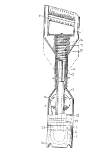
The tying machine illustrated in Figs. 1 and 2 includes a
handle 1 which merges with an outer tubular part 2 that can
move telescopically in relation to an inner concentrical tube
3 which, in turn, merges with or is connected to a supportive
device 4. The machine is intended to be supported during a
working operation by the reinforcement rods 5, 6 that are to
be tied or lashed together, i.e. by twisting together the
legs of a wire tie that embraces the mutual point of inter-
' section of the rods.
v The machine is provided to this end with two pivotal jaws 7
which are normally open and which when the supportive device
4 rests on the rods 5, 6 can be displaced downwards in
relation to said supportive device and closed together on the
CA 02228309 l998-0l-30
W O 97/07304 PCT/SE96/01017
underside of the rods. This enables a tying wire 8 to be
withdrawn from a storage reel 9 and fed through a passageway
in the jaws 7. The jaws can then be reopened, moved upwards
and then re-closed on the upper side of the rods. The wire
is therewith cut and the jaws are then able to rotate so as
to twist together the legs of the generally U-shaped wire tie
thus formed.
Displacement of the jaws 7 and closing of the jaws on the
underside of the rods 5, 6 is effected by depressing the
handle 1 and the telescopic tube 2 in relation to the
telescopic tube 3 carrying the supportive device 4; see the
chain line position of the handle 1 in Fig. 2. This movement
results in compression of a spring 10 provided in the handle.
lS When the down-pressing force on the handle 1 is released, the
spring 10 will return the handle to the position shown in
full lines, and therewith also lift the jaws 7 to a position
above the rods S, 6 in which the jaws can be re-closed.
The aforedescribed function is achieved through the medium
of a jaw holder device 23 which is connected to a generally
U-shaped operating handgrip 11 in the handle 1, via an
operating rod 12. The rod 12 is thus lifted when the operat-
ing handgrip 11 is pressed or pulled up. The operating rod
12 is tubular and acco~odates a pull rod or pull line 13 as
shown in Fig. 4A, for instance. The rod or line 13 accompa-
nies movements of the rod 12, although with a certain degree
of freedom in relation thereto. The rod 12 is provided to
this end with slots 14 in which guide shoulders or pins 15
on the pull rod 13 run.
The supportive device 4 includes two pairs of diagonally
opposed recesses 16, of which a pair of recesses coact with
the uppermost reinforcement rod 16 in each rod tying opera-
tion so as to provide precise positioning of the machine inrelation to the intersection points of the rods S, 6.
CA 02228309 l998-0l-30
W O 97/07304 PCT/SE96/01017
An inventive machine and its method of operation will now be
described in more detail with reference to the embodiment
illustrated in Figs. 3-6.
The machine is shown in Fig. 3 in a starting position with
the supportive device 4 resting on the reinforcement rod 6
at its point of intersection with the underlying reinforce-
ment rod 5, outwardly of the jaws 7. The jaws 7, which are
pivotal about respective pivot points 17, are held open by
two flanges 18, 19 provided on the pull rod 13 that runs
through the tubular operating rod 12 and coacts with a
projection 20 on respective jaws 7. The pull rod 13 is held
in the illustrated position relative to the operating rod 12
by means of a spring 21.
The reference numeral 22 identifies an electric motor which
is driven for rotation of the jaw holder means 23 by means
of a battery (not shown) mounted in the handle. The overlying
fixed part 24 includes a passageway 25 in which wire 8 taken
from the reel 9 is advanced through the medium of a guide 26.
The fixed part 24 carries a laterally movable cutter 27 which
is actuated by a ~-~ ;ng surface 28 on the operating rod 12
as the rod is lifted, so as to cut through the wire 8 located
in the passageway 25. A cutter return spring is illustrated
schematically at 32.
Fig. 4 illustrates the position reached when the jaws 7 and
associated devices have been moved downwards in relation to
the supportive device 4 and the reinforcement rods 5 and 6
as a result of pressing down the handle 1, until the ends of
the jaws are located beneath the rods 5 and 6. The rods 5 and
6 therewith coact with the flange 18 to press the pull rod
13 upwards. The spring 21 has herewith been compressed and
the jaws 7 closed as a result of the coaction of the flanges
18 and 19 with the projection 20 on respective jaws.
CA 02228309 1998-01-30
WO 97/07304 PCT/SE96/01017
An electric motor 29 has therewith been activated and taken
wire 8 from the reel 9 and fed the wire through a passageway
30 provided in the jaws 7. Guiding of the wire from the end
of one jaw to the end of the other is facilitated by a
conically narrowing guide surface 31 provided on the end of
said second jaw.
As will be seen from Fig. 4A, the guide pins 15 on the pull
rod have moved in the slots 14 in the operating rod towards
the upper ends of said slots during upward movement of the
pull rod 13 in relation to said rod 12.
Subse~uent to having fed the wire 8 through the jaws 7, the
down-pressing force on the handle 1 is removed and the spring
10 therewith restores the jaws 7 and associated devices to
their respective starting positions; see Fig. 5. The force
exerted by the reinforcement rods 5, 6 on the flange 18 will
therewith also cease, therewith enabling the spring 21 to
force-out the pull rod 13, whereupon the jaws 7 are reopened
as a result of the coaction between their projections 20 and
the flanges 18 and 19. The wire 8 thus forms an open tie
around the reinforcement rods 5, 6.
As shown in Fig. 5A, the guide pins 15 on the pull rod 13
will therewith be located at the bottom ends of the slots 14
in the hollow rod 12.
In this position, the operating handgrip 11 is pressed up so
as to lift the rod 12 and its ~-~ ;ng surface 28; see Fig.
6. The camming surface will herewith force the cutter 27 to
move laterally, so as to cut the wire 8 and compress the
return spring 32. When the guide pins 15 are located at the
bottom of respective slots 14, the pull rod 13 will also
accompany upward movement of the rod 12 and therewith lift
the flanges 18 and 19 for renewed closure of the jaws 7,
while compressing the spring 21. The force at which the jaws
7 are pressed together is controlled by the force at which
CA 02228309 1998-01-30
W O 97/07304 PCT/SE96/01017
the handgrip 11 is pressed upwards, therewith enabling the
jaws 7 to firmly press the legs of the wire tie between their
end surfaces.
The motor 22 is started in this position and causes the jaw
holder means 23 to rotate through a predetermined number of
turns, e.g. through the medium of gearing 33, therewith
causing the jaws to twist together the legs of the wire tie
on the upper side of the reinforcement rods. The rods are
therewith pressed into firm abul ent with one another at the
point of intersection of the rods. The quality of the tie or
lashing can be improved by causing the jaws to approach the
reinforcement rods during the tying moment.
When the jaws 7 have been rotated sufficiently to obtain
effective lashing of the rods, the operating handgrip 11 is
fully released, wherewith the spring 21 presses the pull rod
13 and the flanges 18 and 19 downwards. This results in
reopening of the jaws in preparation for the next tying or
lashing operation. The operating rod 12 and its c~ ing
surface 28 also participate in the downward movement of the
pull rod 13, therewith enabling the return spring 32 to
return the cutter 27, so that a new wire 8 can be fed down
in the passageway 25.
Fig. 7 illustrates the machine provided with an alternative
embodiment of the supportive device 4. In the case of this
embodiment, the supportive device has the form of a rigid rod
34 provided with seatings 35 for the reinforcement rods 5,
6. The supportive device is attached to the inner tube 3 by
means of stays 36. This embodiment enables the workman to
position the machine precisely in its correct position in
relation to the rod intersection points, since the workman's
view is not obstructed by the supportive device.
Although the invention has been described above with refer-
ence to exemplifying embodiments illustrated in the accompa-
-
CA 02228309 1998-01-30
W O 97/07304 PCT/SE96/01017
nying drawings, it will be understood that modifications and
changes can be made in several respects within the scope of
the following Claims. For instance, the jaw pivoting mecha-
nism can be modified, both with respect to how the rotational
movements are transferred to the jaws, and with respect to
the design of the operating handgrip. The positions of the
various springs can also be varied while retaining the
aforedescribed function. Although the machine has been
described with reference to lashing or tying reinforcement
rods, the machine can also be used for a number of other
purposes, as indicated in the introductory paragraph.
_