Note: Descriptions are shown in the official language in which they were submitted.
CA 02228477 1998-02-02
W O 97/06336 PCTrUS96/12816
DOWN ~OLE PRESS~RE INTENSI~IER AND DRI~LING
ASSEMBLY AND ~ET~OD
Cross Re~erence To Related Applications
This application claims the bene~it o~ the
priority date o~ U.S. Provisional Application
60/001,859, ~iled August 3, 1995, entitled "DOWN
HOLE PRESSURE INTENSIFIER AND DRIL~ING ASSEM~3~Y",
and also claims the bene~it o~ the priority date
o~ U.S. Provisional Patent Application 60/010,849,
~iled January 30, 1996, entitled "DOWN HOLE
PRESSURE INTENSIFIER AND DRILLING ASSEMBLY AND
METHOD".
lS
Backqround o~ the Invention
a) ~ield of the Invention
The present invention relates to a method and
apparatus ~or drilling in an earth strata, and
particularly ~or drilling oil and gas wells. More
speci~ically, the present invention relates to a
pressure intensi~ier and drilling assembly having
a down hole pump to provide ror jet assisted
drilling.
b) Background Art
In the drilling o~ deep holes, such as in
drilling oil and gas wells, it has long been
recognized that the rate o~ penetration can
sometimes be substantially enhanced by using a
30 high pressure (15,000 PSI or greater) jet assisted
driIling, particularly where the rock strata is
harder or more di~icult to drill. One prior art
method to accomplish this is to provide the drill
stem with an inner concentric tube in which very
SUBSllTUTE SHEEl (RULE ~r~.3
CA 02228477 1998-02-02
WO97/06336 PCT~S96/12816
high pressure fluid is transmitted ~rom a sur~ace
location downwardly through the inner tube to ~low
out one or more high pressure jet openings. Then
the drill mud at lower pressure is transmitted
through the annular passageway between the drill
casing and the inner high pressure tube, with the
drill mud ~lushing out the debris in the hole
being drilled and carrying this to the sur~ace in
an upward ~low path between the drill casing and
the wall o~ the hole being drilled.
Because o~ the problems related to directing
the ultra high pressure ~luid in the center pipe
over long distances which occur when deep wells
are being drilled, it has been proposed in the
past to use the drill ~luid itsel~ to drive a
pressure intensi~ier pump to provide the very high
pressure ~luid ~or the jet cutting at the location
o~ the lower end o~ the drill stem. This approach
also involves a number o~ technical challenges,
with regard to designing and arrange o~ the
apparatus to accomplish this task e~iciently and
reliably, and also have the apparatus ~it within
the con~ined space o~ the drill hole.
The present invention is directed toward
2s providing such a drill assembly where jet assisted
drilling is accomplished by a pressure intensi~ier
at a down hole location, and providing the drill
assembly with a combination o~ ~eatures which
e~ectively address the problems such as those
noted above. Also the present invention can be
used ~or other down hole applications, such as
scouring, per~orating, and stimulating oil and gas
SUBSTITUTE SHEET (RULE 26)
CA 02228477 1998-02-02
W O 97/06336 PCTAJS96/12816
wells, or used in other environments having
~imilar problems.
SUBSTrrUrE SHEEl (RUl~ 26)
CA 02228477 1998-02-02
WO 97/06336 PCTAUS96/12816
Summarv o~ the Invention
In the apparatus and method o~ the present
invention, there is a pump and drilling assembly
~or drilling into an earth ~ormation. This
assembly comprises an elongate housing structure
having a longitll~; n~ 1 axis, an upstream end
adapted to be connected to a drill string and to
receive drill ~luid there~rom, and also a
downstream end. The housing comprises a tubular
outer housing and an inner housing positioned
within the outer housing.
There is a drill bit assembly connected to
the downstream end o~ the housing structure. This
drill bit assembly has a high pressure ~luid jet
discharge means.
There is a pressure intensi~ier means
positioned in the inner housing. This pressure
intensi~ier comprises low pressure piston means
mounted ~or reciprocatlng motion in low pressure
chamber means within the inner housing. There is
also high pressure piston means connected to the
low pressure piston means and mounted ~or
reciprocating motion in high pressure chamber
~5 means within the inner housing.
There is a longltudinally extending main
~luid passageway means having an inlet end at an
upstream location to receive ~luid ~low o~ the
drill fluid ~rom the drill stem, and an outlet end
at a downstream location At least a portion o~
the main ~luid passageway means is adjacent to the
pressure intensi~ier means and positioned between
SUBSTITUTE SHEET ~ULE 26)
CA 02228477 1998-02-02
W O 97/06336 PCT~US96/12816
the inner housing and the outer housing. The main
~luid passageway means has an upstream passageway
portion and a downstream passageway portion.
A valve section means is positioned in the
housing structure between the upstream and
downstream ends. The valve section means
comprises a control valve means to receive ~luid
~low ~rom the upstream passageway portion and
selectively direct the ~luid ~low to the low
pressure chamber means to cause the low pressure
piston means to reciprocate and cause the high
pressure piston means to reciprocate. The control
valve means directs ~luid ~rom the low pressure
chamber means to the downstream passageway
portion.
There is provided pressure intensi~ier valve
and passageway means arranged to direct low
pressure drill ~luid into the high pressure
chamber means and to direct higher pressure drill
~luid ~rom the high pressure chamber means to the
high pressure ~luid jet discharge means.
In the pre~erred ~orm, the assembly comprises
a selector valve means operatively connected
between the upstream passageway portion and the
downstream passageway portion o~ the main ~luid
passageway means. The selector valve means has a
~irst position where the drill ~luid is permitted
to pass ~rom the upstream passageway portion o~
the main ~luid passageway means to the downstream
portion o~ the main ~luid passageway means in a
path by-passing the pressure intensi~ier means.
The selector valve means also has a second
SUBSTITUI E SHEET (RULE 26)
CA 02228477 1998-02-02
W O 97/06336 PCTAJS96/12816
position where drill ~luid ~rom the upper
passageway portion is caused to ~low through the
control valve means and thence back to the
downstream passageway portion to cause the
pressure intensi~ier means to operate.
The selector valve means is responsive to
volumetric ~low o~ drill ~luid through the
upstream passageway portion to move between its
~irst and second position The selector valve
means comprises means to de~ine a by-pass
passageway leading ~rom the upstream passageway
portion to the downstream passayeway portion, and
a selector valve element having a ~irst position
where the by-pass passageway is open, and a second
position closing the by-pass passageway. Spring
means urges the selective valve element toward its
~irst open position, and the valve element is
responsive to volumetric ~low o~ the drill ~luid
~rom the upstream passageway portion to be urged
against the spring means to move the selector
valve element to the second position.
In two embodiments o~ the selector valve
means there is a pressure relie~ mechanism
responsive to a pressure in the drill ~luid ~rom
the upstream passageway portion higher than a
predetermined level to open the pressure relie~
mechanism to permit ~low ~rom the upstream
passageway portion to the downstream passageway
portion.
In the con~iguration o~ the pressure
intensi~ier means,~the low pressure piston means
comprises ~irst and second low pressure pistons,
SUBSTITUTE SHEEl (RULE 26)
CA 02228477 1998-02-02
W O 97/06336 PCT~US96/12816
positioned in ~irst and second low pressure
chamber sections, respectively, with each low
pressure piston separating its related chamber
section into ~irst and second chamber section
portions. The valve section is positioned
adjacent .to the low pressure chamber means and has
a ~irst valve passageway leading ~rom the control
valve means to one o~ the ~irst chamber section
portions and a second valve passageway leading to
one o~ said second chamber section portions. The
control valve is arranged to direct ~luid ~rom the
upstream passageway portion alternately to the
~irst and second valve passageways, and to
withdraw ~luid ~rom the second and ~irst chamber
section portions alternately.
In a pre~erred con~iguration, the valve
section comprises a valve section houslng
positioned between the ~irst and second low
pressure pistons which are interconnected by a
piston rod extending through the valve section
housing. The piston rod is mounted in the valve
section housing ~or reciprocating movement in
sealing relationship with the valve section
housing. The ~irst valve passageway leads ~rom
the control valve means to one side o~ the valve
section housing to cnmmnn;cate with one o~ ~irst
chamber section portions, and the second valve
passageway leads ~rom the control valve to an
opposite side o~ the valve section housing to
cnmmlln;cate with the one o~ said second chamber
section portions.
,.
SUBSTrrUTE SHEEl (RULE 26)
CA 02228477 1998-02-02
W O 97/06336 PCT~US96/12816
The piston rod has ~irst rod passageway means
extending longitll~; n~ ~ ly and openlng to both o~
the ~irst chamber section portions. There is also
a second rod passageway means extending
longitudinally in the piston rod and opening to
both o~ the second chamber section portions. In
the pre~erred ~orm, the piston rod comprises a
tubular inner rod member and a tubular outer rod
member The ~irst rod passageway means is a
passageway within the inner rod member, and the
second rod passageway means is an annular
passageway between the inner rod member and the
outer rod member.
In the con~iguration shown herein, the high
pressure piston means comprises two high pressure
pistons. The two high pressure pistons, the two
low pressure pistons, and the piston rod comprise
a piston assembly. There is tension rod means
extending through the piston rod to the two high
pressure pistons. There are means interconnecting
with the ends o~ the tension rod means to place a
tension load on the tension rod means to apply a
compressive load through the high pressure pistons
and into the piston rod.
In a pre~erred embodiment, there is at least
a third low pressure piston positioned in a third
low pressure chamber section The third low
pressure piston is connected by a piston rod
section to the second low pressure piston The
piston rod section has ~irst and second additional
rod passageway means interconnecting with the
~irst and second rod passageway means o~ the
SUBSTlTUrE SHEEl (RULE 26)
CA 02228477 1998-02-02
W O 97/06336 PCTAUS96/12816
piston rods, to cause the ~irst and second chamber
section portions o~ the third piston to
commlln~cate with the ~irst and second valve
passageways.
The valve section ~urther comprises pilot
valve means operatively connected to the control
valve means to direct ~luid pressure against
pressure control sur~ace m~nq o~ the control
valve means to cause the control valve m~nC to
move between the ~irst and second positions. The
pilot valve means has actuating members positioned
at ~irst and second chamber section portions on
opposite sides o~ the valve housing. Each o~ the
actuating members is responsive to operative
engagement o~ an adjacent one o~ the low pressure
piston in a manner that when the low pressure
piston comes into operative engagement with its
related actuating member, the pilot valve m~n.q
move to its other position. This causes the pilot
valve means to move the control valve means ~rom
one o~ its ~irst and second positions to the other
o~ its ~irst and second positions
The actuating members and the pilot valve
means are arranged relative to the two low
pressure piston in a manner that when either o~
the two low pressure piston engages one o~ the
actuating members to shi~t the pilot valve means,
the low pressure piston has not come into
engagement with the valve section housing.
At least one o~ the upstream passageway
portion and the downstream passageway portion o~
the main ~luid passageway means comprlses an
SUBSTITUTE SHEEr (RUlE 26)
CA 02228477 1998-02-02
W O 97/06336 PCTAJS96/12816
- 10
annular passageway portion de~ined by the outer
housing and the inner housing. The valve section
housing has an outer housing portion blocking said
annular passageway. In the pre~erred ~orm, both
o~ the upstream passageway portion and the
downstream passageway portion o~ the main ~luid
passageway means comprise an annular passageway,
with the valve housing having an outer housing
portion separating the two annular passageways
~rom one another.
The present invention ~urther comprises
~ilter means which has a ~irst ~ilter sur~ace
located adjacent to the upstream passageway
portion so as to be in contact with drill ~luid in
the upstream passageway portion. The ~ilter means
has a second sur~ace adjacent to a ~ilter chamber.
The ~ilter means is arranged so that drill ~luid
~lowing into the inlet end o~ the main ~luid
passageway means has portion thereo~ directed
through the ~ilter means into the ~ilter chamber.
The pressure intensi~ier valve and passageway
means comprises inlet passageway means leading
~rom the ~ilter chamber to inlet means o~ the high
pressure piston means. Thus ~iltered drill ~luid
passes into the high pressure chamber means and is
delivered to the high pressure jet discharge
means.
Also, the control valve means has control
~luid passageway means leading ~rom the ~ilter
chamber to pressure operating sur~ace means o~ the
control valve means.
SUBSTITUTE SHEEl (RULE 26)
CA 02228477 1998-02-02
W O 97/06336 PCTrUS96/12816
- 11 -
Further, in a pre~erred ~orm, the control
valve passageway means interconnecting the control
valve passageway means with the ~ilter chamber
connects with the pilot valve means, and the pilot
S valve me~nq interconnects with the pressure
operating-sur~ace means o~ the control valve. The
control valve means and the pilot valve means have
discharge passageway means leading to a location
outside o~ the outer housing, so that the drill
~luid ~rom the ~ilter chamber that is directed to
the control valve means and the pilot valve means
is discharged to a location outside o~ the outer
housing.
In a pre~erred con~iguration, the ~ilter
means comprises a planar ~ilter screen means
having a substantial alignment component parallel
to an adjacent ~low path o~ drill ~luid passing
through the upstream passageway portion. This is
accomplished so that the drill mud in the upstream
passageway portion has a substantial ~low path
component parallel to the ~ilter screen means, so
that the drill ~luid passing adjacent to the
~ilter screen means and through the upstream
passageway portion removes ~iltered particles ~rom
the ~ilter screen means. In a speci~ic pre~erred
con~iguration, the portion o~ the upstream
passageway portion adjacent to the ~ilter screen
means is an annular passageway portion, and the
~ilter screen means extends in a curved
con~iguration inside o~ the annular passageway
portion
SUBST~UTE SHEFI (RULE 26)
CA 02228477 1998-02-02
W O 97/06336 PCTAJS96/12816
- 12 -
Also, there is a second ~ilter means
positioned upstream o~ the ~ilter means. The
second ~ilter means is a more coarse ~ilter means
and the ~ilter means is a ~iner ~ilter means.
S In a pre~erred con~iguration o~ the control
valve means, there is a valve housing having a
longitudinal axis and de~ining chamber means
comprising an inlet ~irst chamber section to
receive ~luid ~low ~rom the upstream passageway
portion, and an outlet second chamber section to
deliver ~luid to the downstream passageway
portion.
There is a longitudinally aligned valve
element mounted ~or reciprocating movement in the
chamber means.
The valve housing has at the ~irst chamber
section a ~irst ~luid inlet port and two ~irst
~luid outlet ports on opposite sides o~ the ~irst
~luid inlet port. The ~irst ~luid inlet port has
a predetermined axial ~im~n~icn~
The valve element has a ~irst spool mounted
in the ~irst chamber section ~or reciprocating
movement across the first ~luid inlet port The
~irst spool member has an axial ~;m~n~ion less
than the axial ~;m~n~ion o~ the ~irst inlet port
ln a manner that when the ~irst spool element is
centrally positioned relative to the ~irst inlet
port, there is ~luid ~low ~rom the ~irst inlet
port to both o~ said ~irst outlet ports.
The valve housing has at the second chamber a
second ~luid outleE port and two second ~luid
inlet ports on opposite sides o~ the second ~luid
SUBSTITUTE SHEET (RULE 26)
CA 02228477 1998-02-02
W O 97/06336 PCT~US96/12816
outlet port. The second ~luid outlet port has a
predetermined axial ~;m~n~ion.
There is a second spool element mounted ~or
reciprocating motion in the second chamber
section. The second spool element has an axial
~;m~nqion less than the axial ~;m~n~qion o~ the
second outlet port, in a manner that when the
second spool element is centered in the second
outlet port, the second outlet port commnn;cates
with both the second inlet ports.
The e~ect o~ this is that each spool element
has an intermediate position where ~luid ~low ~rom
the ~irst inlet port is divided to the ~irst
outlet ports, and ~luid ~low ~rom the second inlet
ports ~lows simultaneously through the second
outlet ports.
In a pre~erred ~orm, each o~ the ~irst inlet
port and second outlet port has axial end portions
having a transverse ~;m~nqion which increases in a
direction toward a center portion o~ the ~irst
inlet port and the second outlet port.
There is a high pressure downstream
passageway leading ~rom the high pressure chamber
means to the high pressure ~luid jet discharye
means, this high pressure downstream passageway
having check valve means positioned therein. This
prevents reverse ~low ~rom entering into the high
pressure ~luid jet discharge means. Also, the
high pressure downstream passageway has an
additional ~ilter to prevent particles or debris
~lowing into the high pressure downstream
SUBSTITUT E SHEEI (RULE 26)
CA 02228477 1998-02-02
W O 97/06336 PCTAJS96/12816
passageway and through the high pressure ~luid jet ,~
discharge means.
Also, in the assembly of the present
invention, there is a force transmitting means
positioned at one of a downstream end and an
upstream end of the inner housing, and arranged to
transmit a compression load along said inner
housing, and to react said load into an adjacent
one of a downstream end portion and an upstream
end portlon of the outer housing. Thus, the
compression load is reacted in the inner housing
to the other end portion of the inner housing and
into the other end portion of the outer housing.
The pressure intensifier means comprises a
pressure intensifier housing defining the low
pressure means and the high pressure means. The
pressure intensi~ier housing comprises a portion
o~ the inner housing, with other components of the
inner housing being axially aligned with the
pressure intensi~ier housing. Thus, the ~orce
transmitting means places the pressure intensi~ier
housing and the other components axially aligned
therewith into compressive loading. In a
preferred form, the force transmitting means
comprises a mounting block engaging the outer
housing, and a bearing member engaging an adjacent
portion of the inner housing The force
transmitting means comprises axially adjustable
force transmitting means which can be moved in an
axial direction to press against the bearing
member ~rom the mounting block and thus impart the
compression load to the lnner housing
SUBSTITUl E SHEET (RULE 26)
CA 02228477 1998-02-02
W O 97/06336 PCTAUS96/12816
In a pre~erred con~iguration, the mounting
block comprises an annular block member, and the
bearing member i5 an annular bearing member. The
block member and the bearing member de~ine a
portion o~ a through passageway through which
drill ~luid can pass.
In the pre~erred ~orm, the ~orce transmitting
means is located at the downstream end portions o~
the inner housing and outer housing. The drill
bit assembly is removably mounted at the
downstream end o~ the assembly. The adjustable
~orce transmitting means has adjustable head means
at a downstream location in the ~orce transmitting
means. Thus, the operating head means are
accessible ~rom a downstream location with the
drill bit assembly removed.
In a speci~ic con~iguration, the adjustable
~orce transmitting means comprises a plurality o~
bolt means mounted in the mounting block. The
boat means have downstream positioned bolt head
means which can be engaged to move the bolt means
axially against the bearing member.
In the method o~ the present invention, the
drill bit assembly is provided as described above
The drill ~luid passes into the main ~luid
passageway means, and in the operating mode is
directed through the control valve to the pressure
intensi~ier means to pressurize a portion o~ the
drill ~luid to a very high pressure and direct
this to the jet discharge nozzle o~ the drill bit
assembly To by-pass the pressure intensi~ier
means, the ~luid pressure in the upstream
SUBSTlTUrE SHEEI (RULE 26)
CA 02228477 1998-02-02
W O 97/06336 PCTAJS96/12816
- 16 -
passageway portion i9 lowered to cause the L
selector to move to its bypass position to direct
the ~low ~rom the upstream passageway portion
directly into the downstream passageway portion to
5 ~low to the drill bit assembly. The drill ~luid
that passes through the low pressure chamber or
which passes directly ~rom the upstream passageway
portion to the downstream passageway portion ~lows
to the drill bit assembly to pass into the hole
10 being drilled to ~lush debris ~rom the hole being
drilled
Other ~eatures will become apparent ~rom the
~ollowing detailed description
SUBSTITUTE SHEEl (RULE 26)
CA 02228477 1998-02-02
W O 97/06336 PCT~US96/12816
Brie~ Description o~ the Drawinqs
Figure 1 is a semi-schematic longitudinal
sectional view o~ the ~irst embodiment o~ the
present invention;
Figure lA is a view similar to Figure 1
showing a second embodiment, but only showing the
central portion o~ the apparatus;
Figure lB is a third embodiment, and as in
Figure lA only shows the central portion thereo~;
Figure lC is a simpli~ied ~low circuit
diagram o~ the main components o~ the present
invention;
Figures 2 through 5 are semi-schematic
drawings, which show in sequence the operating
cycle o~ the present invention, these showing only
the central portion o~ the apparatus o~ the second
embodiment o~ Figure lA;
Figures 6A and 6B are longitudinal views,
partly in section, o~ the selector valve in two
di~erent operating modes;
Figures 7A and 7B are semi-schematic drawings
showing a ~irst modi~ied version o~ a selector
valve in two di~erent operating modes;
Figures 8A, 8B and 8C are three semi-
schematic drawings showing a second modi~ied
version o~ the selector valve in three di~erent
operating modes;
Figure 9 is a semi-schematic view o~ a third
modl~ied version o~ the selector valve;
SUBSTITUTE SHEEr (RULE 26)
CA 02228477 1998-02-02
W O 97/06336 PCTAJS96/12816
- 18 -
Figure 10 is a semi-schematic longitl1~in~
view showing the trigyer valve somewhat
schematically;
Figure 11 is another semi-schematic view of
only the trigger valve and the control valve;
Figure 12A is a longitudinal sectional view
showing somewhat schematically the valve element
and the housing structure o~ the control valve;
Figure 12B is a longitudinal sectional view
showing a portion o~ the control valve where one
o~ the valve spools is passing by the center port
of one side of the valve;
Figure 12C is a view similar to Figure 12B,
showing the valve portion o~ Figure 13B, but with
the central port and spool being worn away to some
extent;
Figure 13A is a longitl~;n~l sectional view
o~ one version o~ a ~ine mesh filter at the
upstream end of the assembly;
Figure 13B is a sectional view taken at line
13B-13B o~ Figure 13A;
Figure 14A is a somewhat schematic
longit-1~; n~ 1 sectional view of one version of the
piston assembly o~ the present invention;
Figure 14B is a view similar to Figure 14A
which shows a modi~ied version o~ the piston
assembly;
Figures 15A, 1sB and 15C are longitn~i n~
sectional views showing, respectively, an end
por~ion, a middle portion, and an opposite end
portion o~ the apparatus o~ the present invention,
this being shown in more detail;
SUBSTlTUrE SHEEl (RUl F 26)
CA 02228477 1998-02-02
W O 97/06336 PCTtUS96tl2816
- 19
Figures 16, 17, 18 and 19 are sectional views
taken.at lines 16, 17, 18, and 19 o~ Figures lSA
through 15C.
SUBSTITUTE SHEET (RULE 26)
CA 02228477 1998-02-02
W O 97/06336 PCT~US96/12816
- 20 -
~escription o~ the Pre~erred Embodiment
A. General Descri~tion o~ the Present Inven~ion
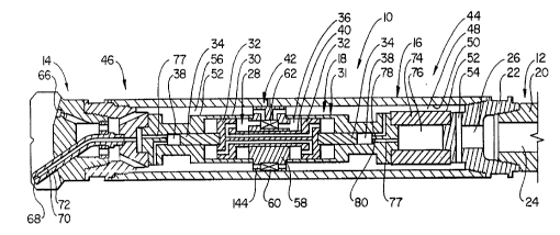
The pump and drilling assembly 10 o~ the
present invention is shown somewhat schematically
in Figure 1. This assembly 10 comprises a drill
stem (only the lower end o~ which is shown at 12
in Figure 1), a drill bit assembly 14, an outer
tubular housing 16 extending between and
connecting the drill stem 12 with the drill bit
assembly 14, and a pressure intensi~ier section or
system 18 positioned in the housing 16.
The overall con~iguration o~ the pump and
drilling assembly 10 is that o~ an elongate
cylinder o~ relatively small diameter. The drill
stem 12 delivers drilling mud into the pressure
intensi~ier system 18. The intensi~ier section 18
has an operating mode and a non-operating mode.
In the operating mode, the intensi~ier section 18
receives the drilling mud at a moderately high
pressure (e.g. 3,000 PSI) and utilizes this mud to
raise the pressure o~ a relatively small portion
o~ this drilling mud to a relatively high pressure
(e.g. 20.000 to 50,000 PSI). This very high
pressure drilling mud is in turn delivered to the
drill bit assembly to be emit~ed as very high
pressure ~luid jets that assist in the drilling
operation. The r~m~i ni ng larger portion o~ the
mud is delivered to the drill bit assembly and is
discharged through a ~lush nozzle or nozzles to
per~orm its usual ~unction or ~lushing out the
various rock ~ragments and debris that have been
SUBSTlTUrE SHEEl (RULE 26)
CA 02228477 1998-02-02
W O 97/06336 PCT~US96/12816
removed in the drilling operation. These
~ragments and debris are carried by the mud
upwardly in the annular space between the housing
16 and the bore hole and ~urther upwardly around
the drill stem to the sur~ace.
In the non-operating mode o~ the intensi~ier
section 18, the intensii~ier section 18 i3 by-
passed. The drilling mud ~lows out the drill bit
assembly 14 and upwardly through the annular space
between the bore hole and the drill stem 12.
The drill stem 12 is, or may be, o~
conventional design, and as shown herein the lower
end 20 o~ the bottom end o~ the lowermost section
o~ the drill stem 12 is threadedly connected to a
stem adapter 22. The drill stem has a central
through ~low passage 24 which leads to a passage
26 in the adapter 22 to deliver the drilling mud
into the upper end o~ the intensi~ier section 18.
The drill bit assembly 14 is, or may be, o~
conventional design, and would commonly have
cutters (not shown ~or convenience o~
illustration) on its operating ~ace. The entire
drill stem 12 is rotated to cause the cutters to
travel a rotary path to engage and remove the rock
or other material that is being drilled. In the
non-operating mode o~ the intensi~ier section,
these cutters operate unassisted by the ultra-high
pressure cutting jets. In the operating mode o~
the intensi~ier section 18, the ultra-high
pressure jets assist the cutters to enhance the
drilling operation
SUBSTITUTE SHEET (RULE 26)
CA 02228477 1998-02-02
WO 97/06336 PCT~US96/12816
In the ~ollowing description, the term
"upper" or "upward" shall denote proximity to, or
a direction toward the stem adapter 22 and drill
stem 12, while the term "lower" or "downward"
shall denote a direction toward or proximity to
the drill bit assembly 14. Also, the term
"upstream" shall denote proximity to the upper end
o~ the assembly 10, while the term "downstream"
shall denote proximity to the drill bit assembly
14.
The design o~ the present invention uni~uely
solves a number o~ critical challenges or
problems. It must be recognized that in many
drilling operations, the drill stem 12 could
extend several miles into the earth strata, and
the remoteness o~ the pumping and drilling
assembly 10 ~rom the above ground control location
magni~ies the usual operating problems. First,
there is the problem o~ reliability and
durability. I~ the pressure intensi~ier 18 in the
drilling assembly 10 becomes damaged or
non~unctional so that it must be withdrawn up to
the sur~ace location ~or repair, this can be
extremely costly.
Another signi~icant problem is that the
drilling mud which ls commonly used in a drilling
operation (this drilling mud usually comprising a
carrier ~luid with small particles suspended
therein) is highly abrasive As will be disclosed
later in this description, in addition to
per~orming its usual ~unction o~ clearing out the
debris that is being drilled and raising it to the
SUBSTITUTE SHEEl (RULE 26)
CA 02228477 1998-02-02
W O 97/06336 PCT~US96/12816
sur~ace, the drilling mud i9 used in the present
invention not only as the ~luid that ~orms the
ultra-high pressure jet, but is also used as the
lower pressure operating ~luid in the high
pressure intensi~ier section. This results in a
number o~ challenges in designing the systems to
m;n~m; ze the e~ect o~ the abrasion that could
result ~rom the drill mud.
Yet another consideration is the
con~iguration and sizing o~ the assembly 10. For
the ultra-high pressure liquid jet cutting to be
e~ective, it is necessary not only to raise the
pressure to a relatively high level (e.g. 20,000
to 50,000 PSI), but also to provide the ultra-high
pressure jet cutting ~luid at a su~iciently high
volumetric rate.
The m~nn~r in which the present invention
solves these various problems will be discussed in
more detail as we continue through the description
o~ the invention.
With ~urther re~erence to Figure 1, the
pressure intensi~ier section 18 comprises a piston
assembly 28 and a pump housing 30 in which the
piston assembly 28 reciprocates. The piston
assembly 28 comprises a central portion 31
comprising a plurality o~ low pressure pistons 32,
each having a relatively large diameter, and two
ultra-high pressure plungers 34 positioned on
opposite ends o~ the central section 31 comprising
the lower pressure pistons 32. The pump housing
30 has a central larger diameter chamber 36 in
which the larger pistons 32 reciprocate At
SUBSTllUTE SHEFr (RULE 26)
CA 02228477 l998-02-02
W 097/06336 PCT~US96/12816
- 24 -
opposite ends o~ the central chamber 36 are
smaller diameter ultra-high pressure chambers 38
in which the respective plungers 34 reciprocate.
In the schematic drawing o~ Figure 1, there
S are shown only two low pressure pistons 32. The5e
two pistons 32 are connected by a center rod 40.
As will be disclosed later, there can be three or
~our low pressure pistons or more. Where there
are more than two low pressure pistons 32, there
are additional rods or rod sections
interconnecting each adjacent pair o~ low pressure
pistons 32.
Positioned within the outer housing 16 at a
location between the two low pressure pistons 32
is a valve section 42. This valve section 42
separates the assembly 10 into an upstream section
44 and a downstream section 46. In the upstream
section 44, there is an outer annular upstream
passage 48 de~ined by the inner sur~ace SO o~ the
outer tubular housing 16, and the outer sur~ace 52
o~ the pump housing 30. The pressurized drilling
mud received ~rom the drill stem 12 and the stem
adapter 22 i~lows through the passageways 24 and 26
and through a passageway schematically shown at 54
into the annular passageway 48 to ~low to the
valve section 42. The manner in which this ~low
through the passage 54 is ( f~or convenience oi~
illustration) lndicated only schematically in
Figure 1, but will be described more ~ully later
in this text where a ~ilter system and other
components will be~described
SUBSTITUTE SHEEl (RULE 26)
CA 02228477 l998-02-02
W 097/06336 PCTrUS96/12816
- 25 -
The downstream section 46 has (in a manner
similar to the upstream section 44) an annular
passageway 56 de~ined by the downstream inner
surface portion 50 of the outer hou9ing 16 and the
downstream outer surface portion 52 of the pump
housing 30. This downstream annular passageway 56
receives drilling mud from the valve section 42
and delivers this mud in a downstream direction.
The valve section 42 comprises a valve
housing 58 which fits against the inner suri~ace 50
of the outer main housing 16 to form a seal at
this surface 50. Mounted within the valve housing
50 is a selector valve 60 and a control valve 62.
In addition to the valves 60 and 62, there is
mounted in the valve housing 58 a trigger valve 64
(not shown in Figure 1, but shown in other
drawings herein and later described herein) which
operates in response to the back and forth
movement of the piston assembly 28 to cause the
proper shifting of the control valve 62.
It is believed a clearer underst~n~;ng of the
operation of the present invention will be
obtained by referring also to Figure lC which is a
simplified diagram of the main components showing
more clearly the flow patterns in the assembly 10.
As mentioned previously herein, the selector
valve 60 has two operating modes, namely a by-pass
mode and a pumping mode. In the by-pass mode, the
selecror valve 60 permits the flow of drill mud
from the upstream annular passageway 48 through
the outlet passageway 144 of the selector valve 60
directly into the downstream annular passageway 56
L
SUBSTITUTE SHEFr (RULE 26)
CA 02228477 1998-02-02
W O 97/06336 PCT~US96/12816
~rom which the drill mud ~lows into the drill bit
assembly 14. This drill mud then ~lows out the
~lush nozzle or nozzles 66 to per~orm the usual
~unction o~ the drill mud o~ ~lushing the
~ragments and debris from the drill sur~ace o~ the
ground strata and carry these upwardly in the
annular space between the surrounding sur~ace o~
the drill hole and the outer sur~ace o~ the drill
stem 12 and housing 16. There is also one or more
ultra-high pressure discharge nozzles 68, through
which the very ultra-high pressure ~luid ~rom the
intensi~ier section 18 is received in the pumping
mode. However, in this by-pass mode, little or no
~luid is discharged ~rom the one or more high
pressure nozzles 68.
When the selector valve 60 is in the pumping
mode o~ operation, the pressurized drilling mud
~rom the drill stem 12 is directed into sections
o~ the central chamber 36 in an alternating
~ashion (due to the action o~ the control valve
62) to cause the piston assembly 28 to reciprocate
~ack and ~orth This reciprocating motion o~ the
piston assembly 28, causes each o~ the plungers 34
to reciprocate sequentially on an intake stroke
and discharge stroke to supply a portion o~ the
drill ~luid (i.e drill mud) at ultra-high
pressures to ~low to the drill bit assembly 14 to
pass into a passageway 70 de~ined by an ultra-high
pressure discharge tube 72 that in turn delivers
the ultra-high pressure jet through the ultra-high
pressure nozzle or-nozzles 68.
SUBSTITUTE SHEEl (RULE 26)
,
CA 02228477 l998-02-02
W 097/06336 PCT~US96/12816
- 27 -
There is provided at the upstream end o~ the
pumping system 18 an ultra-high pressure
attenuator 74 which receives the outi~low ~rom the
upstream and downstream ultra-high pressure
chambers 3 8. The chamber 76 o~ the attenuator 74
connects ,with both of~ the discharge passageways 77
leading ~rom the high pressure chambers 38 via a
tubing (not shown in Figure 1 but shown and
described later herein) to provide a more constant
ultra-high pressure ~low to the nozzle or nozzles
68. The two ultra-high pressure chambers 38 are
each provided with an inlet check valve 78 and an
outlet check
valve 80 connected to a related outlet tube 77 to
accomplish the proper inlet and outlet ~lows ~rom
each ultra-high pressure chamber 38.
Ag indicated above, there can be three, ~our
or more low pressure pistons 32 to increase the
total ~orce exerted on the piston assembly 28 to
cause its reciprocating motion, without increasing
the diameter of~ the pumping system 18. Figure lA
shows only the pumping section o~ the assembly 10,
with the modi~ication that there are three low
presgure pistons 32 instead of~ two low pressure
pistong 32, as shown in Figure 1 The third low
pressure piston 32 is simply added onto one side
o~ the upstream low pressure piston 32 and there
~s a stationary partition 82 separating the
chamber portions between the two upstream low
pressure pistong 32.
In Figure lB, there is shown another
embodiment o~ the assembly 10 o~ Figure 1, where
SUBSTITUTE SHEEl (RULE 26)
CA 02228477 l998-02-02
WO 97/06336 PCT~US96/12816
- 28 -
there are ~our low pressure pistons 32, two o~ the
pistons 32 being positioned upstream o~ the
central valve section 42 and two o~ these pistons
32 at a downstream location ~rom the valve section
5 42. Another partition 82 iS added on the
downstream side to separate the chamber portions
between the two downstream low pressure pistons
32. Figure lC shows a simpli~ied diagram o~ the
major mechanical components, and their
relationships in the overall ~luid ~low schematic.
It is to be understood that Figures 1, lA, lB
and lC are rather schematic and are intended to
describe the main components o~ the present
invention in a simpli~ied ~orm.
To complete the general description o~ the
overall apparatus, re~erence is now made to
Figures 2, 3, 4 and 5 which are somewhat schematic
and illustrate in sequence one hal~ cycle o~ the
back and ~orth reciprocating motion o~ the piston
20 assembly 28. There will now be a ~urther
description o~ the apparatus, and then the mode o~
operation will be discussed in the ~ollowing
section with ~urther re~erence to Figures 2 - 5. It
should be noted that in Figures 2 through 5, the
25 upstream and downstream locations are reversed
relative to Figures 1, lA, and lB. Accordingly,
the upstream side in Figures 2 through 5 is at the
le~t hand o~ Figures 2- 5, and the downstream side
at the right side of~ Figures 2-5. Also, Figures
2-5 shows ~hree low pressure pistons 32, as
illustrated in Figure lA.
SUBSTITUTE SHEET (RULE 26)
CA 02228477 1998-02-02
W O 97/06336 PCTrUS96/12816
- 29 -
It will be noted that in Figures 2-5 the
control valve 62 has been shown more completely
than in Figure 1 (but still somewhat
schematically). More speci~ically, it can be seen
that the control valve 62 comprises a
reciprocating valve element 84 which comprises a
central piston 86 and end spools 88, each o~ which
is connected by a rod 90 to the central piston 86.
The upstream annular passageway 48 leads into an
upstream inlet port 92, and the downstream annular
passageway 56 leads ~rom a downstream outlet port
94. (The control valve 62 is shown in more detail
in Figures 10, 12A, 12B and 12C, and will be
described more ~ully later herein.)
For convenience o~ description, the three low
pressure pistons 32 will be designated (by reading
le~t to right in Figures 2 through 5) 32a, 32b,
and 32c. Also, the low pressure chamber 36 will
be considered as being separated into three
chamber portions 36a, 36b and 36c, each having
positioned therein a related one o~ the pistons
32a, 32b and 32c, respectively. Further, each
chamber portion 36a, 36b and 36c shall be
considered as having an upstream chamber portion
96a, b and c, respectively, and a downstream
chamber portion 98a, b and c, respectively
With the valve element 84 in the right hand
position as shown in Figure 2, the port 92
connects to a le~t hand chamber portion 96b which
is upstream o~ the low pressure piston 32b. Also,
it will be noted that the outlet port 94 connects
SUBSTITUTE SHEEl (RULE 26)
CA 02228477 1998-02-02
WO 97/06336 PCTAJS96/12816
- 30 -
to a chamber portion 98b which i9 between the
piston 32b and the valve section 42.
It will be noted that each o~ the upstream
chamber portions 96a, 96b and 96c, are
interconnected with one another through a related
port 100a, 100b and 100c, respectively, all o~
which connect to a central passageway 102
extending the length o~ the connecting rod 40.
Thus, it can be recognized that when the drill mud
~rom the upstream section 44 passes through the
annular passageway 48, through the port 92 and
into the chamber portion 96b, it also ~lows into
the port 100b, through the passageway 102 and out
the ports 100a and 100c into the other two chamber
sections 96a and 96c, respectively
In like manner, each piston 32a, b and c has
a second port 104a, 104b and 104c, respectively,
with each o~ these ports being interconnected by
another passageway 106 also extending through the
center rod 40, thus interconnecting the downstream
chamber portions 98a, b and c.
In Figures 2 through 5, ~or convenience o~
illustration, the selector valve 60 is not shown.
On the other hand, the a~orementioned trigger
valve 64 is shown somewhat schematically For
clarity o~ illustration in the Figures, the
components o~ the trigger valve will not be given
numerical designations in Figure 2, but these
numerical designations will be indicated in Figure
The trigger valve 64 comprises a trigger
valve element 108 having two spools 110 and 112
SUBSTITUTE SHEEI (RULE 26)
CA 02228477 l998-02-02
W097/06336 PCT~S96/12816
- 31 -
Extending laterally outwardly ~rom each spool 110
and 112 are ~irst and second trigger ~ingers 114
and 116, with the le~t trigger ~inger 114
extending into the chamber 98b, and the other
trigger ~inger 116 extending into the chamber 96c.
There is a ~luid outlet line 118 which leads ~rom
two ports 120 and 122 positioned at the end
locations o~ travel o~, respectively, the spool
elements llO and 112, respectively and discharges
to a location outside the outer housing 16. The
trigger valve 64 has its valve chamber 123
connecting to either o~ two outlet lines 124 and
126 which connect to ported locations on opposite
sides o~ a central valve chamber 128 o~ the
control valve 62. Also, there is an inlet
passageway 130 which leads ~rom an upstream
location to direct ~iltered drilling mud to a
central inlet port 132 at the middle o~ the
trigger valve chamber 123.
The two outlet check valves 80 are
interconnected with one another through the
passageway 134, and this passageway 134 also
connects to the attenuator 74. The two inlet
check valves 78 connect with one another through a
line 136. The ~low into this line 136 is ~rom the
line 138 that in turn connects to the ~iltered
in~low o~ the upstream drill ~luid.
As will be described later herein, at a
~urther upstream location o~ the inlet 138, there
is provided between the drill stem adapter 22 and
the pumping section 18 a ~iltering section, where
there is a ~irst ~ilter o~ a larger mesh size and
SUBSTlTUrESHEEl (RULE26)
CA 02228477 1998-02-02
WO97/06336 PCT~S96/12816
- 32 -
a second downstream ~ilter having a ~iner mesh
size. (These are shown in Figure 15A and will be
described more ~ully later herein.) The major
part o~ the drill ~luid passes only through the
~irst ~ilter and thence downstream through the
upstream annular passageway 48. The drill ~luid
that passes through the second ~ilter ~lows
through the tube 13 8 to ~low into the upstream
located inlet check valve 78 and also through the
passageway 13 6 to the other inlet check valve 78.
Thus, a portion o~ the twice ~iltered drill ~luid
is part o~ that portion o~ the drill ~luid which
is pressurized to an ultra-high pressure level to
~low through the ultra-high pressure nozzle or
nozzles 68.
Also, the twice ~iltered drill ~luid is
directed into the inlet 140 to ~low to the
passageway 130 to the center port o~ the trigger
valve 64.
To complete this section o~ the overall
general description o~ the assembly 10, re~erence
is now made to Figure 6A and 6B, which illustrate
a presently pre~erred embodiment o~ the selector
valve 60. Figure 6A shows the valve 60 in the by-
pass mode where the drilling mud ~lows through the
upstream annular passageway 48 through the valve
60 and out a passageway 144 leading to the
downstream annular passageway 5 6 Figure 6B shows
the selector valve 60 in its operating mode where
it blocks the outlet passageway 144 In this
position, the main-~low o~ drilling mud is
compelled to ~low through the control valve 62 and
SUBSTITUTE SHEET (RULE 26)
CA 02228477 l998-02-02
WO 97/06336 PCTAJS96/12816
- 33
through the intensi~ier section 18 to cause the
ultra-high pressure drilling ~luid to ~low
outwardly ~rom the jet nozzles 68.
The selector valve 60 comprises a valve
element 146, a positioning spring 148 and a
mounting member 150 that positions the valve
element 146 in a longitudinally aligned position
in the valve chamber 151. The valve element 146
comprises a plug element 152 which is connected to
an elongate cylindrical valve stem 154 slideably
mounted in the mounting member. A spring abutment
member 156 (shown herein as a pair o~ nuts
threaded against each other in locking engagement)
is threaded onto the upstream end o~ the valve
stem 154. The positioning spring 148 is a
compression spring that bears against the
a~orementioned mounting element 150 at one end and
against the abutment member 156 at the other end.
Thus, the valve element 146 is urged by the spring
148 to its by-pass position shown in Figure 6A
where the valve element 146 is spaced away ~rom
the valve seat 158. The mounting member 150
engages the inwardly ~acing sur~ace 160 that
de~ines the valve chamber lS1, and this member 150
has a plurality o~ through openings 162 to permit
the ~low o~ the drill mud through the mounting
member 150.
As indicated previously herein, the selector
valve 60 is responsive to the volumetric ~low rate
30 o~ the drilling mud ~lowing through the drill stem
12. In the by-pass mode, the volumetric ~low of
drill mud is at a su~iciently high pressure so
SUBSTITUTE SHEEl (RULE 26)
CA 02228477 1998-02-02
W O 97/06336 PCTAUS96/12816
that the drill mud is able to per~orm its usual
~unction o~ ~lushing out the ~ragmented rock and
other debris ~rom the end o~ the bore hole and
move the same upwardly in the annular space
between the bore hole and the stem 12. However,
the volumetric ~low rate and pressure i9 not great
enough to overcome the ~orce o~ the positioning
spring 148 and ~orce the valve element 146 into
blocking engagement with the valve seat 158.
To move the selector valve 60 into the
operating mode, the volumetric ~low rate o~ the
drilling mud moving down the drill stem i3 raised
to a higher level so that the volumetric ~low o~
the drill mud against the upstream sur~ace 164 o~
lS the valve plug 152 is su~iciently great to exert
a ~orce on the valve element 146 that overcomes
the ~orce o~ the spring 148 to move the valve plug
152 into the blocking position o~ Figure 6B. As
indicated above, this causes the drilling mud
~lowing through the outer annular passageway 148
to ~low through the pressure intensi~ier section
18.
B. Overall DescriDtion o~ the O~eration o~ the
Present Invention
As indicated previously herein, in addition
to rererring to the speci~ic drawings mentioned in
the ~ollowing text, it would be help~ul to re~er
also to Figure lC which shows the ~low pattern
more clearly.
Re~erence is ~irst made to Figure 1. The
drilling operation~is started in the usual manner
at a sur~ace location where the drill bit assembly
SUBSTITUTE SHEEl (RULE 26)
CA 02228477 1998-02-02
W O 97/06336 PCT~US96/12816
- 35 -
14 is threaded onto the lower end o~ the tubular
housing 16 (containing the pressure intensi~ier
section 18) which in turn is threadedly connected
to the stem adapter 22 that connects to the
lowermost section o~ the drill stem 12.
Initially! the earth strata through which the
drill bit 14 is boring may not be su~iciently
hard to warrant the use o~ the ultra-high pressure
liquid jet that would be emitted ~rom the nozzles
68 Accordingly, in this mode, the drill mud is
pumped into the passageway 24 o~ the drill stem 12
at a volumetric rate that is adequate to ~lush the
~ragmented material ~rom the bore hole and carry
it upwardly around the drill stem 12 to the
sur~ace where the ~ragmented material can be
screened out and the drill mud reused. However,
the volumetric rate is su~iciently low so that
the selector valve 60 r~m~ n~ in its by-pass mode,
as shown in Figure 6A.
In the by-pass mode, the pressure o~ the
drilling mud is su~iciently low so that it either
will not cause the piston assembly 28 to
reciprocate, or simply reciprocate the piston
assembly 28 at such a slow rate that any ~low ~rom
the ultra-high pressure chambers 38 is at a very
low rate (and also at a rather low pressure), so
that the ~low out the ultra-high pressure nozzles
68 has no cutting e~ect (or at most a very
insigni~icant cutting e~ect), with this drill mud
that is ~lowing out the nozzles 68 simply being
added to the rest o~ the drill mud ~lowing out the
~lush nozzles 66 to per~orm the ~lushing
SUBSTITUTE SHEET (RULE 26)
CA 02228477 1998-02-02
Wo97/06336 PCT~S96/12816
operation. During this by-pass mode, the main
~low o~ the drill mud is ~rom the drill stem
through the upstream annular passageway 48,
through the outlet passageway 144 o~ the selector
valve 60, and thence directly into the downstream
annular passageway 56 to ~low outwardly through
the ~lushing nozzles 66.
When the drill bit assembly 14 reaches an
earth strata which is o~ su~icient hardness to
warrant the use o~ the ultra-high pressured jet
assisted cutting, the drill mud pump at the
sur~ace location is caused to operate at a higher
volumetric ~low rate so that the mud ~lowing
through the selector valve 60 moves the selector
valve 60 ~rom the position o~ Figure 6A to the
position o~ Figure 6B to close o~ the ~low
through the selector valve 60. This causes the
entire ~low through the upstream annular
passageway 48 to be directed through the control
valve 62 and into the high pressure intensi~ier
section 18.
Re~erence will now be made to Figures 2-5
which illustrate the pressure intensi~ier section
18 at ~our di~erent stages o~ its operating mode.
As indicated above, in the operating mode the
selector valve 60 moves to its closed position o~
Figure 6B and remains closed until the time that
the volumetric ~low rate o~ the drill mud is
lowered to permit the valve 60 to move back to its
open position ~or the by-pass mode Accordingly,
the selector valve~is not shown ln Figures 2-5.
Rather, the tri~ger valve 64 and the control valve
SUBSTITUTE SHEEl (RULE 26)
CA 02228477 1998-02-02
W O 97/06336 PCT~US96/12816
62 are shown somewhat schematically, but in
su~icient detail to explain the overall mode o~
operation o~ the ultra-high pressure section 18.
(Also, it should be kept in mind that the le~t to
righ~ orientation in Figures 2-5 i9 reversed ~rom
that shown in Figure 1, so that in Figures 2-5 the
upstream end is at the le~t.)
In Figure 2, the piston assembly 28 has just
completed its travel ~rom a right hand position o~
Figure 2 to the le~t hand position shown in Figure
2, and the right ~inger 116 o~ the trigger valve
64 has already been engaged by the right hand
piston 32c to have moved the trigger valve element
108 to its le~t hand position This in turn has
caused the valve element 84 o~ the control valve
62 to move to a right hand position, as shown in
Figure 2.
With reference to Figure 2, with the piston
assembly 28, the control valvè 62 and the trigger
valve 64 in the positions shown in Figure 2, the
piston assembly 28 is now beginning its path o~
travel in a right hand direction It is believed
that it would be help~ul i~ at this point o~ the
description o~ the operation, a distinction is
made between the main ~low o~ drill mud, which is
once ~iltered, and the ~low o~ the drill mud which
is twice ~iltered. As indicated previously
herein, upstream o~ the pressure intensi~ier
section 18 there is a dual ~ilter system, which
will be described later herein.
Stated brie~l~, there is a ~irst ~ilter
through which the drill mud travels to ~low
SUBSTITUTE SHEEl (RULE 26)
CA 02228477 1998-02-02
WO97/06336 PCT~S96/12816
- 38 -
directly into the upstream annular passageway 48.
Then a portion o~ the drill mud that ~lows through
the ~irst ~ilter is redirected through a second
~ilter o~ ~iner mesh size to provide a ~low o~
twice ~iltered drill mud. This twice ~iltered
drill mud is directed into the tube inlet 13 8, and
also through the inlet 140 ~or the tube 130.
The twice ~iltered mud ~lowing into the tube
138 is directed to the inlet check valves 78 ~or
the two high pressure chambers 38. Thus, the ~low
o~ ultra high pressure liquid (i.e. drill mud)
which is discharged ~rom the two outlet check
valves 80 and into the interconnecting line 134
which connects to both outlet check valves 80 is
also twice ~iltered drill mud This line 134 also
connects to the chamber 76 o~ the attenuator 74.
Thus, the ultra high pressure drill mud which
~lows into the ultra high pressure passageway
(indicated at 166) and to the ultra high pressure
20 nozzles 68, is drill mud which has been twice
~iltered.
In addition, the drill mud that ~lows into
the inlet 140 is also twice ~iltered, and this
drill mud is directed into the central port 132 o~
25 the trigger valve 64. This ~low o~ twice ~iltered
drill mud which ~lows into the valve chamber o~
the trigger valve 64 in turn ~lows alternately
through the passageways 124 or 126 into the
central chamber 128 o~ the control valve 60. It
is this ~low into this chamber 12 8 that acts
against the central piston 86 o~ the control spool
valve element 84 to cause its reciprocating
SUBSTITUTE SHEEl (RULE 26)
CA 02228477 1998-02-02
W O 97/06336 PCTAUS96/12816
- 39 -
motion. The out~low ~rom the cen~ral chamber 128
o~ the control valve 62 is back through either o~
the passageways 124 and 126 (this occurring in an
alternating ~ashion) so that this out~low passes
through the outlet tube 118.
Let us now return to Figure 2 to analyze the
operating cycle o~ the intensi~ier section 18. As
indicated above, in the position o~ Figure 2, the
control valve 62, the trigger valve 64 and the
piston assembly 28 are all positioned so that the
piston assembly 28 is beginning its movement ~rom
a le~t hand position to a right hand position.
The main ~low o~ drilling mud through the upstream
annular passageway 48 (which has been directed
only through a coarse ~ilter) passes through the
valve port 92 and thence directly into the
upstream chamber portion 96b o~ the central
chamber portion 36b. As indicated previously, the
upstream chamber portion 96b has a portion o~ this
~low o~ drill mud which ~lows into the upstream
chamber 96b and passes through the port lOOb into
the passageway 102 ~ormed in the rod 40. This
passageway 102 in turn commnn~cates with the ports
or openings lOOa and lOOc, which lead into the
chamber portions 96a and 96c, respectively The
e~ect o~ this is that the drilling mud is
exerting pressure against the le~t working
sur~aces o~ all three pistons 32a, 32b and 32c.
This causes the piston assembly 28 to move to the
rlght.
At the same tlme, the right hand middle
pressure chamber 98b communicates with the
..
SUBSTITUTE SHEEl (RULE 26)
CA 02228477 1998-02-02
WO 97/06336 PCT~US96/12816
- 40 -
passageway that leads directly to the outlet port
94, which in turn leads to the downstream annular
passageway 56. Also the drilling mud in the
chamber portions 98a and 98c ~lows through the
ports 104a and 104b, respectively, into the
passageway 106 and also out the outlet port 94.
As can be seen by looking back at Figure 1, the
~low ~rom the annular passageway 56 ~lows through
passageways 169 in the drill bit assembly 14 and
outwardly through the ~lush nozzles 66. The ~luid
~lowing through the exhaust port 94 is at a
substantially lower pressure than the ~luid which
is ~lowing through the inlet 92, so that there is
su~icient pressure di~erential to cause each o~
the three pistons 32a, 32b and 32c to exert a
substantial ~orce through the right hand plunger
34 (in viewing Figures 2-5) so that the pressure
in the then pressurized chamber 38 is as high as,
~or example, 20,000 to 50,000 PSI.
The highly pressurized drilling mud in the
right hand ultra high pressure chamber 38 (viewed
in Figures 2-5) passes outwardly through its
related exit check valve 80 and through the
passageway 166 to ~low out the ultra-high pressure
nozzles 68 At the same time there is an in~low
o~ drill ~luid through the inlet check valve 78 o~
the other chamber 38
Re~erence is now made to Figure 3 which shows
the piston assembly 28 at the time it is just
moved a little more than hal~ way through its path
o~ travel ~rom le~t to right. The control valve
62 and the trigger valve 64 each still remain in
SUBSTlTUrE SHEEr (RULE 26)
CA 02228477 1998-02-02
W O 97/06336 PCTAUS96/12816
- 41 -
the same position, and (as indicated earlier) the
selector valve 60 remains in the same operating
position (i.e. pumping position), as it does
throughout the entire operation o~ the pressure
intensi~ying section 18.
It will be noted that the piston 98b is just
beg;nn;ng to engage the le~t trigger ~inger 114.
The trigger valve 64 is arranged so that it has a
snap action. More speci~ically, the trigger
~ingers 114 and 116 are each arranged with a
compression spring so that it is only a~ter one o~
the trigger ~ingers 114 or 116 is depressed so
that its end tip is almost to the trigger valve
housing, that the spring action built into the
trigger valve 64 snaps the valve element 108 to
the opposite side very rapidly to immediately
initiate the shi~ting o~ the valve element 84 o~
the control valve 62. (This will be described
more ~ully later herein with re~erence to Figure
10.)
Re~erence is now made to Figure 4, which
shows the situation where the piston assembly 28
has reached its limit o~ travel in the rlght hand
direction, and where the valve element 108 o~ the
trigger valve 64 has moved to the right hand
position It can be seen that in the position o~
Figure 4, the trigger valve inlet port 132
commlFnFcates now with the right chamber 122 o~ the
trigger valve and thus there is a ~low o~ higher
pressure ~luid through the right control
passageway 126 which pressurizes the right sur~ace
o~ the central piston 86 o~ the valve element 84
SUBSTlTUrE SHEEl (RULE 26)
CA 02228477 l998-02-02
W O 97/06336 PCTrUS96/12816
o~ the control valve 60 to cause the control valve
element 84 to immediately begin moving to the
le~t.
Re~erence is made o~ Figure 5, which shows
the situation immediately a~ter the shi~ting o~
the valve element 84 o~ the control valve 60 to
the le~t. A comparison o~ Figure 5 with Figure 2
will promptly reveal that we have substantially
the same situation as in Figure 2, except that the
directions o~ ~low into and out o~ the piston
chambers 96a-c and 98a-c have been reversed. In
this instance, the higher pressure ~luid ~lowing
through the le~t annular passageway 48 and into
the port 92 now passes into the chamber g8b to
pressurize that chamber. The ~low into the
chamber 98b in turn ~lows through the port 104b
and into the passageway 106 to ~low out the ports
104a and 104c to pressurize the cham~er portions
98a and 98c.
In like manner, it can be seen that the
piston chambers 96a, 96b and 96c are now connected
to the exhaust port 94. Thus, ~rom the position
of Figure 5, the piston assembly 28 begins a
pressure stroke to the le~t to cause an out~low o~
ultra high pressure ~luid ~rom the le~t outlet
check valve 80, through the passageway 134 and out
through the tube 166. At the same time, the right
hand inlet check valve 78 opens to permit an
in~low o~ the ~luid into the right hand chamber 38
(as seen in Figures 2-5).
As indicated previously, the chamber 76 o~
the accumulator 74 connects through the passageway
SUBSTITUTE SHEEr (RUL E 26)
CA 02228477 1998-02-02
wo97/06336 PCT~S96/12816
- 43 -
134 with both o~ the outlet check valves 80. At
the very high pressures involved (i.e. 20,000 to
50,~0 PSI) the drilling ~luid is compressible to
some extent. With the rather rapid transition in
the trigger valve 64 and the control valve 62, the
reverse o~ ~low in the chambers 36a, 36b and 36c
is very rapid, and the accumulator 74 is able to
thus ~;m~ n; sh the e~ect o~ any signi~icant drop
in the pressure in the ultra high pressurized
~luid being discharged ~rom the tube 166, limiting
the drop in pressure to about lO~ or less o~ the
average ultra-high pressure discharge pressure.
SUBSTITUTE SHEET (RULE 26)
CA 02228477 1998-02-02
W O 97/06336 PCT~US96/12816
- 44 -
C. Further Descri~tion o~ the ComDonents o~ the
Present Invention and Modi~ications Thereo~
In this section, there will be more detailed
descriptions o~ ~ive o~ the main components o~ the
present invention and/or modi~ications o~ the
same. These ~ive main components are:
a. The selector valve 60;
b. the trigger valve 64;
c. the control valve 62;
d. the ~ilter system, and
e. the piston assembly 28.
Each o~ these will be discussed under appropriate
headings.
a. The selector valve 60
The selector valve 60 shown in Figures 6A and
6B is a more simple version o~ the selector valve,
and in that version, there is not provided a
pressure relie~ mechanism in the valve. Rather,
there is provided a pressure relie~ mechanism at a
sur~ace location. Thus, i~ there is some blockage
in, ~or example, the intensi~ier section 18, the
potential over pressure is alleviated by the
opening o~ a relie~ valve or the like at the
sur~ace location, thus avoiding damage to the
assembly 10 or to the drill stem 12 or the drill
rig or mud pumps on the sur~ace.
In two o~ the three alternative selector
valve embodiments which are to be described in
this sub-section, suc~ a pressure relie~ mechanism
is incorporated in~the selector valve itsel~, this
being in the second and third embodiments (shown
SUBSTITUTE SHEEl (RULE 26)
-
CA 02228477 1998-02-02
WO 97/06336 PCT/US96/12816
in Figures 8A, B, C, and Figure 9). This is
accomplished in a manner that i~ there is a
blockage in the pressure intensi~ier section 18,
~hus creating an increase in back pressure in the
drilling mud traveling down the drill stem, this
will cause the selector valve to move to a
secondary bypass mode so that the pressure
intensi~ier section 18 and other elements upstream
are not damaged. In the ~irst alternative
selector valve embodiment shown in Figures 7A and
7B, the pressure relie~ valve is at a sur~ace
location.
i. The ~irst alternative embodiment o~ the
celector valve (Figure~ 7 A and 7B)
This ~irst alternative embodiment 60a is
shown in Figure 7A and 7B. Components which are
similar to the components o~ the selector valve
shown in Figures 6A and 6B will be given like
numerical designations, with an "a" su~ix
distinguishing those o~ this ~irst alternative
embodiment
Thus, this selector valve 60a comprises a
valve element 146a having a valve plug 152a and a
valve stem 154a The valve stem 154a has a
reduced diameter portion 170 which is positioned
in a cylindrical recess 172 ~ormed in the valve
housing 174
The compression spring 148a is positioned in
this chamber 170 so as to bear against an adjacent
sur~ace o~ the housing and to press against a
shoulder 176 ~ormed in the stem 154a
SUBSTlTUrE SHEE~ (RULE 26)
CA 02228477 1998-02-02
W O 97/06336 PCTnUS96/12816
- 46 -
It can be seen that in the position o~ Figure
7A, the positioning spring 148a pushes the valve
plug 152a to the le~t so as to be away ~rom the
valve seat 158a. Thus, the drill mud ~lows ~rom
the upstream annular passageway 48 in a direction
around the valve plug 152a into a passageway
section 178 immediately downstream o~ the valve
plug 152a and thence out a passageway 180 into the
downstream annular passageway 56.
There is also a passageway 182 which leads
into a pressure inlet port ~or the related control
valve 60. In the bypass mode o~ operation, the
volumetric ~low through the upstream annular
passageway 48 is at a pressure insu~icient to
cause signi~icant ~low through passageway 182 that
leads into the control valve 62 and thence into
the intensi~ier section 18
To describe the operation o~ the present
invention in the operating mode, re~erence is now
made to Figure 7B. At the sur~ace location, the
volumetric ~low o~ the drilling mud is raised so
that there is an increase in pressure against the
upstream ~acing sur~ace 184 o~ the valve plug
element 152a. This overcomes the ~orce o~ the
25 positioning spring 148a to move the plug 152a
rearwardly to seat against the valve seat ~,8a and
thus block ~low through the bypass passageway 180.
Thus, all o~ the ~low is directed through the
passageway 182 into the control valve 60 so as to
cause reciprocation o~ the piston assembly 128.
It will be noEed that there is a vent
passageway 185 leading ~rom the enclosed end o~
SUBSTITUTE SHEEr (RULE 26)
CA 02228477 1998-02-02
W O 97/06336 PCTAUS96/12816
- 47 -
the chamber 172. This vent passageway 185 can be
vented as shown in Figures 7A and 7B to the
downstream annular passageway 56. As an
alternative, this chamber 172 can be vented to the
by-pass passageway 180, and this alternative vent
passageway is shown in broken lines in Figure 7A
at 185'. I~ the passageway 185 leads to the
downstream annular passageway 56, the closing
~orce on the valve is controlled by the pressure
di~erence between the pressure in chamber 178 and
passage 48 as compared to the pressure in the
chamber 172. However, i~ the vent passageway 185'
is used (instead o~ that at 185) so that it is
vented to the passageway 180, the closing ~orce on
the valve element 146a is controlled by the
pressure drop through the passageway around the
plug element 152a and by the seat 158a, which
could be adjusted by adjusting the ~low rate
therethrough.
As indicated above, in this ~irst alternative
embodiment, ~or pressure relie~ there is also
provided at the sur~ace location a pressure
relieve mechanism so that the pressure at which
the pump at the sur~ace location pumps the drill
mud is limited.
ii. The Second Alternative ~odiment o~
the Selector Valve 60b
Re~erence is now made to Figures 8A, 8B and
8C which shows the second alternative embodiment
60b. This has the same overall con~iguration as
the ~irst alternative embodiment shown in Figures
7A and 7B, except that a pressure relie~ mechanism
SUBSTlTUrE SHEET (RULE 26)
CA 02228477 1998-02-02
WO 97/06336 PCT~US96/12816
- 48 -
has been built into the valve element Components
o~ this second modi~ied embodiment o~ the selector
valves which are similar to those o~ the prior
embodiments will be yiven like numerical
designations, with a "b" su~ix distinguishing
those o~ this second modi~ied embodiment.
Thus, the selector valve 60b comprises a
valve element 146b having a valve plug 152b and a
valve stem 154b. Further, there is a compression
spring 148b urging the valve stem 146b to the le~t
so as to remain in the open position. Further,
there is the valve chamber 178b, and the
passageways 180b and 182b.
However, in this second modi~ied version,
instead o~ making the valve element 146a as a
single piece, it is ~ormed in two pieces. First,
there is the valve stem 154b which comprises a
~orward larger diameter portion 186 and a reduced
diameter portion 187. The valve plug 152b is made
separate rrom the stem 154b and has a sleeve 188
which is slide mounted around the ~orward stem
portion 186 and is ~ixedly connected to the plug
element 152b through a ~rusto conical portion
having several openings 190 The sleeve 186 has
its rear edge bearing against a moderately
enlarged stem portion 192 that ~orms a shoulder.
The upstream ~acing portion o~ the plug 152b
has a center opening 194 that exposes a ~orward
middle sur~ace portion 196 o~ the stem 154b to the
upstream pressure in the passageway portion 48.
The operation~o~ this second modi~ied
embodiments 8A through 8C will now be described.
SUBSTITUTE SHEEl (RULE 26)
CA 02228477 1998-02-02
W O 97/06336 PCTAUS96/12816
- 49 -
In the posltion o~ Figure 8A, the selector valve
60b i9 in its normal bypass mode, where the
volumetric ~low rate through the passageway 48 is
su~iciently low so that the combined ~luid ~low
and pressure ~orce exerted against the valve plug
152b is not great enough to overcome the ~orce o~
the spring 148b and move the valve element 146b
back to its operating position. In this instance,
the valve is operating in substantially the same
way as the valve 60a as shown in Figure 7A.
With re~erence to Figure 8B, when it is
desired to move the control valve 60b to the
operating mode, as in the prior embo~;m~nts, the
volumetric ~low rate o~ the drilling mud is
raised, the e~ect o~ this being that a greater
~orce is exerted on the valve plug 152b. This
moves the entire valve element 146b rearwardly to
the position o~ Figure 8B. In the operating mode
o~ Figure 8B, since the positioning spring 148b
pushes against the valve stem 154b which also
pushes against the valve plug 152b, the sur~ace
184b and the sur~ace 196 o~ the ~orward part o~
the valve element 154b ~unction in substantially
the same manner as the sur~ace 184 o~ the ~irst
modi~ied embodiment o~ Figures 7A and 7B
As indicated above, in the operating mode o~
Figure 8B, all o~ the flow ~rom the upstream
annular passageway 48 is directed through the
passageway 182b into the intensi~ier section 18 to
cause ultra high pressure drill mud to ~low
through the jet nozzles 68 in the liquid jet
cutting mode.
SUBSTITUTE SHEEl (RULE 26)
CA 02228477 1998-02-02
WO 97/06336 PCT/US96/12816
- 50
~ owever, let us assume ~or some reason there
i~ a blockage or mal~unction in the intensi~ier
section 18. In order to provide ~or pressure
relie~, the strength o~ the positioning spring
148b is selected, relative to the a~ected areas
and size o~ the other components, so that when an
abnormally high pressure is reached, the ~orce o~
that pressure acting only on the ~orward valve
element sur~ace portion 196 is su~iciently great
to overcome the ~orce o~ the positioning spring
148b. This causes the valve stem portion 186 and
the rear stem portion 170b to move rearwardly to
the position o~ Figure 8C. However, since the
valve plug 152b is already seated in its closed
position, the valve plug 152b cannot move any
~urther to the right This opens the central
opening 194 which in turn c~mmtln~cates with the
openings 190 to cause the bypass ~low through the
passageway 180b.
When pressure o~ the drill mud in the
passageway 48b is lowered, the valve element 146b
will return to the position o~ either Figure 8B or
Figure 8A
iii. Third Modi~ied F~hodiment o~ the
Selector Valve (Figure 9)
This third alternative embodiment o~ the
control valve is shown in Figure 9 Components o~
this third modi~ied embodiment which are similar
to the components o~ the prior embodiments o~ the
selector valve will be given like numerical
designations, with~a "c" su~ix distinguishing
those o~ the present embodiment.
SUBSTlTUrE SHEET (RULE 26)
-
CA 02228477 l998-02-02
W O 97/06336 PCT~US96/12816
- 51 -
In Figure 9 the upstream direction i9 at the
right o~ the selector valve 60c. Accordingly, the
~low o~ the drill mud ~rom the drill stem comes
into the passageway 48 which is on the right, and
the downstream passageway is to the le~t at 56.
As in the prior embodiments, there is a valve
element 146c having a valve plug 152c which is
urged to its bypass position by a compression
spring 148c. The valve plug 148c ~aces toward a
~low passage 198 which receives a ~low ~rom the
passageway 48. As shown in Figure 9, the valve
plug 152c is positioned away ~rom its valve seat
158c due to the urging o~ the spring 148c.
When the volumetric ~low through the annular
passageway 48 is at a lower level, the valve
element 146c r~m~' n-~ in its bypass position to
permit the ~low o~ the ~luid around the valve plug
152c. As in the prior embodiments, when the
pressure is raised to the operating level to cause
the intensi~ier section 18 to operate, this
volumetric ~low is su~iciently high to push the
valve element 152c back into its seated position
against the seat 158c and cause drill mud ~rom the
passageway 48 to ~low entirely through the.
intensi~ier section 18.
To provide ~or pressure relie~ at a very high
pressure which might be encountered during a
blockage, a second valve element 200 is provided,
and ~he head 202 o~ this valve element is exposea
only through a relatively small opening 204 in a
stop member 206 positioned in ~ront o~ the head
202. There is a spring 208 which urges the valve
SUBSTlTUrE SHEEI (RULE 26)
CA 02228477 1998-02-02
W O 97/06336 PCT~US96/12816
element 200 toward its closed posltion. ~'hen an
abnormally high pressure is reached in the
upstream passageway 48 (presumably due to a
blockage in the intensi~ier section 18) the
pressure acts upon the exposed sur~ace 204 to push
the valve element 200 rearwardly and permit the
~low o~ the drill mud by the valve element 200 and
through the bypass passageway 210 to ~low out the
downstream annular passageway 56.
b. Further De~cription o~ the Tri~qer
Valve 64
Re~erence is made to Figure 10, which shows
the trigger valve 64 in more detail. As indicated
in an earlier section o~ this text, the trigger
valve 64 in Figures 2 through 5 was shown somewhat
schematically, and it was indicated earlier that
this would be shown in more detail later in this
text. In the ~ollowing description, there will
~irst be discussed the elements shown in Figure 10
which are also shown in Figures 2 through S (some
o~ which are shown in Figure 10 in a somewhat
modi~ied ~orm). Then this will be ~ollowed by a
more detailed description o~ the additional
elements shown in Figure 10, but which were not
shown in Figure 2 through 5.
As shown in Figure 2 through 5, the trigger
valve 64 comprises a valve element 108 havlng the
two spools 110 and 112. Also, there are the two
trigger ~ingers 114 and 116. However, it will be
noted that these ~ingers 114 and 115 are not
attached directly to the valve element 108, and
this will be discussed later herein.
SUBSTITUTE SHEET (RULE 26)
CA 02228477 1998-02-02
WO 97/06336 PCT/US96/12816
There is the inlet passageway 130 which
delivers the twice ~iltered drill mud through the
port 132 into the central trigger valve chamber
123 ~his valve chamber 123 in turn leads to
either o~ two passageways 124 and 126 to the
control valve 62. More particularly, with the
valve element 108 in the right hand position, as
shown in Figure 10, the pressurized drill mud
~lows ~rom the passageway 132 through the chamber
123 and through line 124 to the control valve 62
while line 126 is connected to exhaust passage 118
via passage 210, chamber 216, passage 212 and
chamber 214. With the valve element 108 moved to
the le~t, the passageway 132 cnmmlln~cates through
chamber 214 with the passageway 126, and the
passageway 124 is connected to exhaust passages
210 and 118. In this m~nn~, the ~low o~ the
drill mud is delivered alternately to the two
sides o~ the central chamber 128 o~ the control
valve 62.
In the schematic showing in Figure 2 through
5, there was shown the low pressure outlet line
118 which connected to two ports at opposite ends
o~ the valve chamber. However, in the embodiment
shown in Figure 10, there is only one line 210
which leads ~rom the port 120 at the le~t end o~
the valve chamber. There is built into the valve
spool a cross over passageway 212 which leads ~rom
the right hand chamber 214 through the center line
o~ the valve element 108 to connect to the le~t
hand chamber portion 216 Thus, the chamber
portion 214 discharges through the passageway 212
SUBSTITUTE SHEEl (RULE 26)
CA 02228477 1998-02-02
W O 97/06336 PCTAJS96/12816
- 54 -
through the chamber 211, line 210 and line 118.
As disclosed previously herein, in the
description connected with Figures 2 through 5,
the valve element 108 i5 moved between its right
and le~t hand positions by the adjacent pistons
(either 32b or 32c) engaging alternately the
trigger ~ingers 114 and 116. This causes the
shi~ting o~ the valve element 108 ~rom ~irst one
side and then to the other so that ~luid is
directed alternately through the passageways 124
and 126, thus shi~ting the control valve element
84 ~rom one side to the other to reverse ~low into
the lowest pressure chamber sections 96a, b and c
and 98 a, b and c o~ the intensi~ier section 18
The components which will now be described in
the trigger valve 64 relate to the previously
mentioned ~snap action~ which provides ~or the
very rapid shi~ting o~ the valve element 108 o~
the trigger valve 64. In Figure 10, there is
shown a retaining ~inger 218 positioned in a
recess 220. Also, positioned in the recess 220 is
a compression spring 222 which urges the ~inger
218 into engagement either with a ~irst detente
224 ~ormed in the valve element 108 or a similar
detente 226 also ~ormed in the valve element 108
and positioned a short distance to the right o~
the other detente 224.
The spring 222 exerts su~icient ~orce on the
~inger 218 so that when it is positioned in the
detente 224 or 226, there is required a
predetermined lateral ~orce exerted on the valve
element 108 to be able to move the valve element
SUBST~UTE SHEEl (RULE 26)
CA 02228477 1998-02-02
W O 97/06336 PCT~US96/12816
108 to raise the ~inger 218 and thus permit the
valve element 108 to move. When the valve element
108 i5 moved ~rom the right hand position oi~
Figure 10 to the le~t, then the ret~; n; ng i~inger
218 moves into the other detente 226 to hold the
valve element 108 in the le~t hand position
Each o~ the trigger ~ingers 114 and 116
connects to a piston-like member 228 which has a
mounting sleeve 230 slide mounted in a retaining
sleeve 232. Each mounting sleeve 230 has an
inward ~acing edge 240. For each trigger ~inger
114 and 116 there is a compression spring 234
positioned between a related end o~ the valve
element 108 and the head portion o~ the piston 228
that connects to the trigger ~inger 114 or 116.
Each o~ the compression springs 234 is
selected so that when it is compressed to a
certain predetermined lengthwise ~;m~n~ion, it is
able to exert a ~orce which is su~icient to
overcome the holding ~orce o~ the ret~;n;ng ~inger
218 and cause the valve element 108 to move.
To describe the operation o~ the trigger
valve 64, let us ~irst examine the position o~ the
valve element 108 as shown in Figure 10. Let us
assume the piston 32b which would be just to the
le~t o~ ~inger 114 had completed its travel in a
right hand direction so as to have pushed the
trigger ~inger 114 inwardly (i.e. to the right) so
as to have caused the valve element 108 o~ the
trigger valve 64 to have moved to the right hand
position (as shown~in Figure lO) Then the piston
assembly 28 begins moving to the le~t, and soon
SUBSTITUTE SHEET (RUL~ 26)
CA 02228477 1998-02-02
W O 97/06336 PCTAUS96/12816
- 56 -
the piston 32 to the right o~ the ~inger 116
engages the ~inger 116 and begins to push it
inwardly against the urglng o~ its related spring
234. The valve element 108, the ret~; n; ng ~inger
218 with its spring 222, and the spring 234 are
designed so that when the outer end tip 236 o~ the
~inger 116 is moved in so that when it is just a
short distance ~rom the sur~ace 238 o~ the
ad~acent portion o~ the valve housing, inward
~acing edge 240 contacts the valve element 108 and
dislodges the retaining ~inger 218 ~rom the
detente notch 224. The valve element 108 then
moves ~ree o~ the ~inger 218. The stored up
energy in the compressed spring 234 then moves the
valve element 108 rapidly to the le~t hand
position where the ~inger 218 comes into
engagement with the other detente 226.
The valve element 108 r~m~;n~ securely in
this position until the piston 32b to the le~t
comes into engagement with the le~t trigger ~inger
114 and moves it inwardly until its inward ~acing
edge 240 contacts valve element 108 and dislodges
it. Then the snap action takes place and the le~t
hand spring 234 rapidly moves the valve element
108 to the right hand position
This arrangement o~ the trigger valve 64 has
two advantages First, it provides ~or a very
rapidly shi~ting o~ the valve element 108 As
will be disclosed later herein with regard to the
control valve 62, this rapid valve action is very
advantageous in preventing wear in the con~rol
valve 62 The second advantage is that this
SUBSTITUTE SHEET (RULE 26)
CA 02228477 1998-02-02
W O 97/06336 PCTrUS96/12816
- 57 -
arrangement ~orces the valve element 108 to be in
one o~ two positions and makes its very unlikely
that the valve element 108 will accidently become
lodged at some intermediate position. The reason
~or this is that the springs 222 are selected 90
as to act~ on the valve element 108 with a
relatively high ~orce thus locking the valve
element 108 securely in one o~ two positions. The
spring 234 which is compressed will have a
substantially higher ~orce than the other spring
234 which is in a more relaxed position at the
time inward ~acing edge 240 contacts the valve
element 108. Thus the valve element 108 will move
all the way ~rom one position to the other.
Springs 234 are selected so that in the compressed
position, when inward edge 240 contacts valve
element 108 the spring ~orce exceeds opposing
~riction and ~luid pressure ~orces acting on valve
element 108.
c. The Control Valve
Re~erence is ~irst made to Figure 11, which
shows the control valve 62 and also the trigger
valve 64 in the con~iguration substantially as
shown in Figure 10 The control valve 62 is shown
somewhat schematically and is shown with basically
the same con~iguration as shown in Figure 2
through 5, except that in Figure 11, there is
shown a poppet type control valve instead o~ a
clearance seal type spool valve and there is shown
a snap action ~eature similar to that used in the
trigger valve o~ Figure 10.
.,
SUBSTrrUrE SHEET (RULE 26)
.
CA 02228477 1998-02-02
WO 97/06336 PCT/lJS96/12816
In Figure 11, the central piston 86 has
~ormed therein a transversely extending recess in
which is positioned a compression spring 244, the
oppc~ite ends o~ which press ball elements 246 (or
other retaining elements) into matching recesses
or detentes which are ~ormed in the adjacent valve
housing sur~ace de~ining the central chamber.
There are right and le~t sets o~ detentes 250 so
that the valve element 84 is held in place in
either its ~ull right hand position or its ~ull
le~t hand position.
In operation, the control valve 62 ~unctions
in substantially the same manner as described
earlier herein in the description given relative
to Figures 2 through 5. The advantage o~ the
spring ret~;n;ng device 244-246 is that the valve
element 84 remains securely held in one or the
other o~ its end positions until a su~iciently
high:pressure is exerted on the ~ace o~ the piston
86 being subjected to higher pressure to overcome
the restraining ~orce o~ the retA;n;ng member 246-
248. When that level o~ pressure has been
exerted, it is su~iciently high so that it will
very rapidly move the valve element 84 to its
opposite position. Further, this arrangement
causes the action o~ the control valve 62 to be
relatively rapid since the valve element 86 does
not even begin its movement until a su~iciently
high ~orce is exerted on it to cause it to
accelerate very rapidly to its opposite position
To describe ~urther the control valve 62 o~
the present invention, re~erence is made to
SUBSTITUTE SHEET (RULE 26)
CA 02228477 1998-02-02
WO 97/06336 PCT~US96/12816
- 59
Figures 12A, 12B and 12C Re~erence is ~irst made
to Figure 12A which illustrates only the valve
element 84 having the piston 86, end spools 88,
connecting rods 90, and also the valve housing.
5 As indicated previously, the illustrations o~ the
control valve 62 in Figures 1, 2 through 5 and
also in Figure 11 are somewhat schematic. Figures
12A, 12B and 12C illustrate a pre~erred
con~iguration o~ a valve element 86, the housing
de~ining the valve chambers, and also the ports,
with the housing 267 being shown somewhat
schematically.
To appreciate the signi~icance o~ the valve
con~iguration shown in Figures 12A, 12B and 12C,
15 it needs to be recalled that the main ~low o~
drill mud which passes through this control valve
62 is made up o~ the once ~iltered drill mud which
is used to drive the larger pistons 32. Also, as
indicated previously, this drill mud is made up o~
a carrying li~uid which has small solid particles
suspended therein which can be rather abrasive.
The pressure o~ the drill mud passing through the
control valve 62 can be as high as, ~or example,
3,000 PSI or higher Accordingly, it is highly
desirable that the control valve 62 could be
con~igured in such a manner to alleviate as much
as possible the adverse e~ects o~ the abrasion
which would undoubtedly be caused, at least to
some extent, by this drill mud
For ease o~ description, no attempt will be
made to correlate Ehe numerical designations o~
the ports and other portions o~ the valve
SUBSTITUTE SHEET (RULE 26)
CA 02228477 1998-02-02
WO 97/06336 PCT~US96/12816
- 60 -
components shown in Figures 12A, 12B and 12C.
Rather, totally new numerical designations will be
given.
The valve housing 260 i9 shown in a somewhat
simpli~ied ~orm. This housing 260 is con~igured
to de~ine a central cylindrical chamber 262 in
which the piston 86 reciprocates, and two
cylindrical end chambers 264a and 264b, in which
the related spools 88 reciprocate. The central
chamber 262 is separated ~rom the adjacent
chambers 264a and 264b on opposite sides by
suitable partition walls 266 There are shown two
inlet/outlet ports 268 leading to the central
chamber 262 to move the piston 86 back and ~orth
in the chamber 262. Seals are shown schematically
at 269.
There are three sets o~ ports, namely two
outer ports 270a and 270b, two central ports 272a
and 272b, and two inward ports 274a and 274b At
each port location, the number o~ passages through
housing 260 could be one, two or more
The le~t middle port 272a connects to the
higher pressure upstream annular passageway 48,
while the right middle port 272b connects to the
lower pressure downstream annular passageway 56.
The ports 274a and 274b connect to the chamber
portion 98b, while the ports 270a and 270b connect
to the chamber portion 96c.
The ports 270a and b, 272a and b and 274a and
b have been shown on only one side o~ the housing
260. However, it is to be understood that in the
pre~erred con~iguration, each port 270a and b,
SUBSTITUTE SHEET (RULE 26)
CA 02228477 1998-02-02
W O 97/06336 PCT~US96/12816
- 61 -
272a and b and 274a and b has a matching
diametrically opposed port so that the ~low
through each set o~ diametrically opposed ports is
~rom both sides o~ the housing 260.
It can be seen that in the position as shown
in Figure 12A, there is an in~low o~ pressurized
~luid ~rom the upstream passageway 48 through the
le~t port 272a into the le~t hand chamber 264a and
into the port 274a. The port 270a is blocked of~
~rom any other port, and hence there is no ~low
through the port 270a.
In the right hand chamber 264b, the port 274b
is blocked o~ ~rom any other port, and hence
there is no ~low through it. On the other hand,
there is ~low through the middle port 272b, into
the right hand chamber 264b, and outwardly through
the port 270b to ~inally ~low to the downstream
passageway 56.
Since these ports 270a and b, 272a and b and
274a and b are made relatively large, the ~low o~
the ~luid through these ports when the ports are
~ully open is not at a very high velocity.
To review the operation o~ the control valve
62, let us assume that the piston assembly 28 is
traveling ~rom one side to the other and is about
hal~ way through its path o~ travel, and that the
control valve 62 is positioned as shown in Figure
12A. There is a substantially constant ~low o~
higher pressure drill mud ~rom the upstream
annular passageway 48 through the port 272a into
the le~t hand chamber 264a and thence out the port
274a to the chamber portion 98b ~rom which the
SUBSTITUTE SHEEl (RULE 26)
CA 02228477 1998-02-02
WO 97/06336 PCT~US96/12816
- 62 -
~low continues on into the chambers 98a and 98c,
causing the piston assembly 28 to move to the
le~t, as seen in Figures 2-5. At the same time,
there is a ~low ~rom the other set o~ chamber
sections 96c, 96a and 96b through the port 270b
into the right chamber 264b and outwardly through
the port 272b to ~low into the downstream annular
passageway 56.
Let us now assume that the piston assembly 28
has nearly reached its end limit o~ travel and has
shi~ted the trigger valve 64 to its other
position. This immediately causes an in~low o~
the twice ~iltered drill mud into the le~t port
268 to very rapidly act on the center piston 86 to
lS move the valve element 84 to the right. This
reverses the direction o~ travel o~ the piston
assembly 28.
Let us direct our attention to Figure 12B
which shows the le~t hand ports 270a, 272a and
274a, where there is shown the related spool 88
having moved away ~rom its le~t hand position
shown in Figures 12A nearly to its midway location
relative to the le~t middle port 272a. Just prior
to this time, the le~t hand high pressure port
270a has been totally isolated ~rom its related
middle por~ 272a. At the same time, there had
been a ~low o~ once ~iltered drill mud ~rom the
upstream passageway 48 through the port 272a into
the le~t chamber 264a and out the port 274a to
~low to the chamber port 98b.
However, as soon as the le~t hand spool 88
moves past the extreme le~t edge 278 cc the middle
SUBSTlTUrESHEFI (RULE26)
CA 02228477 1998-02-02
W O 97/06336 PCT~US96/12816
port 272a, this opens a small gap 280 ~ormed by
the edge 278 o~ the le~t o~ the edge o~ the port
272a and the adjacent edge 282 o~ the cylindrical
spool 88. There is an immediate rapid ~low o~ the
higher pressure once ~iltered drill mud through
the small gap 280. As the spool 88 moves very
rapidly a short distance ~arther, the area o~ the
gap 280 increases very rapidly, which causes a
corresponding decrease in the velocity o~ the ~low
through the gap 280.
As the very small gap 280 is ~ormed, it can
be seen that the le~t hand spool 88 in moving to
the right has already been ~orming what was
initially a rather larye gap 284 that is shaped as
lS a segment o~ a circle, and is ~ormed by the right
hand edge 286 o~ the le~t hand port 272a and the
right adjacent edge 288 o~ the le~t hand spool 88.
Thus, as the le~t hand spool 88 continues its
rapid movement to the right, this gap 284, as its
area decreases to a small amount, will experience
a brie~ period o~ somewhat higher velocity o~ ~low
o~ once ~iltered drill mud through this gap 284
into the right hand portion o~ the chamber 264a
and out the port 274a, a~ter which this ~low
through the port 274a is shut o~, until the valve
element 86 shi~ts back again.
This same condition exists with respect to
the right hand spool 88 and central port 272b
However, the ~low is outwardly ~rom the chamber
264b through the port 272b. Because the ports
272a and 272b are never completely closed o~ by
spools 88 the pressure ~luctuations in the ~luid
SUBST~rUTE SHEEr (RULE 26)
CA 02228477 1998-02-02
WO 97/06336 PCTAUS96/12816
- 64 -
in intensi~ier section 18 are substantially
reduced. This reduces possible damaye to the
ports o~ intensi~ier section 10 that would occur
i~ pressure ~luctuation are too severe.
S The outer cylindrical sur~ace 290 o~ each o~
the spools 88 is coated with or ~ormed ~rom a very
hard material that has high resistance to abrasion
~rom the small particulate matter in the drill
mud. A typical material would be, ~or example,
tungsten carbide. Also, in the area where each o~
the spools 88 reciprocates, the interior sur~ace
o~ the housing 260 that de~ines the central part
o~ the chambers 264a and b in which each spool 88
reciprocates is made o~ a sleeve 291 o~ a high
wear resistant material.
However, even with the use o~ high wear
reslstant material, a certain amount o~ wear is
expected in both the edges 280 and 286 o~ each
middle port 272a, and also at the adjacent edge
portions 282 and 288 o~ the spool. However, even
though these edge portions wear, the main
circum~erential side sur~ace 290 o~ each spool 88,
and also the main cylindrical sur~ace portions 292
o~ the interior o~ the sleeve lining 291 do not
experience this severe sear. There~or, when each
o~ the spools 88 is in either o~ its end positions
o~ travel, the sur~aces 290 o~ these spools 88 and
the sur~ace portions 292 o~ each o~ the liners 291
~orm a relatively close tolerance ~it between one
another so that there is very little (or
substantially no) leakage. Also, with the drill
mud havin~ small particulate matter therein, any
SUBSTITUTE SHEFI- (RULE 26)
CA 02228477 1998-02-02
W O 97/06336 PCT~US96/12816
leakage ~low soon becomes clogged because the
small particles in the mud tend to bloc~ any
leakage ~low.
The pattern o~ wear is shown in Figure 12C,
and the edges 282 and 288 o~ the spool 88 that are
being worn away are indicated by broken lines in
Figure 12B, as are the edges 278 and 286 o~ the
related middle opening port. The wear does not
occur on the sealing sur~aces.
Also, with the trigger valve 64 and also the
control valve 62 having very rapid action, the
time periods where there is any transition ~low as
the valve element 84 is moving ~rom side to the
other are extremely short, this also alleviating
the problem o~ wear.
d. The Fllter Sy~tem
Re~erence is now made to Figures 13A and 13B
which illustrate an upstream portion o~ the
assembly 10 where the ~ine mesh ~ilter section 298
o~ the ~ilter system is located. The ~ine ~ilter
section 298 o~ the assembly 10 shown in Figure 13
is a short distance upstream o~ the upstream ultra
high pressure chamber 38 in which the upstream
plunger 34 reciprocates. As will be seen when we
reach that portion o~ the text relating to Figure
15A-15C, there is also a relatively coarse ~ilter
which is positioned ~urther upstream ~rom the ~ine
mesh ~ilter section shown in Figure 13. That
course ~ilter will be described later in this
text.
In Figure 13Aj there is shown a section 300
o~ the outer tubular housing 16, and at the
..
SUBSTITUTE SHEET (RULE 26)
CA 02228477 l998-02-02
W 097/06336 PCTAUS96/12816
- 66 -
upstream side o~ this housing section 300 there i9
a connecting portion 302 which threadedly engages
yet ~urther upstream housing portion 304 o~ the
outer tubular housing 16. Within these sections
300 and 304 there is a portion o~ the
a~orementioned upstream annular passageway 48.
Positioned concentrically within the housing
section 300, there is a generally cylindrical
~ilter housing 306 having a central elongate
chamber section 308, which in this particular
con~iguration is an upstream end portion o~ the
a~orementioned attenuator 76. This housing 306
has a generally cylindrical con~iguration and has
a moderately enlarged upstream end at 310 having a
slightly larger diameter than the central portion
~ 311, and having a similar section 312 at the
downstream end, also o~ a moderately larger
diameter. Thus, there is ~ormed a relatively thin
circum~erential recess which can be termed a
~ilter recess, and in this recess there is
positioned a cylindrical ~ilter screen 314. The
outer sur~ace 316 o~ this ~ilter screen lies in
the same cylindrical plane 318 that is occupied by
the upstream and downstream housing portions 310
and 312. Thus, i~ can be appreciated that the
annular upstream passageway 48 has substantially
uninterrupted ~low as it proceeds ~rom the
cylindrical surf~ace 318, parallel to the
circum~erentially outer screen sur~ace 316 and on
to the downstream outer sur~ace 320
As can be seer~ in Figure 13B, the central
housing section 311 is ~ormed with a plurality oi~ -
SUBSTITUTE SHEET (RULE 26)
CA 02228477 1998-02-02
W O 97/06336 PCT~US96/12816
- 67 -
longitll~in~lly extending grooves 322 that extend
the entire length o~ the central housing section
306. As shown herein, there are seven such
grooves spaced circum~erentially at substantially
equal intervals around the housing section 306.
To hold the screen 314 in place, there is provided
a retaining bar 323, which in tun ~astens to the
central housing section 311 to screws or other
means.
At the downstream end o~ the section 306,
there is ~ormed in the downstream end sections
312, a plurality o~ longit-l~; n~l ly extending
passageways, one o~ which is indicated as 324
through which the drill mud can ~low ~rom the
grooves 322 ~urther downstream. These grooves 322
in turn lead to the several ~low passages
disclosed previously herein through which the
twice ~iltered drill mud is directed toward the
trigger valve 64, the control valve 62, and also
the inlet check valves 78 ~or the two ultra high
pressure chambers 38.
Also, there is at the downstream end o~ the
housing section 308 a circum~erential ~itting 326
which has diverging passageways 328 that lead ~rom
the annular passageway 48 to a ~urther downstream
portion o~ the annular passageway 48. A sleeve
329 is positioned within the housing section 300
and between the ~itting 326 and the upstream
housing portion 304.
To describe the operation o~ the ~ine ~ilter
screen assembly 298 shown in Figures 13A and 13B,
as indicated previously herein (and as will be
SUBSTITUTE SHEEl (RULE ~)
CA 02228477 1998-02-02
W 097/06336 PCT~US96/12816
- 68 -
described more ~ully later herein), there i5 a
~irst coarser yet ~urther upstream ~ilter which
screens out the more coarse material in the drill
mud. Then the once screened drill mud passes down
S through the portion oi~ the annular passageway 48
that surrounds the cylindrical screen member 314.
During the by-pass operating mode o~ the assembly
10 there is reduced ~low or no ~low o~ the twice
~iltered drill mud to the trigger valve 64 and
f~low control valve 62. Also, the piston assembly
28 may be reciprocating slowly or be dormant.
Thus, there may be little or no ~low ~rom the
annular passageway 48 through the ~ine mesh screen
314.
However, let us assume that the piston
assembly 28 is to be placed in ~ull operation. As
described previously, this is done by increasing
the volumetric ~low o~ the drill mud through the
outer annular passageway 48 so that this moves the
selector valve 60 to its by-pass mode where the
once ~iltered drill mud is diverted into the
pressure intensii~ier section 18.
When this happens, there will be a ~low o~
once ~iltered drill mud through the control valve
62 and into one set or the other oi~ the chamber
sections 96 a, b and c and/or 98 a, b and c to
cause the piston assembly 28 to reciprocate,
depending on the position o~ the control valve 62.
Immediately, one oi~ the plungers 34 will be on its
intake stroke, thus causing a pressure reduction
at its intake valve 78 and initiating a ~low o~
twice f~iltered drill mud ~rom the screen slots 322
SUBSTlTUrE SHEET (RULE 26)
CA 02228477 l998-02-02
W 097/06336 PCTrUS96/12816
- 69 -
and the passageways further down stream in which
the twice ~iltered drill mud is positioned. This
in turn causes the ~low o~ a smaller portion o~
the once ~iltered drill mud to pass through the
screen 316, into the slots 322 and through the
various passageways as described previously
herein.
A potential problem o~ screening the drill
mud with a ~ine mesh screen is the clogging o~ the
openings in the screen. It has been ~ound that
this is uniquely solved and the arrangement shown
in Figure 13A and 13B in that the main ~low of~ the
drill mud is through the annular passageway 48
surrounding the outer sur~ace of~ the screen 316.
It has been ~ound that the particles o~ the drill
mud which tend to collect in the openings o~ the
i~ine mesh screen 314 are scoured away by the ~low
o~ the drill mud passing parallel to the outer
circum~erential sur~ace 316 o~ the screen 314.
The ~ine f~ilter screen 316 is in this
pre~erred embodiment made ~rom ~ine mesh wire
screen o~ 60-320 mesh size supported by closely
spaced grooves or a coarse mesh screen on housiny
element 306.
e. The Pi~ton A~ mhly 2 8
~3y way oi~ introducing this concept ~or the
design and con~iguration o~ the piston assembly
such as shown at 28, re~erence is ~irst made to
14A which is a simpli~ied rather schematic drawing
oi~ a piston assembly 28. There is shown
schematically a longitudinal sectional view o~ an
ultra high pressure intensi~ier 340, comprising a
SUBSTITUTESHEEl (RULE26)
CA 02228477 1998-02-02
W O 97/06336 PCT~US96/12816
- 70 -
housing 342 and a piston assembly 344. As shown
herein, the piston assembly 344 comprises three
larger diameter pistons 346 interconnected and
spaced ~rom one another, and two end plungers 348.
The two end plungers reciprocate in related ultra
high pressure chambers 350.
Each piston 346 has its related chamber 352,
with the chambers 352 de~ined by two housing end
portions 354 and two intermediate partitions 356.
As described previously each o~ the pistons 346 is
caused to reciprocate in its perspective chamber
352, by directing high pressure ~luid ~irst on one
side o~ the several pistons 346 and then on the
other side.
To interconnect the pistons 346 and the
plungers 348, there is provided a single tie rod
358 which extends the entire length o~ the piston
assembly 344. Thus, one end 360 o~ the tie rod
extends ~rom the extreme right hand end 360 o~ the
ultra high pressure plunger 348 to the ~ar le~t
end 362 o~ the le~t hand ultra high pressure
plunger 348.
Each plunger 348 comprises a cylindrical
block 364, and the tie rod extends through both o~
25 these blocks 364. At each o~ the ends 360 and 362
o~ the plungers 348, there is provided a threaded
nut 366 which is threaded onto the related end o~
the tie rod 358 and which bears against a related
washer 368 that presses against its related
30 plunger block 364 to place the two blocks 364 in
compression. At the same time, the central tie
rod 358 is placed in tension.
SUBSTlTUrE SHEET (RULE 26)
CA 02228477 1998-02-02
W O 97/06336 PCTrUS96/12816
The three large diameter low pressure pistons
346 are mounted concentrically on the tie rod 358,
and there are two spacing sleeves 370 positioned
around the tie rod 358 on opposite sides o~ the
middle piston 346 and bearing against the two
pistons 346 on opposite sides o~ the central
piston 346 Due to the tension ~orce imparted by
the tie rod 258, these sleeves 370 are also placed
in compression. The end nuts 366 are pre-torqued
so that it will keep the components o~ the piston
assembly 344 (other than the tie rod 358) in
compression, thus preventing any relative motion
between the components. To maintain the retaining
nuts 366 in place, these can be castellated nuts
applied with a cotter pin to insure that these
nuts 366 do not back o~. Seals are installed at
each component joint where required.
With regard to the manner in which this
piston assembly 344 ~unctions, it should ~irst be
realized that down hole tools experience high
levels o~ vibration and accelerations I~
~asteners such as nuts, bolts, snap rings, ecc
are used, these have a tendency to come loose
during operation. In the piston assembly 344
described herein, there is minimum o~ ~asteners.
Also, by pretorquing the tie rod 358 to a
su~iciently high level, each o~ the plungers 348
are maintained in compression, thus reducing
tensile ~atigue loads due to lateral
accelerations. This can be accomplished by
pretorquing the tie rod 358 to a su~iciently high
~orce level so that even when one OC the plunger
r
SUBSllTUTE SHEEl (RULE 26)
CA 02228477 1998-02-02
WO 97/06336 PCTAJS96/12816
bloc~s 364 is subjected to very high compression
loads on its power stroke, thus relieving the
compression loads on the other block 364, both
blocks 364 still remain in compression.
S Another ~eature o~ this concept is that the
spacing sleeves 370 and also the rods 358, i~
needed, can be made o~ a su~iciently large
interior diameter so that there is an annular
passageway between the outer sur~ace o~ the tie
rod 358 and the sleeves 370 and 364. Also, the
tie rod 358 can be made with an interior
passageway 372. The passageway 372 and the
annular passageway can ~unction as the two supply
passageways which direct the pressurized ~luid
into the chambers 352 and also permit the out~low
o~ the low pressure ~luid being discharged ~rom
the chamber 352 as will be described later herein.
A modi~ied embodiment o~ a piston assembly
incorporatlng the general concept described with
re~erence to Figure 14A is shown in Figure 14B.
In Figure 14B, there is shown part o~ a pressure
intensi~ier system 380 comprising a piston
assembly 382, a housing 384 ~or the piston
assembly, and a valve housing 386. This pressure
intensi~ier system 380 has its basic components
and mode o~ operation substantially the same as
shown in Figures 2-5, with certain structural
~eatures in the arrangement o~ the piston assembly
382 to incorporate the general concept discussed
above with re~erence to Figure 14A
The piston assembly 382 comprises three
larger low pressure pistons 388a, 388b and 388c,
SUBSTITUTE SHEEl (RULE 26)
CA 02228477 1998-02-02
WO 97/06336 PCTAUS96/12816
- 73 -
and two end plungers 390 connected to,
respectively, the pistons 388a and 388c. The
hou~-ing 384 comprises a generally cylindrical
sidewall 392 made o~ three separate cylindrical
housing sections 392a, b and c. The two sections
392a and 392b are both connected to a partition
wall 394 which separates the housing chamber 396
into two chamber portions 396a and 396b in which
reciprocate the two pistons 388a and 388b. The
two housing side wall sections 392b and 392c both
connect to the valve housing 386, with the valve
housing separating the two chamber portions 396b
and 396c, and with the third piston 398c
reciprocating in the chamber section 396c.
It is to be understood that the housing 384
also comprises two end housing sections (not shown
~or ease o~ illustration) cont~' n~ ng the two end
ultra- high pressure chambers in which the plungers
390 reciprocate. Each piston 388 comprises a
central body portion 398 made integrally with a
peripheral ~lange 400 which ~its against the
inside sur~ace 402 o~ its related housing sidewall
392a, b or c. There are piston seals 404
positioned around the central piston portion 398
and on opposite sides o~ a related piston ~lange
portion 400. Other seals are provided at the
locations where required in the pressure
intensi~ier 380.
To describe the manner in which the teachings
discussed previously in connection with Figure 14A
are incorporated i~ this pressure intensi~ier
system 380, we begin at the le~t plunger 390 which
r
SUBSTrrUTE SHEET (RULE 26)
CA 02228477 1998-02-02
WO 97/06336 PCTAUS96/12816
- 74 -
comprises the cylindrical plunger block 406 having
a central longitudinal opening 408 to receive a
central rod 410 having a threaded outer end 412
and an inner support member 414 having a somewhat
larger diameter than the rod 410 and its opposite
end 412. There is a ret~;n~ng member or washer
416 threaded onto the outer rod end 412 and
tightened down against the plunger block 406 by
nut 415 to place the rod 410 in tension.
The inner support member 414 o~ the rod 408
has exterior threads which connect it to a
cylindrical rod section 418 that de~ines a central
passageway 420. The le~t end 422 o~ the tubular
rod section 418 is threadedly connected to the
support member 414. The tubular rod section 418
extends through the partition wall 394, through
the middle piston 388b, through the valve housing
386, all the way to the right piston 388c where it
has a right end 424 that is threadedly connected
to a support member 414 in the same manner as the
other plunyer 390
It will become apparent ~rom the ~ollowing
description that the rod 410 serves the same
~unction o~ the tension rod 358 o~ the embodiment
shown in Figure 14A. Further, the passageway 420
de~ined by the central rod section 418 ~unctions
as a passageway ~or the drill mud to direct the
drill mud to and ~rom the chamber portions to the
le~t side o~ the pistons 388a, b and c in their
respec~ive chambers 396a, b and c
With the rod member 410 providing the
tension loads ~or the piston assembly 382, it is
SUBSTITUTE SHEEl (RULE 26)
CA 02228477 1998-02-02
W O 97/06336 PCTAUS96/12816
- 75 -
requlred to have structure to transmit the
counterbalancing compression loads through the
piston assembly 382. This is accomplished by
providing two tubular outer rod sections, one
tubular rod section 426 extending between the
pistons 398a and 398b, and a second tubular rod
section 428 extending between the two pistons 388b
and 388c. These rod sections 426 and 428, in
addition to taking the compression loads between
the pistons 388a, b and c also de~ine with the
adjacent parts o~ the inner tubular rod section
418 two annular passageways 430 and 432 which
carry the ~low o~ drill mud to the portions o~ the
chambers 396a, b and c to the right o~ the related
pistons 388a, b and c, respectively. It will be
noted that each o~ the outer rod sections 426 and
428 have their end sections ~itting in related
annular recesses ~ormed in the related inner
piston housing portion 398, one such recess being
indicated at 434.
To direct the ~low o~ ~luid ~rom the central
passageway 420 into the three chambers 396a, b and
c, there is provided at appropriate locations
along the length o~ the inner rod section 418
outlet/inlet ports 436, each o~ which leads into
an annular space 438 ~ormed along the inside
sur~ace o~ a related piston housing portion 398.
From the annular chamber 438, there is one or more
outlet ports 440 extending into a related chamber
396a, b or c.
The openings which lead ~rom the annular
passageways 430 and 432 to the chambers 396a, b
SUBSTITUTE SHEEl (RULE 26)
CA 02228477 1998-02-02
WO 97/06336 PCTAUS96/12816
- 76 -
and c are ~ormed in the piston housing portions
398 at the locations indicated at 442 The two
annular passageway sections 430 and 432 are
interconnected at the middle piston 388b by one or
more passageways 444 ~ormed in the piston portion
398. Also, the passageway 432 is connected to
passageways 446 ~ormed in the piston portion 398
o~ the right end piston 388c.
The valve housing 386 is simply illustrated
schematically It is to be understood that this
valve housing 386 contains the valves described
and shown in connection with Figures 2-5, namely
the selector valve 60,the control valve 62, and
the trigger valve 64. Accordingly, these will not
be described in connection with this pressure
intensi~ier apparatus shown in Figures 14B.
To describe ~urther the construction and
arrangement o~ this embodiment shown in Figure
14B, as indicated previously, it can be seen that
the rod 410 de~ines a central tie rod which is
placed in tension loads by the two end nuts 415.
The two end nuts 415 are thus pressed against the
two washers 416 and the two plunger blocks 406
The le~t plunger block 406 bears against the
25 piston housing 398 o~ the le~t piston 388a, and
the right plunger block 406 bears against the
piston housing 398 o~ the right piston 388c. The
housing 398 o~ the le~t piston 388a in turn
presses against the outer tubular rod member 426,
which in turn presses against the housing 398 o~
the central piston~388b, which in turn presses
against the outer tubular housing 428, which in
SUBSTITUTE SHEET (RULE 26)
CA 02228477 1998-02-02
W O 97/06336 PCTAUS96/12816
- 77 -
turn presses against the housing 398 oi~ the right
hand piston 388c. Thus, the compression loads are
reacted through the entire length o~ the piston
assembly 382. As indicated previously in
connection with the description o~ the embodiment
o~ Figure 14A, this arrangement o~ placing all of~
these components in compression alleviates the
need ~or various connecting members, such as snap
rings, etc. Further, with the central tie rod
being preloaded, and with the entire plunger
blocks 406 and the housings 398 of~ the pistons
388a, b and c being in compression, this reduces
~atigue in these components due to lateral
accelerations. Further, this prevents relative
wear between the parts which can cause f~retting
and premature wear.
D. A More Detailed Descri~tion o~ a
Pre~erred ~mhodiment of the
Present In~ention
In Figures lSA, 15B and 15C, and also in
the cross sectional views oE 16-19, there is shown
in more detail a pre~erred ernbodiment oi~ the
present invention, presenting more completely
speci~ic structure o~ many of~ these components
It is belisved that the basic structure and
~unctions oi~ all oi~ the components disclosed in
Figures 15 A-C and 16 through 19 have already been
disclosed adequately in the previous text so there
is no need to repeat a great deal o~ that
description and relate it to this embodiment
Accordingly, in the i~ollowing description there
will be more i~ocus on the speci~ic structurs and
SUBSTITUTE SHEEl (RULE 26)
CA 02228477 1998-02-02
W O 97/06336 PCTAJS96/12816
- 78 -
components shown. Where certain components are
the same as (or substantially the same as)
components previously described in this text, then
in most cases numerical designations corresponding
to the numerical designations given to the prior
described components will be given.
Also, since the main components and their
relationships have been described previously in
this text, there will not be an attempt in this
particular section to give that overall
orientation. Rather, the description will simply
begin with Figure 15A, proceeding ~rom the inlet
end toward the outlet end, and this same pat~ern
will be ~ollowed through the description given
with re~erence to Figures 15B and 15C.
One more item should be noted. In Figure 1
the inlet end is shown at the right hand side o~
the drawing, and the outlet end where the drill
bit is located is at the le~t hand side. In
Figures 15A, B and C, the le~t to right
orientation is reversed, so that the ~low is ~rom
le~t to right in all o~ these Figures.
With re~erence to Figure 15A there is shown
at the upper le~t hand side o~ the drawing the
lower end o~ the stem adapter 22 which in turn is
connected in the lower end o~ the drill stem (not
shown herein, but shown at 12 in Figure 1). The
stem adapter 22 is threadedly connected to the
upper end o~ the outer tubular housing 16 which
can be seen continued through Figures 15A, and
15B, and through part o~ 15C. In the upper part
o~ Figure 15A, there is shown a cylindrically
SUBSTITUTE SHEET (RULE 26)
CA 02228477 l998-02-02
W 097/06336 PCT~US96/12816
- 79 -
shaped coarse f~ilter 500 which receives the ~low
o~ the drill mud ~lowing through the central
paS9ageWay 502 in the adapter 22. This f~ilter 500
has an outside diameter moderately smaller than
the inside diameter o~ the adjacent portion o~ the
outer tubular housing 16 to provide an annular
chamber 504 to receive the drill mud that ~lows
radially outwardly through the coarse ~ilter 500.
This cylindrical f~ilter 500 iS mounted at its rear
end in a recessed part oi~ an insert 506 i~itting
within the outer housing 16, and the ~orward end
is supported by a plug-like mounting member 508
having a nose portion 509 ~itting into a recess in
a ~orward mounting member 510. Surrounding the
member 510 iS a sleeve member 512 which has a
plurality o~ downwardly and outwardly ext~n~;ng
passageways 514 which receives the once ~iltered
drill mud that ~lows through the screen 500 and
into the chamber 50 4.
Mounted around the upper part o~ the member
510 is the upper end 516 o~ a cylindrical housing
member 518 which comprises the sidewall o~ the
ai~orementioned attenuator 74 de~ining the
attenuator chamber 76. The lower end o~ the
attenuator sidewall 518 is shown in the le~t hand
portion o~ the lower part o~ Figure 15A, and there
is a stepped insert 520 positioned at the
downstream end o~ the attenuator housing 518. At
the ~orward end o~ this stepped member 520, there
is mounted the ~ine ~ilter housing 306 having the
slots 322 ~ormed therein, thus also de~ining ribs
SUBSTITUTE SHEEl (RULE 26)
CA 02228477 l998-02-02
W 097/06336 PCTAUS96/12816
- ~0
that support the ~ine ~ilter screen 316. These
components were described previously herein.
The ~low that pas~3es through the coarse
~ilter mo~res through the passageways 514 and
5 enters what is the upstream or upper portion ol~
the upstream annular passageway 48 which i9
dei~ined on the inside by the sidewall 518 and on
the outside by the outer tubular housing 16. This
~low o~ the once f~iltered drill mud proceeds
lO downstream through the annular passageway 48 over
the outside surf~ace o~ the i~ine ~ilter screen 316.
In the pumping mode oE operation, a portion o~
this i~low passes through the ~ine mesh ~ilter 316
and into the passageways 522 to f~low to the inlet
check valve 78. It is to be understood that these
passageways 522 also have a connection to the
ai~orementioned line 136 (not shown in Figures 15a,
15b and 15C) that extends through the annular
passageways 48 and 56 and directs the twice
i~iltered mud f~low into the check valve 78 at the
lower downstream end of~ the assembly.
It will be noted that the upstream portion o~
the annular passageway 48 that surrounds the
a~orementioned attenuator sidewall 516 and extends
25 over the f~ine ~ilter screen 316 has a narrower
width r~im~n~ion than the l~urther downstream
portion of~ the annular passageway 48 that is below
the location of~ the second f~ine filter 316.
In Figure 15A, only upstream and downstream
30 end portions o~ the attenuator sidewall 518 are
shown, and only rat~her short upstream and
downstream portions o~ the attenuator chamber 76
SUBSTITUTE SHEEl (RULE 26)
_
CA 02228477 1998-02-02
WO 97/06336 PCT~US96/12816
- 81 -
are shown. It is be understood, however, in order
~or the attenuator chamber 76 to have qu~icient
volume to properly per~orm its ~unction, the
attenuator chamber 76 would extend ~or a
substantial part o~ the overall length o~ assembly
10. For example, i~ the entire assembly 10 has an
axial length o~ 10 to 40 ~eet, the attenuator
chamber 76 could extend ~or possibly 20 to 40
percent o~ the total length.
The ~low ~rom the outlet check valve 80 leads
through a passageway portion 524 and thence leads
into the passageway 134 This passageway 524 also
commll~icates directly with the attenuator chamber
76. The inlet and outlet check valves 78 and 80
are shown somewhat schematically, and these are
mounted in a valve housing 526 which in turn is
connected to a cylindrical member 528 which
de~ines the upper ultra high pressure chamber 38.
In the bottom rlght hand part o~ Figure l5A, there
is shown the upper end o~ the upper plunger 34.
At the end o~ the plunger 34 there is a
cylindrical washer 530 that has a recess to
receive a nut 532 threaded onto the end o~ a rod
534 which extends through a central opening
running the length o~ the plunger 34.
~ e~erence ls now made to the top le~t hand
part o~ Figure 15B, where there is shown the rest
o~ the plunger 34 The rod 534 extends entirely
through the main plunger structure 34, and through
the entire piston assembly and through the
opposite plunger 34 located at the other end o~
the piston assembly and has a threaded lower end
SUBSTITUTE SHEEl (RULE 26)
CA 02228477 1998-02-02
W097/06336 PCT~S96/12816
- 82 -
at 536 which extends into the recess in the left
hand washer 530. The nut 532 is threaded onto the
end o~ the rod 534 with su~icient torque to place
the main plunger structure 34 under compression
loading against the piston 32a.
The piston 32a comprises a piston block 538
having at its outer cylindrical sur~ace seal
assemblies 540. The piston housing 538 is ~ormed
with a middle recess 542 that is at the upper end
o~ the central passageway 420. Leading ~rom this
recess 542 are a plurality o~ the a~orementioned
passageways 440 that permit the drill mud to ~low
into and ~rom the le~t hand chamber portion 96a
immediately to the le~t o~ the piston 32a.
Extending ~rom the a~orementioned piston recess
542, there is an interior cylindrical tube section
544 de~ining a portion o~ the inner passageway
420. Positioned concentrically around the inner
tubular section 544 is an outer tube section 546,
with the two tubular sections 544 and 546 de~ining
therebetween a portion o~ the annular passageway
430. This outer cylindrical section 546 is
connected at its le~t end to the piston housing
538 which is ~ormed with an outlet passageway 442
~or the ~low o~ the drill mud into and out o~ the
circum~eren~ial annular passageway 430. To
~ixedly connect the piston housing 538 to the
outer tubular section 546, there is provided a
retaining ring 548 which ~its in a matching recess
in the outer tubular section 546 and is connected
by bolts 550 to the cylinder housing 538.
SUBSTITUTE SHEEl (RULE 26)
CA 02228477 1998-02-02
W O 97/06336 PCTAJS96/12816
- 83 -
The pump intensi~ier housing 30 comprises the
a~orementioned plunger housing 528 and also
comprises a cylindrical sidewall 552. At the
right end o~ the sidewall 552 there is the
stationary partition wall 394 having a
circum~erential cutout or recess to receive the
lower end (right hand end as seen in Figure 15B)
o~ the cylindrical pump intensi~ier housing
sidewall 552. As can be seen in Figure 18, there
are spacing members 541, made o~ a resilient
material, positioned between the outer tubular
housing 16 and the cylindrical sidewall 552 o~ the
pump intensi~ier housing.
There is a similar cylindrical pump
intensi~ier housing section 552 immediately to the
right o~ the partition 394 (see top part o~ Figure
15B). Positioned at the right o~ the partition
wall 394 there is a second piston 32b which is
constructed in generally the same manner as the
piston 32a. However, the piston 32b does not
connect to a plunger 34, but rather has upstream
and downstream connections to related cylindrical
members 544 and 546 both on the upstream side and
the downstream side. It can be seen ~rom ~iewing
the right hand part o~ the upper section o~ Figure
15B and the left hand part o~ the lower section o~
15B that the next set o~ inner and outer
cylindrical members 544 and 546 provide
continuations o~ the central passageways 420 and
430 in a downstream direction. Also, the housing
o~ the middle cylinder 32b has a through
SUBSTlTUrE SHEEl (RULE 26)
CA 02228477 1998-02-02
W O 97/06336 PCTnJS96/12816
- 84 -
passageway 554 which connects the upstream and
downstream annular passageway portions 430.
Re~erence is now made to the lower part or
section o~ Figure l5B. It can be seen that at the
le~t hand part o~ the lower section o~ Figure 15B
there i9 .a continuation oi~ the outer tubular
housing 16, another cylindrical section o~ the
pump intensi~ier housing 552, the outer central
tubular member 546 and the inner tubular member
544, with these tubular members 546 and 544
de~ining the a~orementioned central passageway
420, and the annular passageway 430. Also, the
outer housing 16 and the pump intensi~ier housing
552 de~ine another portion o~ the a~orementioned
upstream annular passageway 48.
At this point, with our description o~ the
more detailed embodiment o~ the apparatus o~ the
invention having been thus ~ar described by
pres~nting a description that proceeds through
Figure 15A and through the upper section o~ Figure
15B, it may be help~ul i~ we pause in this
detailed description to identi~y brie~ly the main
components which have been described thus ~ar in
this section with re~erence to Figure 15A and
through part o~ 15B and relate these back to the
more simpli~ied drawings o~ Figures 2-5.
First, in this detailed description, there
have been identi~ied the two plungers 34, and
there has been a more detailed description o~ the
le~t hand piston 32a (which is the upstream or the
upper piston 32a),~the middle piston 32b, and also
the interconnecting tubular members 544 and 546
SUBSTlTUrE SHEEl (RULE 26)
CA 02228477 1998-02-02
W O 97/06336 PCTAUS96/12816
- 85 -
and rod 534 which de~ine the inner annular ~low
passage 420 and the surrounding annular passage
430 which directs the pressurizing mud to the
chambers on opposite sides o~ the pistons 32a and
32b.
To now relate these components back to the
more simpli~ied drawings o~ Figures 2-5, the
inlet/outlet ports 440 ~ormed in the pistons 32a
and 32b, respectively, as shown in Figure 15B,
correspond to the inlet/outlet ports lOOa and lOOb
shown in Figure 2. The inlet/outlet ports 442
that are ~ormed in the pistons 32a and 32b
correspond to the inlet/outlet ports 104a and 104b
shown in Figures 2-5. The innermost passageway
420 de~ined by the inner tube 544 corresponds to
the passageway 102 in Figure 2. The annular
passageway 430 corresponds to the passageway 106
o~ Figure 2.
Thus, it can be seen with re~erence to Figure
15B that when the drill mud is rlowing in an
upstream direction in the passageway 420 to ~low
outwardly through the ports 440 in both o~ the
pistons 32a and 32b, the two pistons 32a, 32b and
32c are being moved to the right, as seen in
Figure 15B (i e. moved downwardly), as the drill
mud is ~lowing into the two chambers 96a and 96b
(and also the chamber 96c). At the same time, the
drill mud in the chambers 98a and 98b is ~lowing
out o~ those chambers and ~lowing through the
ports 442 in the pistons 32a and 32b to ~low
downstream in the annular passageway 430 to be
discharged through the control valve 62 into the
SUBSTITUTE SHEEl (RULE 26)
CA 02228477 l998-02-02
W 097/06336 PCTAJS96/12816
- 86 -
downstream outer most annular ~low passageway 56
and discharyed through the drill bit assembly.
(Later in this description the ~low pattern
relative to the third piston 32c will be
discussed.
Let-us now turn our attention to the lower
part o~ Figure 15B which shows at the middle part
thereo~ the valve section 42. As described
previously, this valve section 42 has a valve
housing 58 which ~its against the inner surl~ace 50
o~ the main housing 16 to f~orm a seal at this
sur~ace 16. Also, this valve housing 58 provides
a center-through opening to receive that portion
o~ the connecting tubes 546 and 544 that extends
between the pistons 32b and 32c. Further, the
valve section 42 divides assembly 10 into an
upstream portion and a downstream portion.
As described previously, there are three
valves positioned in the valve housing 58 o~ this
valve section 42 namely, the selector valve 60,
the control valve 62, and the trigger valve 64.
When the selector valve 60 is in the non-pumping
position (achieved by having a lower volumetric
~low rate o~ the drill mud through the annular
passageway 48) the majority o~ the drill mud
simply passes through the selector valve 60 into
the downstream annular passageway 56 to be
discharged ~rom the drill bit assembly When the
volumetric ~low is raised to a predetermined ~low
rate, the selector valve 60 is automatically moved
to its pumping positio~ to direct the mud
traveling through the annular passageway 48
SUBSTITUTE SHEET (RULE 26)
CA 02228477 1998-02-02
W O 97/06336 PCTAUS96/12816
- 87 -
- through the control valve to be directed in an
alternating pattern to ~irst ~low into the le~t
hand chambers 96a, 96b, and 96c, to move the
piston assembly 28 downwardly (to the right as
shown in Figures lSA-C), and then ~lowing into the
downstrea,m chambers 98a, 98b and 98c to move the
piston assembly 28 upwardly (to the le~t as seen
in Figures 15A-C). As described above, the
trigger valve 64 causes the operation o~ the
control valve 62.
It is believed that the valve section 42 and
the three valves 60, 62 and 64 have been described
in su~icient detail earlier in this text so that
~urther description is not required in this
lS portion o~ the text. Only the control valve 62 is
shown (in the embodiment o~ Figures 15A-C) in the
lower part o~ Figure 15B, and it can be seen that
this is arranged in the same manner as shown in
12A, 12B and 12C. In the ~ollowing text, only the
~low paths o~ the ports 270a and b, 272a and b and
274a and b will be described brie~ly
It can be seen that the ~low o~ once ~iltered
mud through the outer annular passageway 48 ~lows
initially through the port 272a into the le~t
valve chamber and outwardly through the port 270a.
This port 270a connects via port 270a to a
passageway which extends through the valve section
block 58 to open to the chamber 96c which is
immediately between the valve section 42 and the
right hand piston 32c. The downstream annular
passageway 56 connects to port 272b which connects
via port 274b through a passageway in the valve
SUBSTITUTE SHEEl (RULE 26)
CA 02228477 1998-02-02
W O 97/06336 PCTAUS96/12816
- 88 -
block 58 to an outlet port 564 that in turn
connects to a passageway 562 that connects to the
chamber portion 98b. Further, as discussed
earlier, since the chambers 96a, b and c are all
interconnected with one another through the middle
passagewa~- 420, the le~t sur~aces o~ the pistons
32a, b and c are (in the position o~ Figures 15A-
C) exposed to the higher pressure drill mud ~rom
the annular passageway 48 to move the piston
assembly 28 to the right (as seen in Figure 15B).
It will be noted that in the bottom part o~
Figure lSB, the right hand passageway designated
as 270b in Figure 12A is ~ormed by a passageway
that opens directly to the chamber portion 96c and
into the port 440 in the piston 32c which leads
into the central passageway 420. Thus, in the
position shown in Figure 15B, the right spool 88
isol~tes the chamber portion 96c ~rom the port
272b o~ the control valve 62. Then when the valve
element 86 is shi~ted to the le~t so that the
right spool 88 is moved to the le~t o~ the port
272b, the middle passageway 420 connects via ports
440 to the outlet port 272b to permit ~low ~rom
the chambers 96a, 96b and 96c to exhaust into the
downstream annular passayeway 56, this occurring
when the piston assembly 28 is moviny to the le~t
as seen in 15B.
With ~urther re~erence to Figure 15B, it can
be seen that when the valve element 84 shi~ts to
le~t ~rom the position shown in Figure 15B, the
port 274a connects~to the port 272a to cause the
~low o~ higher pressure once filtered drill mud
SUBSTITUTE SHEEr (RULE 26)
CA 02228477 1998-02-02
W O 97/06336 PCT~US96/12816
- 89 -
~rom the upper annular passageway 48 to ~low
through the port 272a into the port 274a, out
through the port 560 and into the passageway 562
to ~low into the chamber portion 98b. Part o~ the
~low into the chamber 98b in turn ~lows through
the port 442 in the middle piston 32b to ~low into
the annular passageway 430 and thence into the
other chamber portions 98a and 98c. Also, the
central chamber passageway 420, connecting with
the passageways 440, passageway 270b and to the
ports 272b, permits an out~low o~ the drill mud
~rom the chambers 96a, 96b and 96c to the
downstream annular passageway 56.
Attention is now directed to Figure 15C, with
the top portion o~ Figure 15C showing the
downstream (i.e. lower) end o~ the piston assembly
28. There is a downstream valve housing 526 in
which are positioned the a~orementioned downstream
inlet and outlet check valves 78 and 80,
respectively. The high pressure outlet check
valve 80 cnmmlln;cates with the passageway 166
which in turn leads through a check valve 570 into
a passage 573, through a screen element 571 and
into passageway portion 572, with this ~low ~rom
the passageway 572 going through the passageway 70
de~ined by the tube 72 and out the one or more
ultra high pressure jet nozzles 68.
The inlet check valve 78 connects to a
passageway 573 which in turn connects to the
a~orementioned passageway 136 which directs the
twice ~iltered lower pressure drill mud to the
inlet check valve 78 (see Figure 2) In the
SUBSTITUTE SHEEr (RULE 26)
CA 02228477 1998-02-02
WO 97/06336 PCT~US96/12816
- 90
drawing o~ l5C, ~or con~enience o~ illustration,
the tube de~ining this paqsageway 136 is not
9 how~r.
The check valve 570 blocks any upstream ~low
through the high pressure nozzles 68. There i9 a
problem that when the apparatus 10 is being
lowered down the drill hole, there may be ~luid
pressure in the hole which would cause ~luid, and
also debris to travel upwardly through the inlet
o~ the high pressure nozzle 68 and into the
passageway 70, thus possibly clogging the
passageway 70 or causing other problems The
check valve 570 e~ectively prevents this ~rom
occurring.
The ~ilter 571 prevents debris ~rom ~lowing
into the passageway 572 and then to the ultra high
pressure nozzle. For example, there may be some
smal' metallic ~ragments that are loose in the
apparatus, and these could be carried downstream.
The ~ilter 571 is su~iciently ~ine so this would
stop any such ~ragments in passlng down the
passageway 78 and into the high pressure discharge
nozzle 68.
With re~erence to the lower part o~ Figure
15C, there is a cylindrical end section 574 which
has a threaded connection to the lower end o~ the
main outer housing 16 This lower end section 574
in turn has a threaded connection to a housing
portion 576 o~ the drill bit assembly 14. This
end section 574 de~ines the outer sur~ace o~ an
annular passageway~578 which connects to the
downstream annular passageway 56. There is a
SUBSTrrUTE SHEEr (RULE 26)
CA 02228477 1998-02-02
W O 97/06336 PCT~US96/12816
cylindrical member 580 positioned within the end
section 574 to ~orm the inside sur~ace o~ the
annular passageway 578. This cylindrical member
580 has a plurality o~ through openings 582 which
allow ~luid to pass through member 580 into
annular passage 583.
Surrounding the check valve 570 is an inner
cylindrical section 584 that receives the ultra
high pressure ~luid ~rom the passageway 166 and
directs this into the a~orementioned passageway
70. Between this cylindrical member 584 and the
cylindrical member 580, there is an annular
passageway 585 that receives the ~low o~ drill mud
through the openings 582 o~ the member 580, with
the drill mud passing through the passageway
portion 586 through openings 588 in an end
positioning member 590 that locates the
a~orementioned ultra high pressure tube 72.
Positioned immediately downstream o~ the
cylindrical member 580 and within the ~orward part
o~ the outer housing end section 574, there is an
axial load transmitting means 600.
The ~unction o~ this axial loading means 600
is to place the entire inner housing structure
(generally designated 601) in compression and to
react the compression loads into the outer housing
16 as tension loads. In reviewing the overall
structure o~ the apparatus 10, it can be seen that
the outer housing 16 is a substantially continuous
structure extending ~rom the upstream end ~itting
22 all the way to the drill bit assembly 14. The
end section 574 which is threaded onto the
SUBSTITUTE SHEEr (RULE 26j
CA 02228477 1998-02-02
W097/06336 PCT~S96/12816
- 92 -
downstream end o~ the outer houqing 16 is, in a
struc.tural sense simply a downstream extension o~
the outer housing 16.
The inner houqing 601 comprises the
S a~orementioned pump housing 30 and various
components which are positioned in axial
alignment, both upstream and downstream, with the
pump housing 30, and are structurally positioned
relative to the pump housing 30 to accept these
compressive loads. A review o~ Figure 15A through
15C reveals that the inner housing 561 comprises
the ~ollowing structural elements beginning ~rom
the upstream end to the downstream end as ~ollows:
(a) the cylindrical housing member 518 (de~ining
the attenuating chamber 76), (b) the ~ilter
hous~ng 306, (c) the valve housing 526 (at the
upst~eam end o~ the upstream high pressure chamber
38), (d) the cylindrical member 528 (de~ining the
high pressure chamber 38), (e) the upper
cylindrical side wall 542 (de~ining the upstream
low pressure chamber),
(~) the valve housing 58, (g) the downstream
cylindrical side wall 552 (de~ining the downstream
portion o~ the low pressure chamber), (h) the
cylindrical member 528 (de~ining the downstream
high pressure chamber 38), (i) the downstream
valve housing 526, and (j) the cylindrical member
580.
The axial loading transmitting means 600
comprises an annular cylindrically shaped mounting
block 602 having a~plurality o~ longi~udinally
extending threaded through openings in which are
SUBSTITUTE SHEET (RULE 26)
CA 02228477 1998-02-02
WO 97/06336 PCT/US96/12816
- 93
mounted a plurality o~ bolts 604 which ~unction as
adjustable compression members. Between the bolts
604 and the ~orward downstream sur~ace 606 o~ the
cylindrical member 580, there i~ a disc-like
annular bearing member 608. The bolts 604 are
po~itioned in a circular (or circum~erential)
pattern in the block 602 at evenly spaced arcuate
intervals within the mounting block 602, and the
bolts 604 have downstream positioned bolt heads
610 which can be engaged by a wrench or other
device to rotate the bolts to bear against the
bearing member 608.
The ~orward part o~ the end section 574 is
stepped radially inwardly as at 612 to provide an
upstream ~acing annular shoulder sur~ace 614 that
engages a matching circum~erential downstream
~acing sur~ace portion 616 o~ the mounting block
602.
As indicated above, in terms o~ ~unction, the
outer end member 574 comprises the downstream end
o~ the a~orementioned outer housing 16. Thus,
when the bolts 604 are threaded into their
mounting block 602 to press against the bearing
member 606, the mounting block 602 acts through
its sur~ace portion 616 to press against the
shoulder surrace 614 o~ the outer housing end
section 574 to react the tension load in the outer
housing 16. At the same time, the bearing member
608 presses against the downstream ~acing sur~ace
606 o~ the cylindrical member 580 to place the
entire inner housing 601 in compression.
SUBSTITUTE SHEET (RULE 26)
CA 02228477 l998-02-02
W O 97/06336 PCT~US96/12816
To describe how this is accomplished, in the
initial assembling o~ the drill bit assembly 10,
prior to inserting the drill collar 576 in place,
the bolts 604 are rotated to ~unction as a jack
screw and push the bearing member 608 away ~rom
the mounting block 602. Thus, the compression
loads in the inner housing structure 601 extend
all the way through the inner housing 601 to the
upstream cylindrical housing member 518 which in
turn reacts these into the upstream end o~ the
outer housing 16.
This provides several bene~its. First, there
is a problem o~ vibration loads being reacted into
the assembly 10. These vibration loads could
result ~rom operation o~ the pump, impact loading
~ro~ the drill bit acting against the ground
strata during the drilling operation, and possibly
other ~actors. The G ~orces associated with these
vibration loads can be at least two hundred times
the mass o~ the components which are e~ected.
This can cause leakage, wear, ~retting, and other
problems. The bolts 602 can be torqued down to
exert su~icient compression loading to resist
these vibration loads.
A ~urther bene~it ~rom applying the axial
loading to the inner housing 601 is that due to
the high ~luid pressures in the apparatus 10,
there is tendency to urge the various components
apart which also can cause leakage, fretting or
other wear o~ the components. Further, with the
cyclic loading o~ the high pressure ~luid, the
components are more prone to structural ~ailure
SUBSTITUTE SHEET (RULE 26)
CA 02228477 l998-02-02
Wo97/06336 PCT~S96/12816
- 95 -
through ~atigue. It has been ~ound that in a
pre~erred embodiment o~ the present invention
(having a 6 3/4 inch diameter), a compressive
~orce in the order o~ 170,000 pounds exerted
against the inner housing 601 is su~icient to
substantially alleviate the problems noted above.
It is believed that the operation o~ the
embo~;m~nt shown in Figures 15A-C and also in
Figures 16-19 is su~iciently clear ~rom the
description already given in this text. However,
at this time, it may be help~ul to give a brie~
overview o~ some o~ the main components in this
embo~;m~nt as shown in Figures 15A-C (along with
Figures 16-19) and relate these back to the
relevant portions o~ the text.
To proceed through a brie~ summary o~ the
assembly lO shown in Figures 15A-C (and Figures
16-19), in Figure 15A, it can be seen that there
is a ~low o~ drill mud through the passageway 502
into the upper end o~ the outer main tubular
housing 16 and through the coarse ~ilter screen
500 This once ~iltered drill mud then passes
through the passageways 514 and into an outer
annular passageway 48 which is de~ined by the
outer tubular housing 16 and the attenuator
sidewall 518. This attenuator sidewall 518
de~ines the attenuator chamber 76 which extends
along a substantial length o~ the assembly 10.
With re~erence to the bottom hal~ o~ Figure
15A, the ~low o~ once ~iltered drill mud
proceeding downwardly through the annular
passageway 48, passes by the ~ine ~ilter screen
SUBST~Ul E SHEET (RULE 26)
CA 02228477 1998-02-02
WO 97/06336 PCT~US96/12816
- 96 -
316. I~ the selector valve 60 is in its by-pass
mode (non-pumping mode), there is reduced ~low
through this ~ine mesh ~ilter 316. The majority
o~ the drill mud ~rom the upstream annular
passageway 48 will ~low down to the main valve
section 42, through the selector valve 60 and
thence directly into the main annular downstream
chamber 56 to ~low out the drill bit assembly 14.
This drill mud will then serve a conventional
purpose o~ ~lushing out the ~ragments and debris
in the drill hole and moving this up the drill
hole along the outside o~ the outer tubular
housing 16 and along the outside o~ the main drill
stem 12.
However, when the selector valve 60 is caused
(by a higher volumetric ~low o~ the once ~iltered
drill mud as described earlier herein) to move
into its operating mode, the selector valve 60
diverts all o~ the once ~iltered drill mud into
the pressure intensi~ier system 18. This causes
the piston assembly 28 to begin to reciprocate or
reciprocate more rapidly, so that the ultra high
pressure plunger 34 that is on lts intake stroke
draws drill mud through the ~ine mesh ~ilter 316
(see Figure lSA) and through the passageway 522 so
that this twice ~iltered drill mud ~lows
alternately into the upstream inlet check valve 78
and into the downstream inlet check valve 78 by
passing through the passageway 136 (see Figures 2-
5~. Also, this twice ~iltered dr;ll mud isdirected through a~passageway 130 to the trigger
valve 64, and this once ~iltered drill mud passes
SUBSTITUl E SHEEl (RULE 26)
CA 02228477 1998-02-02
W O 97/06336 PCT~US96/12816
- 97 -
~rom the trigger valve 64 to the control valve 62
to cause it to operate ln its back and forth
movement. This twice ~iltered drill mud discharge
~rom the control valve 62 is directed back down to
the trigger valve 64 and thence ~lows outwardly
through the line 118. (See Figures 2-5).
Re~erence is now made to Figures 15B which
shows the piston assembly in greater detail. To
understand the overall operation o~ this piston
assembly 28, it is recnmm~n~ed that the reader
review Section 2 which makes re~erence to Figures
2-5 which show this piston assembly 28 in a
simpli~ied ~orm ~rom which the components and
their operation are more easily understood.
Figure 15B is intended to show the actual
structure o~ the piston assembly 28 and its
associating component in more detail to give
structural details more speci~ically o~ this
embodiment.
With regard to the overall operation o~ the
piston assembly 28, there are three larger pistons
32a, 32b and 32c. These are interconnected by a
connecting rod 534 which together with concentric
tubular rod portions 544 and 546 de~ine central
annular ~low passageway 420 and a surrounding
annular ~low passageway 430. The central
passageway 420 connects through ports 440 ln each
o~ the pistons 32a, b and c to the three le~t hand
chamber portions 96a, 96b and 96c The
surrounding annular passageway 430 connects
through the ports 442 in each o~ the pistons 32a,
SUBSTlTllTE SHEEl (RULE 26)
CA 02228477 l998-02-02
W097/06336 PCT~S96/12816
- 98 -
32b and 32c, to the right hand piston portions
98a, 98b and 98c.
As indicated previously, i~ the drill mud 48
is at a lower volumetric ~low, the selector valve
60 will remain in its by-pass mode so that the
intensi~ier system 18 is partially by-passed.
However, with a somewhat higher volumetric ~low
through the annular chamber 48, the selector valve
60 goes into its pumping mode and directs all o~
the once ~iltered drill mud that has passed by the
~ine mesh ~ilter 316 into the control valve 62.
The valve element 84 o~ the control valve 62
reciprocates back and ~orth to connect the drill
mud ~rom the upstream annular chamber 48 into
either the chamber 98b that is immediately
upstream o~ the main valve housing 58 or into the
chamber 96c which is immediately downstream o~ the
main valve housing 58. I~ the drill mud ~rom the
annular passageway 48 initially passes into the
valve chamber 96c, it will immediately ~low into
the passageway 440 in the piston 32c into the
central passageway 420 and outwardly through the
ports 440 in the pistons 32a and 32b into the
other two chamber portions 96a and 96b. Thus, the
le~t side o~ all three pistons 32a, b and c will
be pressurized to move the entire piston assembly
28 to the right
At the same time, the drill mud that remains
in the two chamber portions 98a and 98c will ~low
through the ports 442 (in the pistons 32a and 32c)
and into the annular passageway 430 to ~low
through the port 442 in the middle piston 32b to
SUBSTrrUTE SHEEl (RULE 26)
CA 02228477 1998-02-02
W O 97/06336 PCT~US96/12816
_ 99 _
pass into the chamber 98b, through the port 564,
through the port 274b, out the port 272b and into
the downstream annular passageway 56.
When the piston assembly reaches its end
limit o~ travel, then the trigger valve 64 is
activated=to move to its other end position to
move the valve element 84 o~ the control valve 60
to the opposite side and reverse the ~low o~ the
once ~iltered drill mud into and ~rom the chambers
96a, b and c, and 98a, b and c This causes the
reciprocating motion o~ the piston assembly 28,
that in turn causes the two plungers to
alternately travel on their pressure strokes and
intake strokes to ~orce the ultra high pressure
twice ~iltered drill mud to travel through the
outlet check valves 80 in an alternating pattern
to thus supply the ultra high pressure liquid to
the ultra high pressure discharge nozzle or
nozzles 68.
Re~erence is now made to Figure 15C. It can
be seen that there is a ~low o~ once ~iltered
drill mud through the outer annular passageway 56
which in turn passes into the downstream connector
section 574 to move through into the passageway
578 and through the intercylindrical member 580
into passageway 585 then passes through the
openings 588 to ~low out the several ~lush nozzles
66 to remove ~ragments and debris ~rom the drill
hole and move the same upwardly around the
assembly 10 and in the annular space between the
drill stem 12 and the bore hole. At the same
time, the ultra high pressure drill mud is passing
SUBSTITUTE SHEEl (RULE 26)
CA 02228477 1998-02-02
WO97/06336 PCT~S96/12816
- 100
into the passageway 166 to be directed through the
check valve 570, into the passageway 70 and out
the one or more ultra high pressure drill jet
nozzles 68 to per~orm its cutting action and then
~low upwardly with the main ~low o~ drill mud
around the as~embly lO and the drill stem 12.
It is to be recognized that various
modi~ications could be made ~rom the present
invention without departing ~rom the basic
teachings thereo~.
SUBSTlTUrE SHEET (RULE 26)