Note: Descriptions are shown in the official language in which they were submitted.
CA 02228918 1998-02-06
WO 97/07447 PCT/US96/13148
ADJUSTABLE ROTARY LOCKING AND UNLOCKING APPARATUS
This invention relates to apparatus for
releasably locking two relatively rotatable members
in any selected one of a number of adjusted
positions and wherein the extent of angular
adjustment is a function of differences between the
number and spacing between locking pins and sockets
into which the locking pins may be projected.
BACKGROUND OF THE INVENTION
There are many instances in which two
relatively rotatable members must be adjusted
angularly and fixed in the adjusted position. It is
fairly common to provide on one of the members one
or more locking pins which may be accommodated in
sockets provided in the other rotary member, and
vice versa. The locking pin or pins may be spring
biased toward their projected positions and coupled
to an operator which, in some instances, enables all
of the projected coupling pins to be withdrawn from
the sockets simultaneously.
Conventional locking and unlocking
mechanisms for use with relatively rotatable members
comprise either a plurality of angularly spaced
locking pins or a plurality of angularly spaced
sockets. However, the angular spacing between
adjacent pins or sockets is uniform. Thus, if one
rotary member carries one or two locking pins spaced
- 1 -
CA 02228918 1998-02-06
WO 97/07447 PCT/US96/13148
100 apart, and if the sockets in the companion
rotary member are spaced 100 apart, the minimum
relative angular adjustment between the two members
cannot be less than 100. 5 In many instances it is desirable to
provide an angular adjustment between two rotary
members which is less than the angular spacing
between locking pins and the angular spacing between
sockets. For example, angular adjustment of
relatively movable parts of an invalid's wheelchair
often is required to provide adequate support and
comfort for the occupant. However, if the angular
adjustment required is greater or lesser than that
provided by the conventional adjusting apparatus,
the most desirable adjustment may be impossible to
achieve. The same observation applies, of course,
to angular adjustment of relatively adjustable
members which are independent of and have nothing to
do with the support of invalids or other persons.
A principal object of the present
invention is to provide adjustable rotary locking
and unlocking apparatus which overcomes the
disadvantages referred to above.
SUMMARY OF THE INVENTION
Apparatus constructed in accordance with a
preferred embodiment of the invention is adapted to
enable relative rotary adjustment between two
members that are relatively rotatable about an axis.
One of the members carries a plurality of arcuately
- 2 -
CA 02228918 1998-02-06
WO 97/07447 PCT/US96/13148
spaced locking pins that are movable between
retracted and projected positions, and the other
member has a plurality of arcuately spaced sockets,
each of such sockets being capable of accommodating
any of the locking pins. All of the sockets and all
of the locking pins are uniformly spaced from the
axis of rotation of the members.
The spacing between adjacent locking pins
is uniform and the spacing between adjacent sockets
is uniform, but the spacing between adjacent locking
pins is not the same as the spacing between adjacent
sockets.
Any locking pin that is in register with a
socket may be projected into such socket so as
thereby to disable the two members from relative
rotation. Operating means is provided to effect
withdrawal of all of the locking pins to a retracted
position in which none of them occupies a socket and
to maintain all of the locking pins in their
retracted position until such time as it is desired
to permit one or more of the locking pins to be
projected into one or more sockets.
Because of the difference in spacing
between adjacent locking pins on the one hand and
adjacent sockets on the other hand, it is possible
to adjust the two members angularly to an extent
which is not the same as the angular spacing between
adjacent locking pins or adjacent sockets.
THE DRAWINGS
- 3 -
CA 02228918 1998-02-06
WO 97/07447 PCTIUS96/13148
Apparatus constructed in accordance with
two embodiments of the invention are disclosed in
the accompanying drawings, wherein:
Figure 1 is an isometric view of an 5 invalid's wheelchair equipped with
adjustable foot
rests and incorporating rotary adjusting apparatus
constructed in accordance with either embodiment of
the invention;
Figure 2 is an exploded view of rotary
adjusting apparatus constructed in accordance with a
first embodiment of the invention;
Figure 3 is an enlarged, cross-sectional
view showing the apparatus in adjusted, locked
position;
Figure 4 is a view similar to Figure 3 but
illustrated in the apparatus in an unlocked
condition;
Figures 5a and 5b are diagrammatic views
illustrating two relatively adjusted positions of
the apparatus;
Figures 6a and 6b are diagrammatic views
of relatively adjusted positions of apparatus
similar to that disclosed in Figure 5, but
incorporating a different number of locking pins and
sockets;
Figures 7a, 7b, 8a, 8b, 9a, and 9b are
views similar to Figures 5 and 6, but illustrating
different combinations of locking pins and sockets;
- 4 -
CA 02228918 1998-02-06
WO 97/07447 PCT/US96/13148
Figure 10 is an exploded view of another
embodiment of the invention;
Figure 11 is a sectional view of the
embodiment shown in Figure 10 and illustrating the
locking pins in their projected position; and
Figure 12 is a view similar to Figure 11,
but illustrating the locking pins in their retracted
position.
THE PREFERRED EMBODIMENTS
Apparatus constructed in accordance with
either of the disclosed embodiments of the invention
is adapted for use in virtually any construction in
which two relatively rotatable members may be
releasably locked in any selected one of a number of
adjusted positions. As disclosed, the locking and
unlocking apparatus of the invention is embodied in
a wheelchair 1 having spaced apart, vertically
extending frame members 2, 3 and 4, 5 joined
'together by horizontal cross members 6, 7 and 8, 9.
Cross bars 10 and 11 join opposite sides of the
frame to one another. Supported on the frame is a
seat 12 and a back rest 13.
Projecting forwardly from the frame
members 2 and 3 is a pair of rigid frame extensions
14 and 15 which are coupled to foot rest supports 16
and 17, respectively, that are equipped with foot
supporting members 18. The frame 1 is provided with
front wheels 18 and rear wheels 20, the front wheels
being steerable as is conventional.
- 5 -
CA 02228918 1998-02-06
WO 97/07447 PCT/US96/13148
The adjustable rotary locking and
unlocking apparatus formed in accordance with one
embodiment of the invention is designated generally
by the reference character 21 and forms the coupling
between the members 14, 15 and the foot rest supports 16, 17. Each of the
locking and unlocking
apparatuses 21 is the same, so Figures 2-9 disclose
only one.
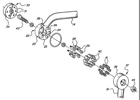
As is best shown in Figure 2, the frame
extension 14 terminates at its forward end in a hub
22 having an annular collar 23 in which is a central
opening 24 encircled by a planar face 25. The
collar has a plurality of arcuately spaced sockets
26 extending inwardly from the face 25. In
communication with each socket is a passage 27 that
is open at its opposite ends. Slideably
accommodated in each passage is an actuator 28
having a head 29 at one end accommodated in the
associated socket and from which extends a stem 30
having an interiorly threaded blind bore 31.
Accommodated in each bore is a threaded bolt 32.
An operating member 33 confronts that end
of the collar 23 opposite the sockets 26 and
comprises a disk 34 having a plurality of openings
through which the shank of the bolt 32 extends. The
disk 34 also has a plurality of circumferentially
spaced openings 35 in which the heads 36 of the
bolts 32 are accommodated.
- 6 -
CA 02228918 1998-02-06
WO 97/07447 PCTJUS96/13148
At the upper end of each of the foot rest
supports 16 and 17 is a hub 37 having an annular
collar 38 that is provided with a plurality of
circumferentially spaced bores 39 therein.
Accommodated in each bore 39 is a locking pin 40
which is yieldably biased by a spring 41 to move in
a direction outward of the associated bore.
The hub 37 has an annular boss 42 which
extends into the central opening 24 of the hub 22
and provides a journal on which the hub 22 is
rotatable. The hubs 22 and 37 have aligned openings
through which a retaining bolt 43 extends, the bolt
having a head 44 at one end and a nut 45 at the
opposite end. The retaining bolt 43 forms an axis
about which the hubs 22 and 37 are rotatable.
In the embodiment shown in Figures 3 - 5B,
there are eight sockets 26 circumferentially spaced
about the axis A. Each socket is uniformly spaced
from its adjacent socket and each socket is spaced
radially an equal distance from the axis A.
In the embodiment shown in Figures 3 - 5B,
the hub 37 has six circumferentially spaced locking
pins 40. The arcuate spacing between adjacent
locking pins 40 is uniform and the radial spacing of
each locking pin from the axis A also is uniform and
corresponds to the radial spacing of the sockets 26.
Although the circumferential spacing between
adjacent locking pins 40 is uniform, such spacing
differs from that of the sockets 26 since there are
- 7 -
CA 02228918 1998-02-06
WO 97/07447 PCT/US96/13148
fewer locking pins than there are sockets. The
arcuate spacing between each adjacent socket is 450,
wherein the arcuate spacing between adjacent locking
pins 40 is 60 The difference in the angular
spacing between the sockets and pins, therefore, is
15 .
In the condition of the parts shown in
Figures 3 and 5a, two of the locking pins 40 are
accommodated in two diametrally opposite sockets 26.
The remaining locking pins bear upon the smooth face
25 of the collar 23. The two hubs 22 and 37,
together with their respective members 14, 16, are
disabled from relative rotation, because of the
accommodation of the two locking pins in two of the
sockets. As is best shown in Figure 3, the locking
pins 40 fit fairly snugly within the sockets 26 so
as to minimize relative rotary movement between the
hubs when they are disabled from relative rotation.
When it is desired to enable relative
rotation between the hubs 22 and 37, the operator 33
is displaced to the right from the position shown in
Figure 3 to the position shown in Figure 4 by the
application of a force F1. Such movement of the
operator 33 will effect corresponding movement of
all of the actuators 28 a distance to enable those
.
locking pins 40 that are projected into the socket
to be displaced and occupy a position in which each
locking pin 40 is wholly withdrawn from the sockets
26. See Fig. 4. It is essential that the movement
- 8 -
CA 02228918 1998-02-06
WO 97/07447 PCT/US96/13148
of the actuators 28 be sufficient to effect complete
withdrawal of all of the locking pins 40 from the
sockets 26, but the movement should not be so great
as to cause any part of an actuator 28 to project
into any of the bores 39. The appropriate extent of
movement of the actuators may be controlled by the
extent to which the bolts 32 are threaded into the
bores 31.
Once all of the locking pins 40 have been
withdrawn from the sockets 26 relative rotary
movement between the hubs 22 and 37 is enabled. As
long as the force F1 is applied to the operator 33 to
maintain the parts in the positions shown in Figure
4, relative rotation between the hubs 22 and 37 is
unlimited. However, if the force applied to the
operator 33 is removed following sufficient relative
rotation of the hubs so that no locking pin projects
into a socket 26, further relative rotation between
the hubs will be limited to that which enables a
locking pin 40 to register with one of the sockets
26. Whereupon the spring 41 of the in-register
locking pin will project the pin into the socket 26,
thereby effecting displacement of all of the
actuators 28 associated with the projected locking
pins and restoration of the operator 33 to the
position shown in Figure 3. If desired, a spring
(not shown) could be interposed between the cap 34
and the hub 22 so as to encircle the head 44 of the
bolt 43 and exert a yieldable force on the operator
- 9 -
CA 02228918 1998-02-06
WO 97/07447 PCT/US96/13148
tending to return it and all of the actuators 28 to
their retracted positions.
If the force F1 is removed following
relative rotation of the hubs 22 and 37 to a
position in which the projected locking pins 40 are
withdrawn from the associated sockets 26 and bear
upon the smooth face 25 of the hub 22 between
adjacent sockets, further rotation in the same
direction will cause one or more locking pins to be
projected into those sockets with which they are in
register. From a comparison of Figures 5A and 5B,
relative rotation between the hubs 22 and 37 through
increments of only 15 will cause two locking pins
to be projected into two sockets 26 but these
locking pins and sockets will be different from the
locking pins accommodated in the sockets as shown in
Figure 5A. In the disclosed embodiment, relative
rotation of the hubs 22 and 37 through 15 will
enable two diametrally opposite locking pins to be
projected into two diametrally opposite sockets,
thereby disabling further relative rotation between
the hubs.
In the embodiment shown in Figures 6A and
6B, there are eight locking pins 40 and nine sockets
26. The angular spacing between adjacent sockets is
40 , whereas the angular spacing between the
adjacent locking pins is 45 . The difference in the
angular spacings, therefore, is 5 . Consequently,
relative rotation of the hubs through increments of
- 10 -
CA 02228918 1998-02-06
WO 97/07447 PCT/US96/13148
only 50 (when all locking pins are withdrawn from
the sockets) will enable one or more locking pins to
be projected into one or more sockets, as is shown
in Figure 6B, thereby disabling further relative
rotation between the hubs. As will be apparent from
Figures 6A and 6B, only one locking pin in this
configuration of pins and sockets is projected into
a socket at any one time.
Other combinations of sockets and locking
pins are possible. For example, Figures 7A and 7B
show nine sockets 26 spaced 400 apart and six
locking pins spaced 60 apart. The difference in
the spacing, therefore, is 20 so that each
increment of relative rotary adjustment of the hubs
is 20 . In the embodiment shown in Figures 7A and
7B, three locking pins will be accommodated in three
sockets when the hubs are disabled from relative
rotation.
In the embodiment shown in Figures 8A and
8B, there are 19 sockets and 20 locking pins.
Consequently, relative rotation between the hubs may
be disabled in response to increments of slightly
less than 1 of angular adjustment.
In the embodiment shown in Figures 9A and
9B, there are 18 sockets and 17 locking pins. It
thus is possible to provide for incremental angular
adjustment between the hubs of slightly more than
1 .
- 11 -
CA 02228918 1998-02-06
WO 97/07447 PCTIUS96/13148
Other changes in the numbers of sockets
and locking pins may be made. In all instances,
however, there will be a difference in the number of
locking pins and the number of sockets. The
difference will depend upon factors such as the
degree of incremental relative rotation desired and
whether only one or more than one locking pin should
be accommodated in a socket at any one time. The
number of locking pins accommodated in sockets at
any one time, of course, will affect the ability of
the hubs to resist shearing of the locking pin or
pins.
The embodiment shown in Figures 10-12 is
similar in many respects to the embodiment just
described, but differs in some of its structural
characteristics. In the modified embodiment the
frame member 14 is secured to a hub 46 comprising an
annular body 47 having a smooth face 48 at one end
which encircles a central bore 49. At its opposite
end the body 47 has an annular extension 50 which
lies radially inward of an annular face 51 in which
is a plurality of circumferentially spaced sockets
52.
Confronting the hub 46 is a second hub 53
having a bore 54 in which the extension 50 is
rotatably accommodated. The hub 53 has an annular
body 55 and that face of the body 55 which confronts
the hub 46 has a plurality of circumferentially
spaced cavities 56 in each of which is a
- 12 -
CA 02228918 1998-02-06
WO 97/07447 PCT/US96/13148
reciprocable locking pin 57. Each locking pin has a
reduced diameter actuator 58 which extends through
an opening 59 formed in the adjacent face 60 of the
hub 53. A spring 61 yieldably biases the associated
locking pin 56 to the projected position shown in
Figure 11.
The hubs 46 and 53 are maintained
assembled in relatively rotatable condition by a
central shaft 62 having a head 63 at one end and a
nut 64 at its other end. The shaft 62 defines an
axis B about which the hubs are relatively
rotatable.
Each of the actuators 58 slideably extends
through an opening 65 formed in an operator 66
comprising a ap or disk 67. Secured to the free end
of each actuator 58 is bolt 68 having an enlargement
69 which is adapted to bear against the outer
surface 70 of the disk 67. Each of the actuators 58
is moveable relative to the disk 67 and the
enlargements 69 of the associated bolts 68 limit
relative movement of the disk 67 in one direction
relative to the associated actuator. Secured to the
disk 67 is an extension 71 which may be gripped by a
person to effect movement of the actuators and all
of the associated locking pins 57 simultaneously.
As is the case with the first-described
embodiment, the hub 46 has a plurality of
circumferentially spaced sockets 52, each of which
is spaced uniformly from the axis B. The arcuate
- 13 -
CA 02228918 1998-02-06
WO 97/07447 PCT/US96/13148
spacing between adjacent sockets is uniform. The
hub 53 carries a plurality of circumferentially
spaced locking pins 57, the radial spacing of which
from the axis B corresponds to that of the socket
52. The number of locking pins 57 is different from
the number of sockets 52, as is the case in the
first-described embodiment, and the number of
locking pins may be either fewer or greater than the
number of sockets. However, the arcuate spacing
between adjacent locking pins is uniform.
When the parts are in the positions shown
in Figure 11, at least two of the locking pins 57
occupy a projected position in which they are
accommodated in two of the sockets 52. The
projected locking pins bridge the joint between the
hubs 46 and 53 and, accordingly, disable relative
rotation therebetween. Those locking pins which are
not accommodated in sockets bear against the smooth
face of the hub 46 between adjacent sockets. Thus,
the actuators of the locking pins which do not
project into the socket occupy a position different
from that of the projected locking pins.
When it is desired to effect relative
rotation between the hubs 46 and 53, the operator 66
may be moved in a direction to withdraw the
projected locking pins from the sockets by the
application of a force F. on the extension 71. See
Figure 12. This will cause the disk 67 to engage
the enlargements 69 of the bolts 68 and effect
- 14 -
CA 02228918 1998-02-06
WO 97/07447 PC'd'lUS96/13148
simultaneous withdrawal of all of the projected
locking pins to the retracted position shown in
Figure 12 in which no part of a locking pin extends
into any socket. The hubs 46 and 53 then may be
rotated relative to one another.
As long as the force F2 is applied,
relative rotation between the hubs 46 and 53 is
enabled. When the force F2 is released, however, the
spring 61 associated with each locking pin will
enable any locking pin that moves into register with
a socket 52 to be projected into such socket,
thereby disabling further relative rotation of the
hubs.
As is the case in the first embodiment,
the difference in the number of locking pins and
sockets enables incremental relative arcuate
adjustment of the hubs through virtually any
selected arc. In the form shown, there are eight
sockets 52 and six locking pins. The spacing
between adjacent sockets is 450 and the spacing
between adjacent pins is 600. The hubs, therefore,
are capable of incremental rotation of 15 between
successively fixed positions.
In the disclosed embodiments the hubs are
capable of relative rotation through 360 . However,
the principles of the invention are applicable to
constructions wherein such extensive rotation is not
necessary. If, for example, rotation through only
- 15 -
CA 02228918 1998-02-06
WO 97/07447 PCT/US96/13148
180 is required, the number of locking pins and
sockets may be decreased.
The disclosed embodiments are
representative of presently preferred forms of the
invention, but are intended to be illustrative
rather than definitive thereof. The invention is
defined in the claims.
- 16 -