Note: Descriptions are shown in the official language in which they were submitted.
CA 022290~7 l998-02-09
WO 97/07490 PCT/GB96/01919
M~R~FR A.~SFMR~ Y
This invention relates to marker assemblies CO~ ,illg a support sheet having a
surface provided with a porous coating of latent curable material capable of receiving
printed indicia, which coating is capable of being subsequently cured to render the
indicia s~bst~nti~lly indelible.
Such marker assemblies are described in our EP-B-0237258, and one commercially
successful form thereof comprises a 50-miclollleLlc-thick polyester support sheet having
a layer of adhesive on the surface not carrying the porous coating and having a silicone-
coated release paper removably adhering to the adhesive. These known assemblies are
very successful for use with roll-fed ~lhlLel~, but have unexpectedly proved at times to
be llncuit~ble for sheet-fed ~lhlL~l~ requiring a supply of sheets in the A3 to A5 size-
range, preferably A4. The present invention provides sheets in that size-range using a
new col~Llu-;Lion of marker assembly for improved sheet-fed printing.
The invention accoldingly provides a marker assembly in substantially rectangular
form of edge dimensions not greater than A3 sheet size and not less than A5 sheet size,
comprising
(i) a support sheet having a surface provided with a porous coating of latent
curable material capable of receiving printed indicia, which coating is
capable of being subsequently cured to render the indicia substantially
indelible, the porous coating preferably being in particulate and/or
fila ll~llL~l y form,
(ii) a layer of adhesive on the surface of the support sheet not carrying the
porous coating, and
(iii) a plastics release sheet of at least 90 micrometres thil~l~ntoss removably adhered to and covering at least part of the adhesive layer.
The specified construction may be adapted to promote a number of commercially
attractive features in the arol~,.llellLioned sheet sizes. The plastics release sheet of 90
miclolll~Ll~,s or more thi-~n~cs tends to resist curling, which has been found to be a
CA 022290~7 l99X-02-09
WO 97/07490 PCT/GB96/01919
--2--
problem with the known silicone release papers in A4 size sheets. It is well adapted to
die cutting of individual ll~ lS from the printable sheet, being less prone to accidental
tnrough-cutting of the release sheet, which has been found to occur when the curling
problem was addressed by using certain release papers coated on both sides with silicone
release agent. It tends to resist multi-sheet feedings, which can be caused by
ele~;L~o~L~Lic attraction when thinner plastics release sheets are used, for example 50-
mic,lo",~Ll~-thick polyester sheet similar to that used for the known support sheet. And
most ullw~e~;Ledly, at 90 micrometres or more thicknl-c.c it can be, and preferably is,
made from econnm~ y-advantageous plastics sheet which has not been stress-relieved,
unlike the preferred support sheet which is stress-relieved to render it heat-stable under
at least some conditions subsequently used to cure heat-curable porous coatings. Thinner
release sheets made from non-stress-relieved plastics (e.g. polyester) sheet of 50 or 75
lllic.~,llletres thickn~sc have been found to become unacceptably distorted during such
curmg.
The upper thir~npss limit of the release sheet is not critical, provided that the
reslllting assembly remains suitable for the sheet-fed L~lhlL~,~ in question, but it will
generally be economically preferable to use thi~kll~osces near the specified minimllm, for
example within the range from 90 to 120 or 90 to 110 mi~,,olllctl~s, thi~'vnt-cces of 95 to
105, preferably close to 100, mi.;,ome~les being convenient for polyester release sheets,
which are ~,lerc.l~,d, especially in conjunction with polyester support sheets. The release
sheet may be made of an inherently non-adherent plastics material, but will preferably
have a surface coating of a known release material, for example polysiloxane (silicone)
release coatings, since this allows greater freedom of choice for the release sheet
material to suit sheet feeding and econolllic requil~m~,lL~.
The components of the assembly other than the release sheet may be as described
in EP-B-0237258, the disclosure of which is incorporated herein by reference. The
release sheet may be made of plastics selected from to those described for the support
sheet in EP-B-0237258, but polyesters are ~le~ll~d, especially when the support sheet is
made of polyester.
CA 022290~7 1998-02-09
W O 97/07490 PCT/GB96/O1919 --3 --
As a specific example to illustrate the invention, an A4-sized marker assembly
accoldillg to the invention may be made using known assembly m~othn-i~ from a support
sheet of So-miclolllell~s-thick heat-stabilised (stress-relieved) white Melanex ST529
(Trademark) polyester sheet from ICI, coated on one side with a curable porous layer as
described in EP-B-0237258, and coated on the other side with a solvent-based ples~ule-
sensitive acrylic adhesive available from National Starch and ChPmir~l Ltd. under the
Tr~1Pm~rk Durotak 180-1197, the solvent being removed after coating. The dry
adhesive coating is overlaid with a 100-micrometres-thick clear Melanex (Tra(l,om~rk)
Type S polyester sheet from ICI having a silicone release coating pre-applied to the
surface facing the adhesive. Sheets of A4 size cut from this assembly by known methods
have been found satisfactory for sheet-fed printing in known inkjet p~ el~.
The invention includes a method of producing markers coln~~ g printing indicia
on the porous coating of one or more of the novel assemblies hereinbefore described by
means of a sheet-fed printer, preferably an inkjet printer, and preferably including the
step of curing, preferably heat-curing, the printed porous coating to render the indicia
subst~nti~lly indelible .
The substantial indelibility of the indicia may be deterrnined as described in EP-B-
0237258, the disclosure of which is incorporated herein by reference.
The present invention includes a feature for advantageously reducing sheet-to-sheet
adhesion, which adhesion may hinder feeding of the sheets individually from a stack
thereof owing to electrostatic attraction and/or vacuum suction and/or frictional forces
between sl-rcessive sheets in the stack.
The invention accordingly provides a marker assembly as hereinbefore described,
wh~leill the exposed surface of the said plastics release sheet facing away from the
rem~in~er of the assembly has spacing means projecting thel~rlolll capable of
m~int~ining one or more air gaps between the said release sheet and the adjacent porous
coating of an ~ cPnr similar assembly when in a stack of such assemblies, the said
spacing means being arranged to provide the said air gap(s) at least in an edge region of
CA 022290~7 l99X-02-09
W O 97/07490 PCT/GB96/01919 --4--
the assembly which will be the leading edge region when fed from a stack of suchassemblies to sheet h~nflling e~lui~ e.l~ in use, thereby facilit~ting separation of
individual assemblies from the stack.
The advantages of marker assemblies having a reduced tendency to stick together
in a stack will be self-explanatory, regardless of whether the individual assemblies
(hereinafter sheets) from the stack are fed to the sheet h~n~lling equipment by means
external to that e~ui~ lt, or are pulled into the equipment by means incorporated
therein.
A single air gap may be envisaged extenrling around the edges of a centrally-placed
spacing means or ext.on~ling in and out between a relatively large number of small
projecting spacing means in the forrn of pads or "islands". In theory, such discrete
projecting spacing means could become more numerous and smaller progressively until
so~ l,h-g approaching a coating of minute glass beads on the sheet surface might be
achieved. However, such small projections may be less satisfactory than larger
projecting surfaces from the point of view of friction against the adjacent porous coating
of an adjacent sheet when one sheet slides over the other during the feeding operation.
The sheet h~n-lling equipment will usually be a sheet-fed printer, for example an ink jet
printer, or heating equipment used for curing the indica-bearing coating after printing, or
other devices such as die cutters, conveyor belts etc.
It is pl~relled that the spacing means comprises at least one strip of plastics
material adhered to the said release sheet. Whether adhered to the release sheet or
formed integrally with it, the spacing means preferably comprises a single strip of
material substantially centrally aligned with the inte~-led direction of feed of the
assembly in use. It will be understood that a single straight strip of material running
more or less down the centre of the sheet in the direction of feed will often be the most
economical form of spacing means. However, the shape of the spacing means is notnlocess~rily limited to straight-edged rectangular strips.
CA 022290~7 1998-02-09
W O 97/07490 PCT/GB96/01919
_ 5 _
When a single spacing strip is used as aforesaid, it is L)l~r~LIed that the width of the
single spacing strip is at least 25 mm, preferably at least 50 mm, more preferably at least
one third and not more than two thirds of the total width of the assembly, and preferably
not more than 125 mm. Dimensions within these ranges may be selected so as to spread
the effect of the two air gaps running down the opposed edges of the spacing strip to the
most effective positions across the width of the sheets in the stack.
Single spacing strips are not however esse~ti~l, and the spacing means may
comprise two or more strips of material, preferably subst~nti~lly symmetrically aligned
with the intended direction of feed of the assembly in use.
In some cases, it may be sufficient to provide the spacing means and air gaps only
in the region of the leading edge of the sheets, or extending only part way from the
leading edge towards the opposite trailing edge of the assembly. However, it will
usually be preferable that the spacing means and the air gap(s) extend continuously from
the leading edge of the assembly to the opposite trailing edge of the assembly. In such a
structure, the sheet-to-sheet adhesion-reducing effect of the air gaps will be felt over the
entire length of the sheet instead of just a leading portion.
It is ~.refell~d that the spacing means has a subst~nti~lly sheet-like smooth exterior
surface facing away from the rem~in-ler of the assembly, since this will tend to reduce
sliding friction between adjacent sheets as they are fed one by one from the stack. It is
nnn~cecs~ry to quantify exactly the degree of smoothness of the spacing means exposed
surface, but it is clearly a case of "the smoother the better" and coherent polymer films
will usually be more satisfactory than rough or corrugated surfaces such as the back of
crepe paper m~cking tape.
It is very much ~lcfelled that the spacing means is adhered to the said release sheet
by an adhesive that permits movement of the spacing means along the surface of the
release sheet at ~ e,~ltures e~ .iellced by the spacing means during curing of the
indicia-receiving porous coating in use. For this purpose, the spacing means preferably
c.,lll~lises a low-tack ~ s~ule-sensitive adhesive protective tape, for example that
CA 022290~7 1998-02-09
W O 97/07490 PCT/GB96/O1919 --6--
available under the trademark "Flowstrip FL205" from Flowstrip T imitr(l of
Sc~lnthorpe, F.ngl~nr1 This is especially relevant when the spacing means co~ ises a
polymeric film material which may undergo some longit~l-lin~l shrinkage at elevated
temp~ld~ules. The movement permitted by the ~lef~lled adhesive allows such shrinkage
to occur without curling to an unacceptable extent the release sheet to which the tape
adheres. It has been found that shrinkage of 2 - 3 mm at each end of the preferred
ple.,~ure-sensitive adhesive tape can thus be accommodated without curling the assembly
as a whole.
The thirl~nrcs of the spacing means is not critical, but it may be preferable that the
spacing means projects from the release sheet to a ~1ict~nre within the range from 25 to
100 micrometres. Pressure-sensitive adhesive tapes of such thickness are accordingly
ple~lled, the afolclllelllioned tape FL205 being approximately 50 micrometres thick.
The marker assemblies according to this invention are especially useful in methods
of feeding the assemblies one at a time from a stack thereof to sheet h~n-lTing equipment,
wl~elcin means are provided for reducing static charge on the assemblies during such
feeding. Such static re~ rti-)n means, for example known anti-static bars, enh~nre the
adhesion-reducing effect of the aforementioned air gaps and have been found to enable
trouble-free feeding of a stack of up to 25 A4-size sheets into a desk top inkjet printer.
It is understood that references in the original co-pending application and herein to sheet
sizes in the A3 to AS size range do not restrict the sheets to "A" proportions. U.S.
quarto, foolscap and other sizes, and the standard sizes of other countries may all be
inrlncled within the overall dimensional range from A3 to AS.
Specific embo-limlontc of the present invention will now be described by way of
example, with le~llce to the accompanying drawings wherein
Figure 1 shows srhlqm~tir~lly in end view a single marker assembly according to
the invention;
Figure 2 shows srhPm~tir~lly a stack of three such marker assemblies in a
(secti~n~ocl) feed tray;
-
CA 022290~7 1998-02-09
W O 97/07490 PCT/GB96/01919
-- 7 --
Figure 3 shows in m~gnifi~otl greater detail an end view of two possible structures
for a marker assembly according to the invention; and
Figures 4 to 6 show sçh~om~tir~lly in plan view different arrang~ . of the
spacing means on the surface of the aforementioned release sheet.
Rt:fe,lillg to the drawings, Figure 1 shows the coated A4 support sheet 10 adhered
by a layer of adhesive (not shown) to a plastics release sheet 12 of at least 90micrometres thir'~n~ss as described in the aforementioned co-pending application, with a
75mm wide strip of the afor~"~ inned FL205 low tack protective tape 14 adhered to the
release sheet 12 in a s!lba~ lly central position with respect to the width of the
assembly as shown in this end view.
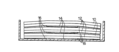
When sheets such as that shown in Figure 1 are stacked in use for feeding through
a printer, as shown in Figure 2, the 50 micrometres thir'~n~ss of the projecting tape 14
will result in air gaps 16 bt;Lv~ee.l the release sheet 12 carrying the tape and the porous
coating of the carrier sheet 10 of the ~ ce~t assembly in the stack. Tne proportions
and shape of the air gaps 16 have been exaggerated for clarity in this diagram.
The structure of the assemblies according to this aspect of the invention is shown
in more detail in tne sC~rltom~tir end view of figure 3. The marker assembly culll~lises
the porous coating (30) of latent curable material capable of receiving printed indica,
which coating is carried on the support sheet (32), the opposite surface of which carries
the layer of adhesive (34) to which is adhered tne plastics release sheet (36), all as
described in the arol~;l"~,llioned co-pending application. This A4 assembly is
approximately 210 mm in width and the various layers con~titl-tin~ it may for example
be 60 miclullleLl~,s thick curable coating (30), 50 micrometres tnick Melinex (tr~lem~rk)
ST 529 support sheet (32), 10 mi(;lullleLles thick ~ .aule-senSitive adhesive (34), and
100 micrometres tnick Melinex (trademark) type S release sheet (36). The 50
miclulllt:Ll~,s thick FL 205 low tack protecLive tape (38) is adhered to the exposed surface
of the release sheet (36) by its low tack adhesive layer (40) and produces air gaps (42),
c~llesL)olldi~g to air gaps (16) of Figure 2 as srhtom~tir~lly inrlir~t~ by broken lines in
Figure 3.
CA 022290~7 1998-02-09
W O 97/07490 PCT/GB96/01919 --8--
In an alternative embodiment of the invention, the tape (38) of 75 mm width could
be replaced by three strips (44) of similar tape of 25 mm width evenly spaced across the
width of the assembly and e~rrnrling from the leading edge all the way to the trailing
edge as afol~l"~ )ned. In such an arrangement, there would be four air gaps (46) as
srhPnn~tit~lly in-1ic~tt-d by the broken lines associated with the three strips of tape (44).
Figure 4 illustrates sch~m~tir~lly the preferred alldllgelllt;llL of a single strip of
spacing tape (14) positioned subst~nti~lly centrally and extending all the way from the
leading edge to the trailing edge of the release sheet (12) of a structure similar to Figure
1 as viewed from below.
Figure 5 shows possible alternative structures having three strips of tape (44)
extrn~ing only part way from the leading edge towards the trailing edge, with possible
further short strips (45) indicated in broken lines to extend the spacing effect over more
of the sheet area.
Figure 6 shows another possible, though generally less preferred, alternative
having a number of smaller round portions of spacing tape (50) distributed over the
surface of the release sheet (51).