Note: Descriptions are shown in the official language in which they were submitted.
CA 02229321 1998-02-10
1
IMAGE DISPLAY APPARATUS
This invention relates to image display
apparatus, for example to large field of view image
display apparatus that may be used in flight, vehicle,
marine and leisure simulators.
Large field of view image display apparatus often
comprises a number of display projectors, each
projecting an image on t.o a single screen. These
images are arranged in such a way that they appear as
one overall image to the user. Where one image joins
its neighbour, a technique called blending is
typically used. Each image is positioned so that it
overlaps the neighbouring image and, within the
overlap region, one image is progressively faded out
whilst the other image is progressively faded in, such
that at any one point within the overlap region, the
contribution from each image, when added together,
equals that of a single image. Hence, the intensity
of the overall image at any point in the overlap
region should be equal to that of the image on either
side of the overlap region for a given image
intensity.
In some types of image display apparatus, more
than two images may be overlapped at any one point in
the overall image. Typically, four single images may
CA 02229321 1998-02-10
2
overlap at their corners in very large field of view
display apparatus. The same technique of fading the
single images is used to form one continuous image of
the correct intensity throughout the overlap region.
This blending technique is normally performed by
modulating a video signal to the display apparatus.
Hence, a modulation waveform is generated and this is
multiplied with the video signal. This operation may
either be formed within the display projector itself,
or within a separate apparatus. Where the operation
is within the separate apparatus, then the apparatus
may be capable of performing the modulation of the
video signals to a single display projector, or to a
number of display projectors.
The waveform generated to modulate the video
signal must take into account the response of the
image display apparatus, to the video signal,. in
order that the combined. image from all display
projectors form an over;~ll image of the correct
intensity in the overlap region. The response of the
image display apparatus is typically non-linear and
has what is known as a gamma function. The non-
linearity in the display projector response adversely
affects the final image display.
It is an aim of the present invention to obviate
or reduce the above mentioned problem.
CA 02229321 1998-02-10
3
Accordingly, in one non-limiting embodiment of
the present invention there is provided image display
apparatus comprising at least one display projector
for displaying an image, signal generator means for
generating a control signal for controlling the
intensity of the image, modulator means for generating
a modulation waveform for modulating the intensity of
the image, and adjustor means for adjusting the
modulation waveform for improving the performance of
the modulation waveform at various image intensities,
the image display apparatus being such that it uses
different modulation waveforms for various image
intensities, it uses a proportion of at least one
modulation wave form in dependence upon the control
signal, and it uses the resultant modulation wave
form to modulate the control signal.
The image display apparatus of the intention
compensates for non-linearity in the display projector
response. The image display apparatus is able to work
well with display projectors having various non-linear
characteristics. If the image display apparatus is a
non-linear response (video signal versus intensity of
image on the display) tY~en the modulation waveform
should be adjusted, in dependence upon the amplitude
of the video signal into the display projector. This
CA 02229321 1998-02-10
4
is especially so where a good quality blend is
required between two or more single images.
The image display apparatus may include selector
means for selecting a proportion of more than one
image modulation signal, the selector means being
controlled by the control signal for the image display
apparatus . The control signal may be a drive signal .
The drive signal may be a video drive signal.
The image display apparatus may be a monochrome
or colour image display apparatus.
The image display apparatus may comprise a single
display projector, or a plurality of the display
projectors.
The image display apparatus may be one in which
the modulation waveform is used for blending multiple
single display images together. Alternatively, the
image display apparatus may be one in which the
modulation waveform is used to modify modulation
waveforms used for other purposes, for example a
colour shading waveform for boosting the intensity of
the image in an area of the display, perhaps to
compensate for the reduced intensity of an image
towards its extremes.
The image display apparatus may be one in which
the signal generator means and the modulator means are
provided in the display projector.
CA 02229321 2006-05-15
The image display apparatus may be one in which the
display apparatus is such that it is able to adjust the
modulation waveform for a single or multiple display
projector.
5 The image display apparatus may be one in which the
image display apparatus selects a proportion of each
modulation waveform in dependence upon the control
signal. Alternatively, the image display apparatus may
be one in which the image display apparatus combines 100
of one modulation waveform with a proportion of another
modulation waveform.
In accordance with an aspect of the invention there
is provided an image display apparatus comprising at
least one display projector for displaying an image,
video signal generator means for generating a video
control signal for the display projector, modulator means
for modulating the video control signal for the display
projector, modulation waveform generator means, and
adjustor means for adjusting the modulation waveform for
improving the performance of the modulation waveform at
various image intensities, the image display apparatus
being such that it uses different modulation waveforms
for various image intensities, and the adjustor means
being such that it selects a proportion of each
modulation waveform in dependence upon the amplitude of
the control signal from the video signal generator means,
and it uses the resultant modulation waveform to modulate
the control signal.
An embodiment of the invention will now be described
solely by way of example and with reference to the
accompanying drawings in which:
DOCSOTT: 472408\1
CA 02229321 2006-05-15
5a
Figure 1 shows the response of a sample display
projector from black to peak white;
Figure 2 shows the possible shape of a modulation
waveform to blend two images together for the sample
display projector referred to in Figure 1;
Figure 3 shows the response of a display projector
at different drive levels;
Figure 4 shows blend modulation waveforms for
different drive levels;
Figure 5 shows a blend intensity profile using one
blend modulation waveform at different drive levels;
DOCSOTT: 472408\1
CA 02229321 1998-02-10
6
Figure 6 shows a blend intensity profile using
the modulation waveform from the image display
apparatus of the present :invention at different drive
levels; and
Figure 7 shows the image display apparatus of the
present invention.
Referring to Figure 7_, the waveform generated to
modulate the video signal must take into account the
response of the image display apparatus to the video
signal, in order that the combined image from all
display projectors forms an overall image of the
correct intensity in the overlap region. The response
of known image display apparatus is typically non-
linear and has what is known as the above mentioned
gamma function. The response of a known display
projector having this typ9-cal non-linear response and
the gamma function is shown in Figure 1.
Figure 2 shows the possible shape of a modulation
waveform to blend two images together for the display
projector shown in Figure 1. The modulation waveform
shown in Figure 2 is based on the inverse of Figure 1.
Thus the modulation waveform shown in Figure 2 assumes
that the image display apparatus is modulating the
image from peak white to black, ie the complete image
is peak white in the blend region. This will not
always be the case.
CA 02229321 1998-02-10
7
Figure 3 shows the response of a display
projector at different drive levels. More
specifically, Figure 3 shows the response of the
display projector used in Figure 1 from black up to
100%, 50% and 12.5% of its peak white drive level.
Figure 4 shows blend modulation waveforms for
different drive levels. More specifically, Figure 4
shows the required shape of a modulation waveform in
each of the cases envisaged for Figure 3. The exact
shape is not critical. When a number of single images
are overlapped, then at any one point in the overlap
region, the sum of all the single images should
produce the same intensity as if it had been one large
continuous image.
If the image overlap region is modulated by a
modulation waveform based on the image display
apparatus operating at 100% peak white drive level,
then it may be questioned what happens when the image
display apparatus actually operates at lower drive
levels, for example when the image being projected is
grey. Figure 5 shows the intensity through the
overlap region when the 100% drive modulation waveform
is used, but the image display apparatus is actually
operated not only at 100%,. but also at 50% and 12.5%
drive levels . In the cases of the 50% and the 12 . 5%
CA 02229321 1998-02-10
8
drive levels, there is a droop in intensity of the
image through the overlap region.
In order to part_Lally overcome the above
mentioned problem referred to with reference to Figure
5, the image display apparatus could be set upon with
a compromise modulation waveform, for example the 50%
Max Drive curve of Figure 4. The compromised
modulation waveform could be one that caused peaking
of intensity of the blends of bright images, and
drooping in intensity in t:he blends of darker images .
Users may also be able to~ compensate for this effect
using one modulation waveform for bright images and
changing to another for dark images. However, this
does not work well in many images where there are both
bright and dark areas of image, for example with an
image containing bright areas of sky and dark areas of
land or sea. Another complication is that the image
(and hence areas of dark and bright image) are moving
in many applications, so that a technique of using
different modulation wavei'orms for fixed areas would
not work very well.
It is known to use a digital system in which a
number of look up tables are used and selected
according to scene brightness. This digital system
works reasonably well and it uses a number of look up
tables for different image intensities. Each look up
CA 02229321 1998-02-10
9
table contains the characteristic of the image display
apparatus for different image intensities. The look
up table is used to modify the modulation waveform to
match the image display <~pparatus. The video drive
signal to the image display apparatus is sampled by an
analog to digital converter and the output from the
analog to digital converter is used to select the
appropriate look up table. The samples are taken many
times per horizontal video line and these samples are
used to select the appropriate look up table for the
next video line. Applying the samples to the next
line avoids any lag or offsets, introduced by the
sampling time. Alternatively, samples could have been
applied on the next video frame had a larger sample
memory been used.
The known digital system using the look up tables
has problems. More specifically, a large quantity of
electronics is required to achieve the required
solution. Also, the quantity of data required to be
stored in the look up tables is very large and, for
example, there may be eight look up tables for each
colour . The performance of the known digital systems
is limited by the number of samples taken along each
line. Ideally, a sample would be taken and the
appropriate look up table selected for each pixel in
CA 02229321 1998-02-10
10
the display's image, but t=his would however require a
lot of complex electronics.
The image display apparatus of the present
invention overcomes the problems mentioned above and
is also able to vary the length of the modulation wave
form dependent upon the signal drive signal to the
image display apparatus. This is achieved with very
little electronic circuitry. One method of operation
of the image display apparatus of the present
invention assumes a linear interpolation (dependent
upon signal drive level) between the modulation wave
form required for 100% signal drive level and 0% drive
level would achieve approximately the correct signal
drive level. In such a method, there are two
correction waveforms, one for 0% video drive and one
for 100% video drive. A fader then selects a
proportion of each correction waveform, dependent on
video drive levels. An alternative method of
operation of the image display apparatus of the
present invention is where there is one correction
waveform, for example for 0% video drive, and there is
a second waveform which when added to (or subtracted
from) the correction wavef:orm, will give the required
waveform at 100% video drive. A fader then add (or
subtracts) a proportion of: the second waveform to the
CA 02229321 1998-02-10
11
correction waveform, dependent on the video drive
level.
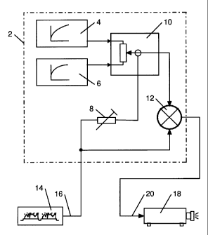
Referring now to Figure 7, there is shown image
display apparatus 2 of the present invention. The
image display apparatus 2 comprises a modulation wave
form generator 4 for :L00~ video drive, and a
modulation wave form generator 6 for 0~ video drive.
The image display apparatus 2 also comprises a
variable gain device 8, a video signal fader 10, and a
video multiplier 12. Figure 7 only shows one path and
the stated parts 4, 6, 8, 10, 12 would typically be
duplicated for each colour,, that is for red, green and
blue.
The modulation waveform generators 4, 6 provide
the correct waveforms for the brightest and for the
dark image. The modulation wave form generators 4, 6
may be digital circuits with digital to analog
converters. Alternatively, the modulation waveform
generators 4, 6 may be entirely analog circuits.
Typically, the modulation waveform generators 4, 6
would share the majority of. their circuitry, and would
only have different output stages.
A video drive signal from a signal generator 14
is fed along video input line 16 to the variable gain
device 8. The video drive signal is adjusted to
ensure that black (zero intensity on a display screen)
CA 02229321 1998-02-10
12
will set the video signal fader 10 to one extreme, and
that white (full/peak intensity on the display screen)
will set the video signal fader 10 to the other
extreme. The variable gain device may be fixed
resistors, variable resistors or some electronic gain
control means.
The normalised video :input from the variable gain
device 8 is used to control the video signal fader 10.
Thus, dependent upon the video signal drive level, a
proportion of each modulation wave form will be
selected to ensure a correct modulation waveform for
the video drive level at that point on the display
screen.
The output from the video signal fader 10
modulates the video signal to a display projector 18,
using the video multiplier 12. The video output from
the video multiplier 12 passes along line 20 to the
display projector 18. The' video signal fader 10 and
the video multiplier 12 may typically be integrated
circuits.
The response of the circuit for video drive
levels at 100%, 50% and 12.5% is shown in Figure 6.
If Figure 6 is compared with Figure 5, it will be seen
that there is a marked improvement. Figure 6 results
from using a modulation wave form based on 12.5% drive
CA 02229321 1998-02-10
13
level rather than 0% for t:he dark modulation waveform
generator.
The image display apparatus of the present
invention has the following advantages.
1. Instantaneous response.
2. Works with both static and moving images.
3. Works with dark, bright and mixed intensity
images with no user adjustment once calibrated.
4. Works with small or large areas of intensity
changes.
5. Requires very little circuitry or other means to
implement.
6. Is reasonably straightforward to calibrate.
The required calibration may be such that the
variable gain device 8 is set up using an oscilloscope
or similar. Alternatively, if test modulation
waveforms replace the operational modulation
waveforms, then a set up by eye may be made with
reference to image on the display.
There may be just two modulation waveforms or
alternatively there may be more than two modulation
waveforms. For example, there may be one modulation
waveform for each of red, green and blue. The
modulation waveforms may be pre-set approximating to
the known characteristics of the image display
apparatus. Alternatively, the modulation waveforms
CA 02229321 1998-02-10
14
may be variable to allow a user to optimise them for
the actual characteristics of the image display
apparatus. In this latter case, grey scale images or
a number of uniform images at various video drive
levels may be used to optimise the modulation
waveforms.
It is to be appreciated that the embodiment of
the invention described above with reference to the
accompanying drawings has been given by way of example
and that modifications may be effected. Thus, the
description with reference to the drawings applies the
technique of modulation waveforms for blending a
number of small images to produce one large seamless
image. If desired however the modulation waveform
technique could equally well be applied to any display
modulation waveform, for example one for boosting the
intensity of the image in one area of a display and
for reducing it in another area of display.