Note: Descriptions are shown in the official language in which they were submitted.
CA 02229337 1998-03-09
W O 97/09931 . PCTrUS96/14576
NASOPHARYNGEAL WASH COLLECTION DEVICE
The present invention relates to a device for
delivering and collecting fluids and, more particularly,
to a self-contained manual device adapted for rapid and
repetitive delive~y and collection of a ~luid.
Oftentimes, 2s part of a medical procedure, a
physician is required to collect 2 specimen f~or culture
(typically 2 fluic secretion) from a body cavity of a
patient The meaical procedure may, for example, require
that a specimen be taken from the patient's nasopharynx.
T~pically, these specimens are obtained by direct
swa~bing of the affected area However, a more accurate
and preferred method for collecting a specimen involves
the delivery of a ouantity of irrigating solution to the
nasopharyn~ (thereby dissolving the secretion in the
solution) and the subsequent collection of such solution
for analysis in 2 laboratory
The goal OL the above-described collection technique
is to obtain a specimen having z high concentration of
~luid secretion. This task is preferably accomplished by
repeatedly lavaging the nasopharynx with the irrigzting
solution. Accoraingly, it is important that the lavaging
step be conductea with only a minimal loss of irrigating
solution Furthe_, the process is preferably accomplishec
by employing only a relatively small volume of irrigatins
solution. In this fashion, the collected secretion does
not become overlv diluted in the irrigating solution and
hinder the analysis stage Finally, the process is
preferably accomplished withou. c2using undue discomfort
or traum2 to .he p2tient.
CA 02229337 1998-03-09
n
~ o
7 ~ ~ 7 ~ ~ O
--2--
The devices and techniques currently available are unable to
simnlt~neously accomplish these goals. For example, at least one of the
devices ~;ull~llLly available for sampling the nasopharynx requires substantial
wall suction that may prove uncomfortable and tr~llm~tic to the patient. Other
devices such as bulb syringes are unable to effectively deliver fluid against
gravity and, further, are not well-adapted for aspiration of the dispensed fluid.
See, e.g., U.S. Patent 3,785,366 to Davis. Moreover, typical sampling
techniques require substantial cooperation from and movement by the patient,
thereby rendering such techniques useless in children and the elderly. See,
e.g., the method of EP Publication 0-319-501.
One technique ~;ull~,nLly employed by physicians involves the
construction of a collection device from a syringe, which is then filled with
saline and fitted with a section of flexible catheter. The patient is placed in a
generally horizontal position and, thereafter, the flexible catheter is advancedinto the nasal cavity. The solution is then dispersed into the nasal cavity fromthe syringe, and thereafter, it is ~liffi~--lt to recollect the solution in the syringe
because the solution tends to run back along the nasal passage. Further, the
flexible catheter employed to deliver the solution does not facilitate the
recovery process and, in fact, hinders the process due to the rather small
diameter of its opening. Finally, the above-described procedure can be quite
discomforting to the patient and is difficult to perform on children and the
elderly.
It is also necessary, at times, to obtain specimens from such body
cavities as the ear, vagina or rectum. For example, vaginal or rectal sampling
is often required to check for local infections. These samples, which are
currently obtained by swabbing the affected area or by sampling excrement,
would prove more accurate and be accomplished in a less invasive manner by
use of the above-described collection technique. Prior devices proposed for use
in vaginal sampling merely collect draining fluid, rather than aspirating it under
CA 02229337 1998-03-09
7 ~ ~ O
. positive pressure, and thus tend to have low collecting efficiency. See, e.g.,
U.S. Patent 4,709,705 to Truglio.
There is also a need in the medical field for a device which can deliver
medication to a body cavity. The device is preferably capable of delivering a
relatively large volume of medication to a body cavity. The particular
procedure may also require that the delivered medication be promptly removed
from the body cavity of the patient. For example, when treating a cancer of
- the nasal passage, it may prove medically desirable to deliver a relatively large
volume, high concentration of a toxic agent to the passage. This agent must be
quickly and entirely delivered to the nasal cavity and then quickly and entirelywithdrawn. Again, the devices currently available are unable to accomplish
this task.
There is a further need in the art for a device which would allow
cleansing of a surface through repetitive lavaging of such surface with an
irrigating solution. Accordingly, this same device must be capable of readily
collecting the discharged solution once such solution has pooled.
SUMMARY OF THE INVENTION
The present invention, which addresses the needs of the prior art,
provides a self-contained m~ml~l device for delivering and collecting fluid.
The device includes a container for holding the fluid. This container includes
an opening along its upper portion for transfer of the fluid to and from the
container. The container also includes means for pooling the fluid. The
pooling means is distally spaced from the opening. The device also includes a
nozzle removably securable to the opening. The nozzle is configured to
facilitate discharge and collection of the fluid. The device further includes
means for pressurizing and depressurizing the interior volume of the container.
Finally, the device includes fluid communication means extending between the
nozzle and the pooling means and providing a flow path for the fluid whereby
pressurization of the interior volume results in discharge of the fluid from the
A~:IEWD~ ~E
.
CA 02229337 1998-03-09
~
-~ ~oo ~ , .
o
o ~ ~
container and depressurization of the interior volume results in the aspiration of
the flow into the container. A cap is provided which may removably engage
the opening when the nozzle is removed.
In a preferred embodiment of the present inventio, n, the pooling means is
S an inverted generally elliptical-shaped frustum formed in the lower portion of
the container. Preferably, this frustum is substantially symmetric about an axispassing through the tube whereby the pooled fluid has it greatest depth along
the axis when the device is m~int~ined in a substantially vertical orientation.
This preferred embodiment also includes resilient walls exhibiting elastic
memory which allow an individual to squeeze the container thereby discharging
the fluid. Finally, in this preferred embodiment, the nozzle includes a funnel-
shaped port for facilit~ting discharge and collection of the fluid and, further, is
shaped for sealing engagement of a body cavity.
The present invention also provides a method for obtaining a specimen
from the body cavity. The method includes the step of providing a container
for holding fluid. This container includes an opening along its upper portion
for transfer of the fluid to and from the container. The container also includesmeans for pooling the fluid. The pooling means is distally spaced from the
opening. The container also includes a nozzle removably securable to the
opening and configured to facilitate
A~E~ ET
CA 02229337 1998-03-09
WO 97tO9931 P ~ ~US96/I4576
discharge and collection of the fluid. The container
further includes fluid communication means connected on
one end to the nozzle and on the other to the pooling
means for providing a flow path for the fluid The method
~5 also includes the step of filling the container with a
su~ficient quantity of the fluid. The method includes
the further step of pooling the fluid in the lower portion
of the container such that the other end of the fluid
communication means is submersed in fluid thereby forming
a fluid seal. The method includes the additional step of
maintaining the fluid seal surrounding the other end of the
communication means. The method also includes the step of
occluding the entrance of the body cavity with the nozzle
The method includes the further step of pressurizing the
interior volume of the container whereby the fluid is
forced from the pooling means into the other end of the
fluid communication means, through the fluid communication
means and out of the nozzle. Finally, the method includes
the step of depressurizing the interior volume of the
container whereby a negative pressure is created in the
container tending to aspirate the fluid into the container
The present invention also provides a method for
effectively treating an internal surface of a body cavity
with a medicine. The method includes the step of providing
a container for holding fluid. This container includes an
opening along its upper portion for transfer of the fluid
to and from the container. The container also includes
means for pooling the fluid. The pooling means is distally
spaced from the opening. The container also includes a
nozzle removably securable to the opening and configured to
facilitate discharge and collection of the fluid The
container further includes fluid communication means -
connected on one end to the nozzle and on the other to the
pooling means for providing a flow path for the fluid The
method also includes the step of filling the container with
,
CA 02229337 1998-03-09
W O 97/09931 PCT~US96/14576
a desirable amount of medicine The method includes the
additional step of pooling the medicine in the lower
portion of the container such that the other end of the
fluid communication means is submersed in fluid thereby
forming a fluid seal Further, the method includes the
step of maintaining the fluid seal surrounding the other
end of the fluid communication means. The method includes
the additional step of occluding the entrance of the body
cavity with the nozzle. The method includes the further
step of pressurizing the interior volume of the container
whereby a predetermined volume o~ the medicine is forced
from the pooling means into the other end of the
communication means, through the fluid communication means
and out of the nozzle Finally, the method includes the
step of depressuring the interior volume of the container
whereby a negative pressure is created in the container
attending to aspirate substantially all of the medicine
into the container
As a result, the present invention provides a self-
contained manual device which enables rapid, simple, non-
threatening and atraumatic sampling of body cavities such
as the nasopharynx, ear, vagina or rectum. Particularly,
fluid is introduced and recovered from a non-closed space
by the alternate application of positive and negative
pressure. The device permits repetitive lavaging of
affected surfaces, allowing maximum sample recovery in a
small vol~me of irrigant Further, the shape of the nozzle
permits comfortable occlusion of the entrance of the body
cavity, particularly the extern21 naris
The present invention also provides a device suitable
for obtaining specimens for culture from such body orifices
as the vagina or rectum and provides a method for collect-
ing such samples in a more accurate and less invasive
manner
CA 02229337 1998-03-09
W O 971~9g31 PCTAUS96/14~76
The present invention also provides a device capable
of rapidly delivering a relatively large volume of medicine
to a body cavity. This same device is also capable of
rapidly and entirely withdrawing the delivered medicine.
, 5 Moreover, the device of the present invention allows
cleansing of a surface through repetitive lavaging and is
adapted to readily collect pooled solutions
BRIE~ DESCRIPTION O~ THE DRAWINGS
Fig. l is a perspective view of the self-contained
manual fluid delivery and collection device of the present
invention;
Fig. 2 is a top plan view of the device of the present
invention;
Fig. 3 is a front elevational view, in section, of the
device of the present invention;
Fig. 4 is a perspective view of an alternative
embodiment which includes a pressure relief groove formed
in the nozzle;
Fig. 5 is a side elevational view, in section, of the
device of the present invention in an inverted state and
with the resilient walls of such device squeezed inward due
to a compression force;
Fig. 6 is a side elevational view, in section, showing
the device of the present invention being filled with a
fluid;
Fig. 7 shows the device of the present invention
discharging fluid into the nasopharynx of an individual;
and
CA 02229337 1998-03-09
W O 97/09931 PCTAUS96/14576
Fig. ~ ~hows the device of the present invention with
its nozzle and discharge tube removed and with a closure
cap engaged on t~e neck of the container.
DET~I~ED DESCRIPTION OF TH~ INVENTION
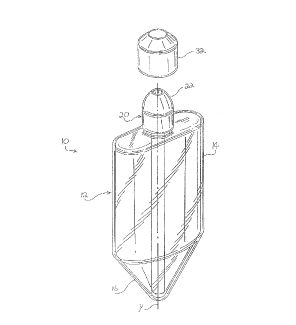
S Referring to the drawings, a device 10 for delivering
and collec~ing fluids is shown in Fig. 1. Device 10
includes a generally, elliptical-shaped container 12 having
resilient walls 14 The walls of the container begin to
converge in the lower portion of the container, resulting
in a bottom 16 having the general configuration of an
inverted, generally elliptical frustum. This frustum is
symmetrical about an axis Y that passes through the
container. Container 12 also includes an opening 18 (shown
in Fig. 3) formed in its upper portion and a nozzle 20
removably secured thereto. Nozzle 20 is preferably secured
to a neck 21 of container 12.
Nozzle 20 preferably includes a dome-shaped lip 22
configured to occlude the entrance to a body cavity and
which facilitates sealing of the nozzle with such entrance
during use. As best shown in Fig. 3, nozzle 20 is formed
with a port 2~ that converges in diameter from Dl at the
apex of lip 22 to Dz at the junction of the port and a
discharge tube 26. Port 24 both facilitates discharge of
solution from the container (i e., by diffusing the
2S discharged solution) and also facilitates collection of the
solution from the body cavity (i.e., by providing a large
diameter opening to guide the returning solution back into
the container)
As shown in Fig. 3, discharge tube 26 has a first end
28 which is connected to nozzle 20, and a second end 30
which extends into and terminates in the lowermost region
of the frustum The internal diameter of the tube, which
CA 02229337 1998-03-09
WO 97/09931 PCTAUS96~14576
establishes the flow path of the solution, communicates
with the innermost portion of the port. As shown, the
tube is preferably formed integral with the nozzle so that
the nozzle and tube may be removed as one unit. of course,
the tube may also be fabricated separate from the nozzle.
Other embodiments, for example, an embodiment in which a
plurality of tubes are employed or an embodiment in which
the tube(s) is formed integral with the walls, are also
contemplated.
When the container is filled to level L1 with fluid,
all of the fluid is held in the frustum of the container
while such container is maintained in a generally verticle
orientation (as depicted in Fig. 3). It is readily
apparent from the figures that the depth of the fluid (as
measured in the ~rustum) will be greatest along axis Y.
This is true even as the total level of fluid in the
container is depleted because the converging walls of
bottom 16 tend to pool the fluid at the central (or
deepest) portion of the frustum. Other design structures,
in which the fluid is also pooled at the first end of the
discharge tube, are also contemplated.
Accordingly, it is possible, through the design of the
present invention, to discharge substantially all of the
solution in the container (i.e., until the solution reaches
L2), while simultaneously maintaining a fluid seal at end
30 of discharge tube 26. It is desirable to maintain this
fluid seal to maximize the pressure differential created by
alternately squeezing anà releasing the walls of the
container. Particularly, the positive pressure created ~y
~0 squeezing the walls of the container propels the solution
out the container, while the negative pressure created when
the walls are released draws the solution back into the
container.
,
CA 02229337 1998-03-09
W O 97/09931 PCTrUS96/14576
--10--
~s described, device 10 is pre~erably ~abricated
from a resilient material (e g , Plastic or rubber ) tllat
allows compression of the container This compression of
the container forces fluid from the frustum of the
container into end 30 o~ the discharge tube, t~lrougn the
discharge tube, and out through port 24 of the nozzle
Preferably, the material employed to fabricate the
container exhibits elastic memory such that tlle contziner
will return to its original configuration once the
compression force is removed therefrom In a preferred
embodiment of the present invention, the container is
fabricated from a transparent material which allows viewing
of the solution contained therein.
Device 10 may include a cover 32 (shown in Fig 1)
for placement over nozzle 20 when the device is not in use.
Device 10 may also include a closure cap 34 (shown in Fig.
8) for sealing the container following the sampling
procedure and removal of the nozzle and tube unit
In an alternative em~odiment of the present invention,
the nozzler i.e., nozzle 20' shown in ~ig ~, is for.-l.ed
with a pressure relief groove 36. Relief groove 36 is
formed~in nozzle 20~ to allow use of the present invention
in applications wherein the creation o~ large pressure
difrerentials is undesirable, such as collecting a specimen
from the ear canal or delivering medication to the ez~
canal Particularly, the inclusion of the relief groove
allows the device to function in substantially the sz~e
fashion, but without creating pressure differentials of
the same degree in the patient's body cavity
The use of the present invention will now be ex~lained
with reference to Figs 5 to ~ and with reference to a
sampling of the nasopharynx of a patient ~s shown in Fig
5, the container is initially empty prior to use Cover 32
,
CA 02229337 1998-03-09
WO 97~9931 P ~ nUS96~1~576
is removed and container 12 is inverted. The resilient
walls of the container are then compressed, thereby ~orcing
a volume o~ air out of the container.
At this point, the nozzle is submersed in a solution
(see Fig. 6) and the compression force is released from the
container. Once the compression force is released, the
walls (due to the inherent memory of the plastic) return
to their initial configuration, thereby creating a negative
pressure in the container which draws the solution into the
container.
Next, as shown in Fig. 7, the patient's head is tilted
slightly ~orward until the entrance to the nostril is
substantially parallel to a level plane P. The device,
which is maintained in a substantially vertical
orientation, is then positioned under the nostril. The
nozzle of the device is inserted into the nostril until a
seal is formed between the nozzle and the nostril. The
other nostril of the patient is pinched closed.
The resilient walls of the container are then squeezed
to deliver the solution. Specifically, by squeezing the
resilient walls of the container, a positive pressure is
created in the container which forces the fluid from the
frustum, into the discharge tube, and out of the nozzle.
The container is squeezed until the level of solution in
the container drops to L2. At this point, substantially
all of the solution has been delivered to the nasopharynx.
Further, because the fluid seal has been maintained at end
30 of the discharge tube and because the seal between the
nostril and nozzle has been maintained, a negative pressure
will be created when the walls of the container are
~ released
CA 02229337 1998-03-09
W O 97/09931 PCT~US96/14576
-12-
Accordingly, after an appropriate period of time,
the physician releases the walls of the container to allow
the walls to return to their initial configuration. As the
walls expand outward, a negative pressure is developed in
the bottle The combination of gravity and negative
pressure substantially dra~.ls the entire volume of dispensed
solution back into the container The design of port 24
also facilitates this collection process.
Once the solution is collected in the container,
the discharge and collection process can be repeated.
After the sampling procedure is completed, the nozzle
and attached transfer tube may be removed and discarded,
securing cap 34 placed over the opening (see Fig. 8),
and the container and entire contents forwarded to an
appropriate facility for analysis.
The same procedure is employed to sample other body
cavities such as the ear, vagina or rectum. As mentioned,
the use of device lO to collect samples from such cavities
provides more accurate specimens and accomplishes the
sampling procedure in a less invasive manner than the prior
art devices and techniq~es. A similar discharge and
collection procedure may also be employed to cleanse an
internal body surface. As is apparent from the above-
description, the fluid seal is eliminated when device 10
is inverted Once inverted, the device can be readily
employed to aspirate pooled solutions.
Further, the above-described procedure is particularly
well-suited for delivery of medicine to a body cavity
(e.g., the nasopharynx, ear, eye, vagina, rectum). As
mentioned, certain medical procedures require the
application and prompt removal of medicine to and from a
body cavity (e.g., the treatment of a cancer of the nasal
passage) The present invention allows a physician to
CA 02229337 1998-03-09
W O 97~09931 PCTAJS96/14576
consistently accomplish this task. Similarly, the present
invention allows a physician to accurately deliver a known
quantity of medicine to a body cavity, particularly in
those medical procedures which require that a predetermined
amount of medicine be applied to the body surface.
Thus, while there have been described what are
presently believed to be the preferred embodiments o.
the invention, those skilled in the art will realize that
various changes and modifications may be made to the
invention without departing from the spirit of the
invention, and it is intended to claim all such changes and
modifications which fall within the scope of the invention