Note: Descriptions are shown in the official language in which they were submitted.
CA 02229393 2001-05-03
EYE GLASS CLEANING MACHINE
by
Ken Maines, of 40 Hidden Vale CI. NW, Calgary, AB T3A 5C8, Canada.
BACKGROUND
Eye glass cleaning machines are known to use fluids and hot air to
clean and dry a pair of eye glasses. However, many such machiries are
not adapted for home use, since they are too costly, too bulky or otherwise
unsuited for mass-production for the home market.
A common problem of known eye glass cleaning machines is a
failure to adequately facilitate the addition and removal of the fluids needed
to clean the eye glasses. In some machines, a funnel or similar tool is
required to pour cleaner into a port having a threaded cap closure.
Separate and easily assessable storage tanks for cleaning, rinsing and
waste fluids are rare or unknown. In many machines the prem;xing of fluids
is required, since separate tanks are not provided and the machine does
not provide the necessary means to accomplish the task in an automated
manner.
A common problem found in most if not all known machines is that
of water spotting on the eye glass lenses due to trace minerals present in
water. In some geographic areas this can be particularly troublesome. A
related problem concerns the tendency of water jets to foul and plug due
to mineral deposits.
A further problem common to many known machines is that only the
lenses of the eye glasses are washed, and the arms are not cleaned. In
many machines where the arms are cleaned the machine is quite bulky,
1
CA 02229393 1998-02-11
and nc~t suited for home use.
,A still further problem common to several machines is the
dependence on brushes or other frictional means to clean the lenses which
may over time cause damage.
SUMMARY
The present invention is directed to an apparatus that solves the
above problems. A novel eye glass cleaning machine provides structures
consisi:ent with the need for better and more convenient fluid handling, less
susceptibility of eye glass lens spotting due to water deposits, and greater
ability of the machine to self-clean.
The eye glass cleaning machine of a version of the present invention
providEa some or all of the following structures:
(a;~ An enclosure provides a base having a oval bowl beneath a
transparent oval top. Eye glasses are carried above a bowl and
beneath the oval top by the pair of adjustable clips which
secure the hinge portions of the eye glass frames. Spray
nozzles, located at intervals about the bowl, are suitable for
spraying either cleaning fluid, rinse water or drying air at the
glasses.
(b;) Separate soap, water and waste tanks are carried within the
enclosure below the bowl, and may be filled by pouring liquid
into the bowl. A drain valve carried at the base of the bowl
directs the fluid draining from the bowl into one of the three
tanks. Heating elements in the water and cleaning fluid tanks
allow the contents of these tanks to be heated.
(c;i A fluid pump, having input from a solenoid valve which selects
2
CA 02229393 1998-02-11
either the cleaning fluid or water rinse tanks, applies pressurized
liquid to the nozzle elements.
(d) An air pump provides pressurized air to the nozzles, during a
drying cycle.
(e) Electronics, including a microcontroller and switching devices,
provides control over the heating elements, an operational
indicator LED, the fluid pump and the air-pump. The electronics
controls various cycles. During a warming cycle fluids in the
tanks are warmed, prior to use. A wash cycle activates the
pump, thereby delivering the cleaning fluid through the nozzles
and onto the eye glasses. A rinse cycle activates the solenoid
valve, thereby causing rinse water rather than cleaning fluid to
be delivered to the nozzles. A drying cycle turns off the fluid
pump and turns on the air pump, delivering drying air to the
nozzles which dries the lenses in a spot-free manner.
It is therefore a primary advantage of the present invention to provide
a novel eye glass cleaning machine that eliminates the need to mix fluids
prior to pouring them into the machine.
Another advantage of the present invention is to provide a novel eye
glass cleaning machine that is compact, inexpensive, does not use frictional
brushes and that washes both the lenses and the arms of the glasses.
Another advantage of the present invention is to provide a novel eye
glass cleaning machine that provides a novel two- or three-way drain valve
3
CA 02229393 1998-02-11
that allows easy input of fluids into the fluid tanks of the machine.
A still further advantage of the present invention is to provide a novel
eye glass cleaning machine that reduces the problem of water spotting of
the lenses and water deposit and soap build up inside the cleaning
machine.
DRAWI NGS
These and other features, aspects, and advantages of the present
invention will become better understood with regard to the following
description, appended claims, and accompanying drawings where:
FIG. 1 is a side orthographic view of a version of the eye glass cleaning
machine of the invention, showing the transparent oval top, the fluid
level indicators, the switch, the operation light and the waste tank
drain plug;
FIG. 2 is a top orthographic view of the eye glass cleaning machine of FIG.
1, having a pair of eye glasses installed;
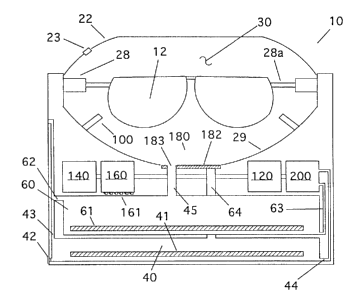
FIG. 3 is a side cross-sectional view of a first version of the invention,
having a rinse water tank and combined function cleaning fluid and
waste containment tank;
FIG. 4 is a side cross-sectional view of a second version of the invention
having separate cleaning fluid, rinse water and waste tanks;
FIG. 5 is a somewhat diagrammatic view of a version of the electronics
having a microcontroller chip having switching and timing
functionality controlling an operation light, heating elements, a pump,
4
CA 02229393 1998-02-11
a solenoid valve controlling the input to the pump and an air pump;
FIG. 6a. is a top orthographic view of a two-way drain valve associated with
l:he version of the invention of FIG. 3; and
FIG. 6k> is a top orthographic view of a three-way drain valve associated
with the version of the invention of FIG. 4.
DESCRIPTION
Referring in particular to the cross-sectional views of FIGS. 3 and 4,
two similar representative versions of an eye glass cleaning machine 10
constructed in accordance with the principles of the invention are seen.
The invention resides not in any one of these features per se, but rather in
the particular combination of all of them herein disclosed and claimed and
it is distinguished from the prior art in this particular combination of all
of
its structures for the functions specified.
In each version of the invention an enclosure 20 providing a base 21
having a bowl 29 forming an eye glass cavity 30 supports a pair of eye
glasses 11 to be cleaned by means of adjustable clips 28. In the first
version, seen in FIG. 3, a heated cleaning fluid and waste fluid tank 40 and
a rinse water tank 60 are filled by a two-way drain valve 180 at the base of
the bowl 29. In the second version, seen in FIG. 4, a heated cleaning fluid
tank 50, a heated rinse water tank 60 and a waste tank 70 are filled by a
three-way drain valve 181. In both versions of the invention, an electronics
card 220 controls the operation of a fluid pump 120, air pump 140, a
solenoid valve 200, which determines from which tank (cleaning fluid or
rinse water) the fluid supplied to spray nozzles 100 will be taken, and other
functions.
Referring in particular to FIGS. 1, 3 and 4, the enclosure 20 is seen.
5
CA 02229393 1998-02-11
The enclosure provides a base 21 supporting an oval top 22. In the
preferred version of the invention, the base and oval top are made of
plastic, and the top is transparent, thereby allowing the user to view the
cleaning process. An air vent 23 in the oval top allows air to be exhausted
during the drying cycle, as will be discussed below. A switch opening 24
allows the user to activate the on-off switch, thereby starting the cleaning
cycle. Cleaning fluid, rinse water and waste tank gauges 25, 26, 27 provide
a transparent view port adjacent to graduated indicators that allow the user
to view the transparent tanks directly to determine their contents.
Adjustable clips 28 allow the user to mount and support a pair of
glasses within an eye glass cavity 30 over the bowl 29. The clips 28 are
typically of an alligator type that grip the hinges 14 of the eye glasses with
arms 13 folded, as seen in FIG. 2. A jaw 28a is supported by the base
28b. The jaw may be rotated within the base and extended or retracted
somewhat to accommodate differing eye glass sizes.
In the first version of the invention, seen in FIG. 3, a cleaning fluid
and waste containment tank 40 contains cleaning fluid at the beginning of
the cleaning cycle, and a combination of cleaning fluid, dirt and rinse water
at the end of the cleaning cycle. The cleaning fluid/waste tank 40 provides
an electric heating element 41 that is suitable for submersion in fluid. A
drain plug 42 allows waste fluid to be drained after the cycle is over. A
dispensing tube 44 draws fluid from the bottom of the tank 40, and carries
the fluid to an input of the solenoid valve 200. Air enters or leaves through
air vent 43, to relieve pressure, as fluid enters or leaves the tank. A fill
port
45 is in communication with the two-way drain valve 180. As a result, liquid
in the bowl 29 will drain into the tank 40, if the valve 180 is opened. The
6
CA 02229393 1998-02-11
cleaning fluid is therefore filled in this manner, and waste resulting from
spraying the eye glasses returns in this manner.
The tanks 40, 50, 60, 70 are typically made of transparent or
semi-transparent plastic, so that the fluid level may be determined by
observation of the tank through gauge 25.
A rinse fluid or water tank 60 is seen in both FIGS. 3 and 4, and is
common to both versions of the invention. In the preferred embodiment,
the rinse fluid used is water, but could alternatively be alcohol or some
other fluid. The water tank 60 provides a heating element 61 similar to the
heating element 41 discussed above. A dispensing tube 63 draws fluid
from the bottom of the tank 60, and carries the fluid to an input of the
solenoid valve 200. The water tank also provides an air vent 62, which
allows air to enter the tank as rinse water is removed. A fill port 64 is in
communication with the two-way drain valve 180 or the three-way drain
valve 181, and liquid in the bowl 29 will drain into the tank 60, if the valve
180 is opened. The water tank is therefore filled in this manner.
SOLENOID VALVE. A solenoid valve 200 provides two inputs and
a single fluid output. In a first version of the invention, the solenoid valve
has input from the dispensing tube 44 of the combined cleaning fluid and
waste tank 40 and from the dispensing tube 63 of the rinse fluid tank 60.
In a second version of the invention, the solenoid valve has input from the
dispensing tube 53 of the cleaning fluid tank 50 and the dispensing tube
63 of the rinse fluid tank 60. The valve is movable between two settings,
or states, in which either of the two inputs is in communication with the
output. The output tube 201 is typically connected to the fluid pump 120.
The setting of the valve is controlled by the electronics, as will be seen,
7
CA 02229393 2001-05-03
which provides an electrical input to the valve 200.
A fluid pump 120 pumps fluid from the solenoid valve 200 to a distribution box
160. In the preferred embodiment of the invention, the pump 120 is similar in
construction to the pumps used in WATER PIC (trademark) type dental cleaning
tools, but may be larger in capacity to enable it to supply pressurized fluid
to a
distribution box 160, from which six spray nozzles 100 may be supplied
simultaneously.
The distribution box 160 functions to eliminate the tendency of nozzles nearer
the pump from having greater pressure and therefore having a more powerful
spray
than nozzles further from the pump. In the preferred embodiment, the input to
the
distribution box is from the fluid pump 120 and the air pump 140, and separate
output tubes 161 from the distribution box connect each of the nozzles 100.
typically, the output tubes 161 exit from the bottom of the distribution box,
so that air
forced into the distribution box by the air pump will flush any fluid out. The
distribution box is typically centrally located within the enclosure, and is
formed of an
air-tight construction.
An air pump 140 forces ambient air into the distribution box 160, where it
exits
through output tubes 161 and nozzles 100. Air speeds the drying process in
part by
blowing water from the lenses by force, thereby helping to eliminate spotting
by
removing the water containing trace minerals before the water has a chance to
evaporate. Additionally, the forced air tends to speed evaporative drying of
small
amounts of remaining water. As a result, in the preferred embodiment, the air
exiting from air pump 140 is typically not heated, as this would result in a
greater
tendency for the water droplets to dry while on the lenses. After exiting from
the
s
CA 02229393 1998-02-11
nozzles, water-vapor carrying air may exit from air vent 23 on the oval top
22 of the enclosure 20. The movement of air through the distribution box
160 and nozzles 100 tends to remove water from those structures, thereby
preventing water deposit buildup.
As seen in FIGS. 6a and 6b, a two-way drain valve 180 and a
three-way drain valve 181 allows fluid to drain from the bowl 29 into any of
the tanks 40, 50, 60, 70. The drain valves 180, 181 provide a rotatable
plate valve 182 having a hole 183 that may be rotated to allow drainage
into a fill port 45, 54, 64, 73. In the first version of the invention, having
a
combined cleaning fluid/waste tank 40 and a rinse water tank 60, only two
fill ports would be connected to the base of the bowl 29, a waste/cleaning
fluid fill port 45 and a rinse water input fill port 64. In the second version
of the invention, three pipes would be provided, a water input fill port 64,
a waste fill port 73 and a cleaning fluid fill port 54.
By rotating the valve plate 182, the hole 183 in the valve plate may
be lined up with any fill port, or with no fill port. When the hole 183 in the
plate 182 is lined up with no fill port, the tanks are all sealed. This is
advantageous when moving or storing the machine.
As seen in FIGS. 1 and 5, an electronics card 220 controls the
functionality of the eye glass cleaning machine. An ac plug having an
attached direct current power converter 224, of a type that is well-known
and commercially available provides a direct current power line 236 to the
unit. -fhe current provided is typically low voltage do current, which is
consistent with the safe electrical practices.
A microcontroller 221 provides the timer and switching functionality
required. A pushbutton activation switch 223 is connected to an input port
9
CA 02229393 1998-02-11
line 235 of the microprocessor, and activates the cleaning cycle. An output
line 230 from the microcontroller controls the switching device 227 for the
pump 120. An output line 231 from the microcontroller controls the
switching device 228 for the air pump 140. An output line 232 from the
microcontroller controls the indicator LED 222. An output line 233 from the
microcontroller controls the switching device 225 for the water heater
element 61. An output line 234 from the microcontroller controls the
switching device 226 for the cleaning fluid heating element 41, 51. The
switching devices may be power transistors, TRIACS or relay type devices.
When switched on, the switching device applies the do voltage potential
229 to the connected device.
In the second version of the invention, a separate cleaning fluid tank
50 and waste tank 70 allows the eye glass cleaning machine to be used
multiple times without adding additional cleaning fluid, since the waste fluid
from the cleaning operation is not put into the cleaning fluid tank, but into
a separate waste tank. As a result, a three-way drain valve 181 is used, as
seen in FIG. 4. Fill ports 54, 73 are in communication with the three-way
drain valve 181, and liquid in the bowl 29 will drain into the tanks 50 or 70,
depending on the state of the valve 181. The cleaning fluid tank 50 is
therefore filled in this manner. The cleaning fluid tank 50 provides a
heating element 51 and an air vent 52. The waste tank 70 provides a drain
plug 71 and an air vent 72. A dispensing tube 53 draws fluid from the
bottom of the cleaning fluid tank 50, and carries the fluid to an input of the
solenoid valve 200.
To use the eye glass cleaning machine of the invention, the eye
1o
CA 02229393 1998-02-11
glasses 11 are first attached to the adjustable clips 28. The jaw 28a of
each clips is rotated about its base, as needed, and then attached to the
hinges 14 of the arms 13 of the glasses.
The wash cycle is initiated by the activation switch 223. An optional
delay cycle may initiate the wash cycle. Following the delay cycle, the
microprocessor turns on the heating elements 41, 51, 61, depending of the
version of the invention. The heating elements increase the temperature of
the cleaning fluid and rinse water, which improves cleaning and drying
efficiency. As seen in the circuit schematic of FIG. 3, the current required
to activate the heating elements, pump and air pump is greater than what
can be provided by the microcontroller; therefore the microcontroller
activates a relay or other switching device which applies current to these
devices. Following the heating cycle, the current to the heating elements
is turned off. The microcontroller then activates the solenoid, causing the
solenoid to cause the associated valve to direct fluid flow from the cleaning
fluid tank 40, 50. The microcontroller then turns on the fluid pump 120,
causing cleaning solution to flow from the cleaning fluid tank, through the
solenoid valve, through the distribution box 160, through the spray nozzles
100 and onto the lenses 12 and other parts of the eye glasses 11. After a
prescribed period, which may easily be programmed into the
microcontroller, the pump is shut off, the state of the solenoid valve is
reversed, connecting the rinse water tank 60 to the pump, and the pump
turned on. This rinses the glasses and removes cleaning fluid from the
distribution box and nozzles. After a further prescribed period the pump is
again turned off by the microcontraller. The air pump 140 is then turned
on. Air from the air pump is forced into the distribution box, where it forces
11
CA 02229393 1998-02-11
out the water from the rinse cycle. Air then is expelled from the nozzles
100, causing it to blow-dry the eye glasses.
The previously described versions of the present invention have
many advantages, including a primary advantage of providing a novel eye
glass cleaning machine that eliminates the need to mix fluids prior to
pouring them into the machine.
Another advantage of the present invention is to provide a novel eye
glass cleaning machine that is compact, inexpensive, does not use frictional
brushes and that washes both the lenses and the arms of the glasses.
Another advantage of the present invention is to provide a novel eye
glass cleaning machine that provides a novel two- or three-way drain valve
that allows easy input of fluids into the fluid tanks of the machine.
A still further advantage of the present invention is to provide a novel
eye glass cleaning machine that reduces the problem of water spotting of
the lenses and water deposit and soap build up inside the cleaning
machine.
Although the present invention has been described in considerable
detail and with reference to certain preferred versions, other versions are
possible. For example, two pumps could be used, one for pumping
cleaning fluid and one for pumping rinse water. The location of the pumps
could also be altered, for example the pumps could be either before or
after the solenoid valve. Similarly, two solenoid valves could be used, one
regulating the cleaning fluid leaving the cleaning fluid tank and one
12
CA 02229393 1998-02-11
regulating the water leaving the rinse water tank. Therefore, the spirit and
scope of the appended claims should not be limited to the description of
the preferred versions disclosed.
13