Language selection

Search

Patent 2229424 Summary

Third-party information liability

Some of the information on this Web page has been provided by external sources. The Government of Canada is not responsible for the accuracy, reliability or currency of the information supplied by external sources. Users wishing to rely upon this information should consult directly with the source of the information. Content provided by external sources is not subject to official languages, privacy and accessibility requirements.

Claims and Abstract availability

Any discrepancies in the text and image of the Claims and Abstract are due to differing posting times. Text of the Claims and Abstract are posted:

  • At the time the application is open to public inspection;
  • At the time of issue of the patent (grant).
(12) Patent: (11) CA 2229424
(54) English Title: CIRCUIT TO IMPROVE TRANSDUCER SEPARATION IN HANDSFREE TELEPHONE
(54) French Title: CIRCUIT VISANT A AMELIORER LA SEPARATION DU TRANSDUCTEUR D'UN TELEPHONE MAINS LIBRES
Status: Deemed expired
Bibliographic Data
(51) International Patent Classification (IPC):
  • H04M 1/20 (2006.01)
  • H04M 1/19 (2006.01)
  • H04M 1/60 (2006.01)
(72) Inventors :
  • MCLEOD, ROB (Canada)
(73) Owners :
  • MITEL NETWORKS CORPORATION (Canada)
(71) Applicants :
  • MITEL CORPORATION (Canada)
(74) Agent: SIM & MCBURNEY
(74) Associate agent:
(45) Issued: 2001-04-24
(22) Filed Date: 1998-02-13
(41) Open to Public Inspection: 1998-08-18
Examination requested: 1998-02-13
Availability of licence: N/A
(25) Language of filing: English

Patent Cooperation Treaty (PCT): No

(30) Application Priority Data:
Application No. Country/Territory Date
08/802,001 United States of America 1997-02-18

Abstracts

English Abstract


In a device having a sound source within an enclosure and a first microphone
for picking up sounds outside the enclosure, a system for improving acoustic
separation between the sound source and first microphone comprising an additional
microphone located approximately equidistant from the sound as the first microphone
for picking up sounds within the enclosure, and a circuit connected to the firstmicrophone and the additional microphone for subtracting the sounds within the
enclosure from the sounds outside the enclosure.


French Abstract

Dans un dispositif ayant une source sonore à l'intérieur d'un boîtier ainsi qu'un premier microphone destiné à capter des sons à l'extérieur du boîtier, un système permet d'améliorer la séparation acoustique entre la source sonore et le premier microphone. Ce système comprend un microphone supplémentaire situé à distance à peu près égale du son comme le premier microphone, afin de capter les sons à l'intérieur du boîtier, ainsi qu'un circuit relié au premier microphone et au microphone supplémentaire pour soustraire les sons à l'intérieur du boîtier des sons à l'extérieur du boîtier.

Claims

Note: Claims are shown in the official language in which they were submitted.


6
Claims:

1. In a device having a sound source within an enclosure and a first
microphone
for picking up sounds outside said enclosure, a system for improving acoustic
separation between said sound source and said first microphone, comprising an
additional microphone located approximately equidistant from said sound source
as
said first microphone for picking up sounds within said enclosure due to said
sound
source, and a circuit connected to said first microphone and said additional
microphone for subtracting said sounds within said enclosure from said sounds
outside said enclosure, wherein said enclosure has an opening directly
corresponding
to said first microphone but does not have an opening directly corresponding
to said
additional microphone.
2. The system of claim 1, wherein said circuit is characterized by an
optimized
frequency response in a band around the resonance frequency of said sound
source.
3. The system of claim 1, wherein said circuit includes an amplifier for
amplifying said sounds outside said enclosure by a first gain and for
amplifying said
sounds inside said enclosure by a second gain, wherein said first gain and
said second
gain are chosen such that sound from said sound source is canceled by said
circuit.
4. The system of claim 1, 2 or 3 wherein said device is a speakerphone, said
first
microphone is a voice microphone, said sound source is a speaker and said
additional
microphone is acoustically matched to said voice microphone.
5. A speakerphone apparatus having improved acoustic separation between a
speaker and a microphone, comprising:
a speaker within a housing, the housing having an opening adjacent said
speaker;
a speaker microphone within the housing to detect sound internal to the
housing due to said speaker's output, the housing not having an opening
directly
corresponding to said speaker microphone;


6a

a voice microphone within the housing but receiving sound external to the
housing via an opening in the housing adjacent said voice microphone; and
a subtraction circuit coupled to said voice microphone and said speaker
microphone, said subtraction circuit subtracts the sound internal to the
housing
detected by said speaker microphone from the sound external to the housing
detected
by said voice microphone.
6. A speakerphone apparatus as recited in claim 5, wherein said speaker
microphone and said voice microphone are positioned within the housing
approximately equidistant from said speaker.
7. A speakerphone apparatus as recited in claim 5, wherein sound emitted from
said speaker is detected by said speaker microphone and said voice microphone
substantially in phase.
8. A speakerphone apparatus as recited in claim 5, wherein said subtraction
circuit comprises:
an amplifier for amplifying sound from said speaker microphone by a first
gain and for amplifying sound from said voice microphone by a second gain, the
first
gain being less than the second gain.
9. A speakerphone apparatus as recited in claim 8 wherein sound emitted from
said speaker is detected by said speaker microphone and said voice microphone
substantially in phase.
10. A speakerphone apparatus as recited in claim 5, wherein said speaker
microphone and said voice microphone are acoustically matched.
11. A speakerphone apparatus as recited in claim 5, wherein said subtraction
circuit has an optimized frequency response in a band around the resonance
frequency
of said speaker.

Description

Note: Descriptions are shown in the official language in which they were submitted.


CA 02229424 1998-02-13


Circuit to Improve Transducer Separation in Handsfree Telephone

Field of the Invention

The present invention relates in general to devices incorporating a microphone
and a sound or noise source in a single enclosure, such as handsfree or speakerphone
systems, telephones, and more particularly to a circuit for improved separation
between microphone and speaker.

0 ~ k~round of the Invention

It is a requirement of a handsfree or speakerphone design to provide sufficient
acoustic separation between the microphone and the speaker. For systems where the
microphone and speaker are to be in the same enclosure this requirement can present a
challenge. This is a problem for both half-duplex and full-duplex systems, where the
acoustic coupling of the speaker output to the microphone input must be minimi7ed to
m~int~in stability in the system.

One component of this coupling is mechanical (i.e. through the structure of
the enclosure). The other component is transmitted via air. This coupling is usually
greater at or about the resonance frequency of the speaker.

Much acoustic, industrial and mechanical design effort can be expended in
design of the enclosure in order to minimi7.~ the separation, but this does not usually
2s occur because of cost and the limited time within which to supply a product to
market. Sometimes the acoustic aspect of an enclosure are dealt with after otheraspects of the enclosure are fin~li7e-1, thus reducing the opportunity to minimi7e
couplmg.

The use of unidirectional microphones can reduce coupling, but it is difficult
to design unidirectional microphones into a telephone type of enclosure because they
require the sound to be present at the front and back of the microphone. Also, a

CA 02229424 1998-02-13


unidirectional microphone restricts the user to one position in front of the microphone.

It is an object of an aspect of the present invention to provide a simple and
inexpensive means for providing improved separation between the speaker and
s microphone in a handsfree or speakerphone system where both transducers are located
in the same enclosure.

Summarv of the Invention

o According to the present invention, improved acoustic separation is provided
in an handsfree or speakerphone enclosure by means of providing a second
inexpensive omnidirectional microphone (referred to herein as the speaker
microphone) which is placed inside the enclosure to primarily pick up sound from the
speaker, and a circuit for subtracting this sound from the sound picked up by the voice
microphor e which is positioned to pick up sound occurr.ng outside of the enclosure.

Brief Introduction to the Drawin~s

A detailed description of the pr~relled embodiment is provided herein below,
with reference to the following drawings, in which:

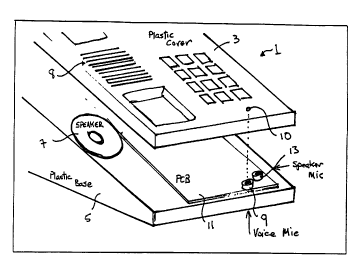
Figure 1 shows placement of a speaker microphone within a handsfree
telephone set relative to the speaker and the voice microphone, according to an aspect
of the invention; and
Figure 2 is a schematic diagram of a circuit for subtracting the sound picked
up by the speaker microphone from the sound picked up by the voice microphone.

CA 02229424 1998-02-13


Detailed De- i~lion of the Preferred Embodiment

Turning to Figure 1, a handsfree telephone set enclosure 1 is shown
comprising a plastic cover 3 mounted to a plastic base 5. A speaker 7 is provided
5 within the enclosure 1 for co,l"l,u"icating sound to a user through a grill 8 in the
plastic cover 3. To facilitate handsfree telephone communications in conjunction with
the speaker 7, a voice microphone 9 is provided in the enclosure l for picking up
sounds via an aperture 10 in the plastic cover 3. A printed circuit board 1 l is provided
in the base S for housing the microphone 9 and additional ch~;uill.y required for
o operation of the telephone.

According to the present invention, a speaker microphone 13 is inside the
enclosure 1 for picking up the sound emitted by the speaker 7. The enclosure 1
sigIuficantly attenuates sounds from outside of the enclosure, such that the sounds
5 picked up by the speaker microphone 13 may be subtracted from the sounds picked up
by the voice microphone 9 which picks up sounds from outside of the enclosure,
including sounds emitted by the speaker 7. As shown in Figure 1, the microphones 9
and 13 are positioned so as to be equidistant from the speaker 7, and are mechanically
connected to the enclosure 1 in a similar fashion. Preferably, the microphones 9 and
20 13 are the same model of microphone but need not be perfectly matched, provided
that the sounds from speaker 7 are picked up by both microphones 9 and 13
subst~nti~lly in phase.

A subtracting circuit is illustrated in Figure 2, according to one embodiment of25 the present invention. The subtracting circuit is preferably designed for optimum
performance in the frequency band in which the voice microphone 9 has maximum
coupling to speaker 7 (i.e. typically a band around the resonance frequency of speaker
7). Each of the voice microphone and speaker microphone 13 are connected to a
respective input of an operational amplifier 15 via pull-up resistors 17 and 19, each
30 having a predetennined resistance (Rbias) and connected to a source of bias voltage
(Vbias). Voice microphone 9 is connected to an inverting input of amplifier 15 via a

CA 02229424 1998-02-13


seriesconnectionofcapacitor21 andresistor23. Speakermicrophone 13 is
connected to a non-inverting input of amplifier 15 via a series connection of capacitor
25 and resistor 27. A feeclback resislor 29 connects the output of amplifier 15 to the
inverting input thereof, and a resistor 31 connects the non~inverting input of amplifier
15 to ground.

The gains and poles for the signal paths in the circuit embodiment of Figure 2
are useful for a situation where the microphone outputs are in phase and the output of
speaker microphone 13 is twice that of voice microphone 9. Specifically, Each ofo resistors 23, 29 and 31 has resistance "R", capacitor 25 has a capacitance of"C" and
capacitor 21 has a capacitance of "4C"', while resistor 27 has a resistance of "3R".
The gain of the voice microphone 9 is -R/R=l, while the gain of the speaker
microphone 13 is R/(R+3R)x(l+R/R)=1/2. Since the frequency response is the same
for both microphones, in-phase signals the speaker sounds picked up by voice
15 microphone 9 are canceled by the speaker sounds picked up by the speaker
microphone 13, leaving only the desired voice sounds at the output of the circuit
(Vout).

Testing of the system according to the present invention has resulted in
20 measured cancellation of 20dB with matched microphones and 12 dB with 2.5 dB
mi~m~tt~h between the microphones 9 and 13.

Alternatives and modifications of the invention are possible. All such
embodiments and modifications are believed to be within the sphere and scope of the
25 invention as set forth in the claims appended hereto. For example, the principles of
the present invention may be implemented in digital form (e.g. via a digital signal
processor (DSP)). Moreover, it is contemplated that the principles of the invention
may be employed in any device co~ti~ g a microphone and a sound or noise source
within a single enclosure, such as video conferencing systems, cellular hands free
30 devices and portable tape machines. [n the case of a tape machine, the source is noise

CA 02229424 1998-02-13


and vibration from the tape drive, whereas video conferencing and cellular handsfree
phones are applications of the speaker phone technology discussed in connection with
the preferred embodiment.

Representative Drawing
A single figure which represents the drawing illustrating the invention.
Administrative Status

For a clearer understanding of the status of the application/patent presented on this page, the site Disclaimer , as well as the definitions for Patent , Administrative Status , Maintenance Fee  and Payment History  should be consulted.

Administrative Status

Title Date
Forecasted Issue Date 2001-04-24
(22) Filed 1998-02-13
Examination Requested 1998-02-13
(41) Open to Public Inspection 1998-08-18
(45) Issued 2001-04-24
Deemed Expired 2006-02-13

Abandonment History

There is no abandonment history.

Payment History

Fee Type Anniversary Year Due Date Amount Paid Paid Date
Request for Examination $400.00 1998-02-13
Registration of a document - section 124 $100.00 1998-02-13
Application Fee $300.00 1998-02-13
Maintenance Fee - Application - New Act 2 2000-02-14 $100.00 2000-02-03
Final Fee $300.00 2001-01-23
Maintenance Fee - Application - New Act 3 2001-02-13 $100.00 2001-02-02
Registration of a document - section 124 $50.00 2001-05-04
Maintenance Fee - Patent - New Act 4 2002-02-13 $100.00 2002-01-17
Maintenance Fee - Patent - New Act 5 2003-02-13 $150.00 2003-01-17
Registration of a document - section 124 $100.00 2003-02-07
Maintenance Fee - Patent - New Act 6 2004-02-13 $150.00 2003-12-22
Registration of a document - section 124 $100.00 2005-07-18
Owners on Record

Note: Records showing the ownership history in alphabetical order.

Current Owners on Record
MITEL NETWORKS CORPORATION
Past Owners on Record
MCLEOD, ROB
MITEL CORPORATION
ZARLINK SEMICONDUCTOR INC.
Past Owners that do not appear in the "Owners on Record" listing will appear in other documentation within the application.
Documents

To view selected files, please enter reCAPTCHA code :


To view images, click a link in the Document Description column. To download the documents, select one or more checkboxes in the first column and then click the "Download Selected in PDF format (Zip Archive)" or the "Download Selected as Single PDF" button.

List of published and non-published patent-specific documents on the CPD .

If you have any difficulty accessing content, you can call the Client Service Centre at 1-866-997-1936 or send them an e-mail at CIPO Client Service Centre.


Document
Description 
Date
(yyyy-mm-dd) 
Number of pages   Size of Image (KB) 
Representative Drawing 1998-08-28 1 10
Cover Page 2001-04-11 1 46
Abstract 1998-02-13 1 13
Description 1998-02-13 5 168
Claims 1998-02-13 1 29
Drawings 1998-02-13 2 24
Cover Page 1998-08-28 1 45
Claims 2000-05-29 2 88
Representative Drawing 2001-04-11 1 11
Assignment 1999-02-12 2 86
Assignment 2003-02-07 7 213
Correspondence 2003-03-13 1 2
Assignment 2003-04-29 5 139
Prosecution-Amendment 2000-05-29 4 140
Assignment 2001-05-04 13 780
Assignment 2001-06-13 2 98
Fees 2001-02-02 1 51
Correspondence 2001-04-23 1 23
Correspondence 2001-01-23 1 52
Assignment 1998-02-13 3 97
Correspondence 1998-05-12 1 30
Correspondence 2001-06-13 1 23
Assignment 1999-03-31 1 39
Prosecution-Amendment 2000-01-27 2 3
Fees 2000-02-03 1 51
Assignment 2005-07-18 42 3,905