Note: Descriptions are shown in the official language in which they were submitted.
CA 02229630 1998-03-16
~lETHOD AND APP.~R~TUS FOR ANNOTAT~ON OF MEDICAL
li~lAGERY TO FACILITATE P~TIENT IDENTIFICATION. DI~GNOSIS.
AND TREATi~IENT
This application is based on provisional applications No. 60!027.777 filed
July ~9, 1996 No. 60i0~8 385 filed October 1~. 1996 and No. 60/078,387 filed
October 15. 1996.
BACKGRO~TND OF THE rN~/~NTIO~
This invention relates generally to the field of image recognition and
processing and specifically to methods and systems for identif~ing diagnosing, and
treating people based on thermal minutiae ~ithin a person s body, primarily the
fac e.
Improved methods for automated access control and surveillance are vital
to ensure the continued security of nuclear ~veapon storage facilities as well as
other sensitive or valuable items. Potential threats range from terrorist bombings,
1 ~ insider thefts. and industrial espionage to sabotage bv environmental activists.
There is concern for increased vigilance in the protection of critical strategic assets.
Current technologv being used for access control is not sufficient reliable
secure fast rugged or cost effective for routine unattended operations at high-
security locations. The challenge is to develop systems to secure facilities and~0 personnel from internal and e~ternal threats in a cost effective and timely manner.
Replacing human guards with automated systems can provide a significant cost
savlngs.
The requirement to positivelv identifv each individual seel~ing access to a
facility or to information or services is widespread. Manpower-intensive guard
'5 brigades are deployed at public functions to protect celebrities and at locations
CA 02229630 1998-03-16
where valuable or important items are stored. Guards are used to screen entrantsbased upon reco<Jnizin(J either the person or some credential he carries.
Identification credentials such as photo ID bad<~es and driver's licenses are ~.idel~
usecl for manual identification when cashin~J checl~s or usin(J credit cards. ~Ianual
S chec:kin(7 of such identification cards mav not reco(Jnize cases where the card is
forl1er~ or where the person usin(J it is not the ri(~htful owner of the card. To assist
in solving that problem. more sophisticated identifvin~J characteristics mav be used
on the card, and features ma~ be added to mal;e the card more difficult to
coul?terfeit. The use of biometric characteristics such as finlJerprints. sionatures.
visual descriptions, or photo~Jraphs is becomin(J more common. Such information
can either be readable manuall~ or encoded for readino bv an automated s!!stem.
When the identification system is fullv automated, without a human
attendant. biometric sensors at the access location can compare the characteristics
of a person at the location with the stored characteristics of the person he is
! 5 claimin(J to be. When initiallv issuin~J permission for a person to access abiornetrically-controlled s~ stem or location. his biometric characteristics arerecorded in the s~stem memorv. and also recorded on an identification card. for
later comparison bv the s! stem controller witll his li~ e characteristics.
BRl:EF DESCRIPTIO!~ OF THE PRIOR .~RT
Current biometric identification s~stems include use of inkless fin~erprint
s~vstems (called ~ live scan ' units), retinal scanners. hand (Jeometrv measurin(
deviices, voice recoonition handwritino reco~nition. and facial recoonition sl;stems
~vhich use either visual or infrared cameras. Use of fin~erprints is (Jenerall~
considered the most secure method ior positive identification. Ho~ve~er. when
used in an unattended mode~ fin(Jerprints can be lifted from one location or surface
CA 02229630 1998-03-16
and positioned at another location. Therefore unattended use of fingerprints foridentification at locations requirimJ very hi~lh security is not acceptable. A more
common limitation to widespread use of fin(rerprints for identification is the
requirement for placin~ one or more clean fincTers on a ( lass plate for ima(~in(T bv
S the fin(Terprint reco(Jnition system. This requires that the hands be free andre'latively clean. and that the (~lass plates be maintained intact and clean. The plates
are vulnerable to vandalism. When used for access control at a busv location, there
is a time delay associated with unloadin(T the hands and positionin(T the fin(Ters
pro;perly. Also, users must cooperate with the s!~stem. In certain scenarios of use,
10 cooperation of the subject may be difficult to obtain. Furthermore, many persons
have a reluctance to bein~T fin(Terprinted for an identity card. since they associate
the process ~~ith criminal activities.
Fingerprints traditionall- have been the sole means of positive identification
admissible as evidence in criminal trials in the U.S. Fin(Terprintin(T of criminals,
15 military personnel, persons seekino securit! clearances. and persons applyin(T for
sensitive jobs has been performed f'or man-~ years. The FBI established and
maintained a card file in which eacl- person s fin(Terprints w ere printed by rollino
th finoers first on an ini;ed pad and then on the card. ~luch of the ori~Tinal FBI
fin~Terprint file of rolled prints has now been di(Jitized and made available on-line
20 for computer access. The process of di(fitizin~ the historical files. and theccntinuin~T task of maintainin(J current fin(Terprint files. has cost hundreds of
millions of doilars durin(r the past ten vears alone. Aside from the labor costs of
performino the di_itization and mana(TincT the search tasks throu(Th the database,
si(~nificant R~D has been performed to develop specialized software for comparin(J
25 unknown fin ~erprints a ~ainst the database within a reasonable period of time. and
specialized hardware has been developed to provide rapid response.
CA 02229630 1998-03-16
Inl;less technigues are now ~enerally used to produce a tenprint' card
which substitutes for the former rolled print card. Common inkless techniques
utilize polarized li~ht to illuminate the fin~ers. and li~Jht sensors to ima(~e the li~ht
reflected and refracted t'rom the rid_es. The resultin_ ima~re can be more
5 consistent and hio~her qualih~ than the rolled prints since inconsistencies in the
amount of in'~; applied and in the pressure used to transfer the print to paper are not
a factor.
Automated fin_erprint matchin(!~ techniques have been developed which
rapidly classify an unlinown print and then search throu_h the portion of the
10 database associated ~ ith that class lookincr for a match. Unknown prints may be
from a tenprint'' card or may be latent prints which have been lifted from a crime
scene. A latent print mav include a sizable area of one or more fin<Jers such as on
a water glass or it may include only a portion of one or more finoers such as on a
telephone keypad. Latent prints may be found on top of other latent prints, such as
15 when several people have used the same telephone.
Matchincr techniques often e~tract minutiae points from the prints and then
compare the sets of minutiae rather than compare entire prints. ~ arious
classifications of minutiae types have been proposed by different companies and
aul:horities. .~n e~ample is _iven from the Costello U.S. Patent ~o. 4.947~443. Si~
~0 types of characteristic features'' are presented in this patent, each one relatin~r to a
type of minutia. This fin(Jerprint matchin_ technique references the tvpe,
orientation, and location of each characteristic and each and every other
characteristic. Usin_ this approach~ on the order of 80 to 150 minutia points are
identified in each fin(rerprint. Other fin_erprint minutiae e~traction and matchin
~5 pal:ents produce essentially the same number of minutiae~ ~vith difference in what
fea.tures of the set of minutiae are considered in attempted matchin_ and in how the
CA 02229630 1998-03-16
matchin(~ is performed. In U.S. courts. evidential~ rules have traditionallv required
thiat 16 or more minutia points be found to correspond between two prints in order
for them to be considered to be from the same person. The determination of likelv
matchin(J prints is oenerally assisted or performed entirely by a computer svstem;
S however, the final decree of a match is made bv a fin(Jerprint e~pert, who re~iews
the computer system results.
Matches bet-~ een different prints taken from the same fin(~er are never
perfect, since the fin(~ers are deformable, three-dimensional, connected and jointed
structures which leave two-dimensional prints on surfaces they encounter throu~h10 pressure. The exact an(~les between the finoers and the surfaces. the amount and
direction of pressure. and the effect of movement between the fin(~ers and the
su-rfaces all cause variations in the exact prints produced. Even when prints are
produced by a live scan technique, variation in the li(l~hting hand position, oil or
dust on the finc~ers. use of lotions. and scratches or paper cuts will produce minor
15 variations in the prints produced.
Therefore. the exact number, position and characteristics of minutiae
extracted from two prints mav be different even thou~h thev are produced by the
same fincJer. The challenoe for an automated fin(Jerprint identification system is to
recoC~nize allowable minor variations in actual matchin(J prints ~hile not allowing
~0 variations so wide that mismatches occur. Several .~FIS products are now
commercially offered which provide acceptable accuracv. Local and re~ional
police forces may use smaller databases which contain only the prints of personshistoricallv associated with their areas, rather than relyin~ on federal resources to
search the entire nationwide FBI files. Smaller scale finc~erprint svstem. such as
~S those associated with a system which controls access to an office buildinc~, mav use
the same minutiae matchin(~ techniques.
CA 02229630 1998-03-16
\~ith rolled and live-scan prints. the orientation of each print. and the fin(Jer
to which it corresponds is known. Also. quality checks can be built into the
process such that repeat prints mav be taken to insure qualitv when needed. In the
case of latents. howe~er. the analysis is done after the fact. It is not known which
finger left the print. and the orientation of the fin(rer mav be in doubt when only a
pan:ial print is found. Therefore, matchino of latents is much more difficult than
matchin~J of rolled or live scan prints.
Various minutiae extraction al(gjorithms are used in current fingerprint
identification systems. some of which merely uti]ize the location of the minutia10 points and others of w hich utilize also additional information about the tvpe of
minutia each point represents. For example. simple graph matching techniques canbe used to compare the follow-the-dots vectors ~Jenerated bv connecting the
minutia points in order forced by considering intersections with a spiral from the
centerpoint of the fingerprint. Alternately. the rid(~e angle at each minutia point
] j can be considered and matched along with the coordinates. in a best-fit attempt to
match each unl~nown print to each known print. .~ measure of goodness of fit canthen be computed and used to rank other possible matches.
U.S. patent No. 4~5~5,859 to Bowles teaches a pattern reco~Jnition svstem
which detects line bifurcations and line endin~rs. denoted minutiae. in a pattern of
~0 lines such as are found in a fingerprint. Accordin(r to this reference. the FBI uses
an automatic fin~Jerprint identification svstem entitled F~NDER'' which uses an
optical scan reader. The information is then enhanced to eliminate grays and fill in
gaps in the ridges. A 16x16 increment square window scans the fingerprint, an
increment being a tenth of a millimeter. Thus, a window advances throu~Jh the
~ ~5 fin~;erprint in increments of tenth of millimeter and lool;s for ridges which enter the
window but do not exit it. When such a rid~e is identified. its coordinate ]ocation
CA 02229630 1998-03-16
is s~:ored and the rid(re is analyzed to establish an an_le. theta. of the ridge at the
terrnination. The data are then re-scanned to look for terminations of vallevs
which are ridge bifurcations. The additional coordinates and anc~les of each of the
inverted endin(~ points also are stored.
In latent prints the distances between rido~es of a fin_erprint averao~e 0.4
millimeters but can var~ b-~ a factor of ~ for an~ individual fin_er depending on sl;in
displacement when the fin_er contacts the hard surface normally encountered in
establishin_ a print.
~ ~ known al(~orithm of the National Institute for Standard Technolo(~v can
be used to compare a previously stored electronic image of minutiae coordinate
locations with the minutiae locations identified and stored by the computer.
U.S. Patent No. 5,040.~4 to Hara discloses a fingerprint processing
s~ stem capable of detectin_ a core of a fingerprint image by statisticallv processing
parameters. Hara's invention provides a system to determine a core in the
I 5 fin~erprint image and/or to detect directions and curvatures of rid~es of the
fin(~erprint imag~e prior to detection of the position of the core. This reference
defines minutiae as abrupt endings. bifurcations. and branches.
I~.S. Patent No. 4,790,564 to Larcher teaches a process and apparatus for
matching fingerprints based upon comparing the minutiae of each print in a
~0 database with precomputed vector ima-~es of search minutiae in a search print to be
identified, comparing position and angle. a result of such comparison being a
matching score indicating the probability of a match between the angle of a filepri:nt minutiae and the ancle of precomputed vector ima(~es of the search minutiae.
Over or under-inking of a rolled print can change the apparent type of minutiae
~5 associated with a particular point from one printin(~ to the ne~t. However, not all
colTespondin_ minutiae will appear to chan_e type in the two prints. Therefore.
CA 02229630 1998-03-16
matching for type as ~ ell as for x and y coordinates provides a stricter match
requirement and results in better system accuracy. Larcher assigns higher values to
minutiae whicll match in ~;.y and type.
As Larcher points out~ there are ad~,antages to matching minutiae rather
than the entire image of the fin~erprint in itself. An elementary matching operation
cornprises the comparison of two sets of minutiae~ i.e.~ two sets of points~ each
point having three coordinates x, y, and a. An elementar matcher attempts to
superimpose the two sets of points? in order to count the number of minutiae which
are common to the two fingerprints
Numerous other schemes for matching fin~-~erprints are known. For
example, matchers referred to in Wegstein Technical Note 538 ofthe National
Bureau of Standards (1970) as Ml9, M27~ and M3~, determine whether two
fingerprints come from the same finger b~ computing the densitv of clusters of
points in Dx-Dv space wllere Dx and Dy are the respective differences in x and y15 coordinates for the minutiae of two fingerprints. Experimental results referred to
in this reference indicate that in Dx-Dy space pohlts tend to be located at random
when coming from different fingerprints, uhereas points tend to form a cluster
when coming~ from finoerprints from the same fino~er.
In the Ml9 matcher~ the assumption is made that the transformation needed
20 to superimpose the two sets of minutiae points is a translation onlv. The M27mal:cher is an M l 9 matcher ~~ ith a new scoring function intended to take intoaccount greater translation displacements. The M32 matcher takes into account
small rotations between two fingerprints in the followin(J way: first an l\I27
malcher comparison is made between the two fingerprints; then~ one ofthe two
25 prints is rotated throu_h - V'' degrees from its origillal position and a new 1\127
comparison is made. .~ll to_ether an M32 matcher operation consists of seven
CA 02229630 1998-03-16
M27 comparisons. correspondin~ to the followin_ values for the an_le ~, i.e.
V= -15, -10 -5~ 0 +j +10, +15 decrees.
Minutiae mav be e~ctracted manuallv or automatically. Automatic systems
g enerally require better quality ima_ery. The matcher en_ine must allow for some
de ~ree of inaccuracv or ~ ariabilih~ ~.;ith respect to each of the encoded coordinates
due to human operator bias or precision limitations of automated feature extraction
processes.
Larcher disclosed the use and comparison of type of minutiae, since there is
a _reater match accuracy when ridge endings are compared to ridge endings, and
10 bifi~rcations to bifurcations, as opposed to comparing one ridge ending to one
bifi~rcation.
Other known approaches compare two sets of ima(?~e features points to
det:ermine if they are from two similar objects as disclosed for e~ample in Sclaroff
and Pentland, MIT Media Laboratory, Perceptual Computing Technical Report
15 ~¢304. This reference sug( ests that first a body-centered coordinate frame be
de~ermined for each object, and then an attempt be made to match up the feature
pomts.
Many methods of finding a bodv-centered frame ha~;e been su_gested.
including moment of inertia methods~ symmetry finders~ and polar Fourier
~0 descriptors. These methods àenerally suffer from three difficulties: sampling error,
parameterization error, and non-uniqueness The technique used in Sclaroffand
Pe-ntman disclosure has the limitation that it cannot reliably match largely occluded
or partial objects.
Known techniques associated with fin_erprint minutiae e~;traction and
25 matchino~ can be summarized as follows
First, an unknown fin_er is scanned opticallv;
CA 02229630 1998-03-16
Second. the ima~Je is divided into pi~cels. w here the size of the pixel relatesto the quality of the result desired;
Third. certain pixels are selected as minutiae points:
Fourth. each minutia is assit~ned a vector havin(J ma(~nitude and directional
information in relation to the surrounding characteristics of the fin(Jerprint.
Typically for each fin(Jerprint. there would be a substantial number of minutia
vectors characterizin~ its image:
Fifth, the set of minutia vectors of the unl;nown print are compared by
computer to the set of vectors of known prints; and
Sixth. the comparison results are used to select potential matches and
provide a (roodness of fit indication between the unknown and known prints.
Numerous approaches to reco~nition usin~J visible li~ht ima(Jin~J of faces
have been proposed. ~Iany of them apply standard pattern matchino techniques:
others involve definition of face metrics.
U.S. patent ~io. 4.975.969 to Tal discloses a method and apparatus for
uniquely identifvin(~ individuals by measurement of particular physical
characteristics viewable by the naked eye or b,v ima~in(J in the visible spectrum.
This reference defined facial parameters which are the distances bet~veen
identifiable parameters on the human face. and/or ratios of the facial parameters,
~0 and teaches that the~ can be used to identify an indi~,-idual since the set of
parameters for each individual is unique.
CA 02229630 1998-03-16
Tal's approach utilizes visible features on the face~ and therefore cannot be
relied upon to distin_uish behveen faces ha~in ~ similar visual t'eatures~ for example
as would be the case with identical twins. In addition, the 'rubber sheetin_'' effect
caused by changes in facial e~pression, the a_in_ effects which cause leng~tllenin(~g
S o:Fthe nose~ thinnin_ of the lips, wrinl;les, and deepening of the creases on the sides
or~the nose, all cause chang~es in the parameters and in ratios relied on in this
method. Furthermore the parameters and ratios of anv particular person's face
may be measured by anvone tal~ing a photograph, and thereby used to select or
disc~uise another person to appear to be that person. Therefore, the security
10 provided bv such a technique may not be adequate for unattended or highly
.
sensltlve locatlons.
Still another l~nown scheme utilizes ei ~enanalvsis of visual face ima_es to
develop a set of characteristic features. Pentland~ ~ iew-Based and Modular
Eic~enspaces for Face Recog~nition, MIT Media Laborator,v Perceptual Computin_
15 Section, Technical Report No. 245 Faces are then described in terms of wei(Jhtin~
on those features. The approach claims to accommodate head position chan_es
and the wearin ~ of_lasses~ as well as chan_es in t'acial e~pressions. This disclosure
teaches that pre-processin ~ for re_istration is essential to ei_en~ector reco_~nition
sy,tems. The processing required to establish the ei_en~ector set is e~tensive
20 especially for lar_e databases. Addition of new faces to the database requires the
re running of the ei_enanalysis. According~ly, use of ei_enanalysis may not be
appropriate for use in a ~eneral face identification system such as would be
an,lloc~ous to the FBI's and AFIS finc~erprint svstem.
Visible metrics tvpically require _round truth distance measurements unless
25 the~v rely strictly upon ratios of measurements. Thus such systems can be fooled
by intentional dis_uises, and they are subject to v ariations caused by facial
CA 02229630 1998-03-16
e~pressions~ makeup~ sunbun1s~ shadows and similar unintentional dis_uises.
Del:ectin_ the wearing~ of dis_uises and distin_uishing between identical twins may
be done from visible ima_ery if sufficient resolution and controlled lightin_ isavailable. However, that significantly increases the computational comple~ity of5 the identification tasl; and makes the reco_nition accuracy ~ulnerable to
uni-ntentional normal variations.
From the standpoint of evidentiary use. it mi_ht also be argued that the
application of eigenanalvsis to a very lar_e database of faces such as all mug shots
in the FBI files would be considered so esoteric bv the public at lar_e that
10 automated matches based upon its use will not readilv be acceptable to a jury as
convincing evidence of identity. Bv comparison. techniques based on minutiae
mal:ching technique such as are used with fing~erprint identification, would be
expected to find a more understanding reception bv the law enforcement
cornmunity, and to be more acceptable for evidentiarv purposes within a reasonable
15 nurnber of years after their introduction.
One known scheme usin(~; facial thermo_rams for identification is described
in the Prokoski et al ~1 S. Patent No. 5,163~094 wl1ich discloses definino elemental
shapes'' in the surface thermal image produced by the underlying vascular structure
of blood vessels beneath the s};in. Dependin_ on the environment of use~ thermal20 facial identification mav provide _reater securitv over identification from visual
ima._es and ma~ therefore be considered preferable. It is e~tremely difficult, if not
impossible, to counterfeit or forcge one face to look like another in infrared
whereas it is often possible to disguise one person to look like another in visible
li_ht. However. the use of elemental shapes is found in practice to be vulnerable to
25 such variables as head rotation and tilt, ambient and physiological temperature
changes. variations in imag~in( and processing systems~ and distortions or
CA 02229630 1998-03-16
obstructions in a facial image (e.g., due to eyeglasses).
t~crh~l
Eigenanalysis of the elemental shapes of alfacial image has also been used ~~
for recognition. In one approach, several sets of elemental shapes are produced for
each image by imposing different thermal banding constraints. The totality. of
5 shapes are then analyzed w ith respect to a library of facial thermal images.
Eioenshape analysis is used to compare the characteristics of shapes in each
person's images. Eleven characteristics of each shape are considered, including:perimeter, area, centroid x and y locations, minimum and maximum chord length
through the centroid, standard deviation of that length. minimum and maximum
10 chcrd length between perimeter points, standard deviation ofthat length, and
area/perimeter.
Each person's image is then characterized by a set of I l-coefficient vectors.
The difference in eigenspace between any two images is calculated to yield a
measurement to which a threshold was applied to make a match/no match"
15 decision. In practice, such a system yields a useful method and apparatus for some
applications. However, the calculation techniques for such a system are
computationally intensive and require additional computational analysis of the
entire database when new images are added. As with others of the prior known
techniques, recognition is seriously impacted by edge effects due to head rotation
20 and tilt, and by loss of definition in very cold or very hot faces.
None of the known techniques for facial analysis is believed to be
sufficiently robust and computationally straightfonA~ard to allow practical
application of such a scheme for highly sensitive unattended security applications.
Therefore, the need remains for a system and method that can be used to
~ 25 reliably recognize and verify the identity of an imaged person without manual
~ assistance and without cooperation from the person being identified.
CA 02229630 1998-03-16
SU~ RY OF THE IN~ ~rTIO~
In accordance witll the present invention. a system for recocmizing~ faces
comprises a thermal imaoinCJ device, a minutiae generator, a minutiae data
generator, and a minutiae matcher. The thermal imagin(J device produces a signal5 representative of tlle thermal characteristics of a new face The minutiae generator
is c onnected to the thermal imaging device and produces a signal representative of
thermal facial minutiae of the new face The minutiae data _enerator stores
minutiae data corresponding to known faces The minutiae matcher is connected
to the minutiae ~renerator and the minutiae data oenerator and compares minutiae10 of the new face and of the known faces. producing a silJnal representative of a
match between the new face and one of the old faces
In another aspect of the invention. a method of reco ~nizing faces senses
thermal characteristics of known faces, identifies minutiae of the known faces.
senses thermal characteristics of a new face. identifies minutia of the new face.
15 determines a distance metric from each of the knov.;n faces to the new face and
determines a match between the new face and one of the o]d faces based on the
distance metrics.
In still another aspect of the invention. faces are classified according to
thermal minutiae. and facial minutiae data are encoded as a number of bits by
20 overlavino a grid of cells on a thermal representation of face, setting a bit to a first
stal:e if any minutiae are located within the cell corresponding to that bit. and
setl:ino the bit to a second state if none of the minutiae are located witllin the cell
corresponding to that bit.
In yee further aspects of the invention. other imagino modalities are used.
25 and other body parts or objects are used. for minutiae-based reco(Jnition
Techniques for identif ing medical patients. diagnosin(~ medical conditions.
CA 02229630 1998-03-16
identifying drug and alcohol users, and assisting with the positioning of surgical
instruments are also achieved with the present invention.
BR~EF DESCRIPTION OF THE FIGURES
Other objects and advantages of the invention will become apparent from a
5 stud.y of the following specification, when viewed in the light of the accompanying
drawing, in which:
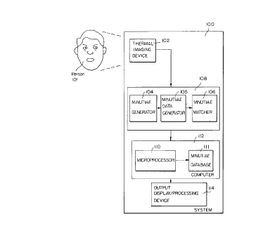
Fig. I is a block diagram of a system for recognizing faces
according to the present invention;
Figs. 2a and 2b are front and side views respectively? of the
10vascular system of the human head, with the location of thermal minutiae
being indicated in Fig. 2b;
5c~eh~c
Fig. 2c is a ~ view of the vascular svstem of the human brain,
Fig. 3 is a front view of the human vascular system illustrating the
location of thermal minutiae therein.
15Fig. 4 illustrates a contour plot derived from a facial thermogram
and identified facial features in accordance with the invention;
Fig. 5 illustrates a contour plot derived from a facial thermooram
and minutia points in accordance with the invention;
CA 02229630 1998-03-16
16
Fig~. 6 illustrates a =rid of cells overlaid on a contour plot derived
from a facial thermo_ram in accordance ~ ith the in~ ention:
Fj(J. 7 is facial thermogram taken from a distance of approximately
fifteen feet in accordance with the invention.
Fio. 8 is a block dia=ram of the apparatus for annotatino an image
of the human body according to the invention~
.,
Fig. 9 is a block diaoram of a modified apparatus of Fio. 8 for
identifyino reference minutiae in an annotated image;
Figs. IOa. IOb, and lOc illustrate facial minutiae superimposed on
three different thermal imaoes, respectively. of the same face:
Fig. I 1 is a block diagram of an apparatus for annotatingJ a medical
ima_e of the human bodv according to the invention:
Fio. I 2 is a thermooram of the upper chest area of an indi~ idual
taken from a distance of approximatelv fifteen feet in accordance ~~-ith the
I j invention:
Fig. I ~ illustrates the correspondin_ anatomv for the thermogram of
Fig. 12;
CA 02229630 1998-03-16
Fi~r. 1~ is a block dia(Jram representin(J apparatus for maintainino
the position of a sur(Jica] instrument relative to a sur~Jical site accordin~J to
the invention:
Fi~. 15 is a facial thermo ~ram of an alcohol-free individual:
Fi~. 16 is a facial thermo~ram of the individual of Fi~. I 5 under the
influence of alcohol.
Fj'J I7jS a (Jraph representin~J the thermal si(Jnatures of selected
minutia points of an individual prior and subsequent to use of alcohol:
Fi'J. 18 is a block dia_ram of the apparatus for detection of alcohol
and dru(J use b~, an individual accordin_ to the invention;
Fi~J. 19 is a (Jraph representin~J the results of a statistical anal~ sis of
dru~ users in a random population. and
Fi~ 20 is a block diaoram of the apparatus for detection of alcohol
and dru~ use in a random population
CA 02229630 1998-03-16
18
DETAILED DESCRIPTION
Facial Minutiae E!~traction
In Fig~ l . there is shown a svstem l 00 t'or personal identification in
accordance with the present invention S~stem 100 includes seven major
subivstems a thermal imaginQ device 102. minutiae o~enerator 104~ a minutiae data
generator 105, minutiae matcher 106, minutiae database 111~ microprocessor 110,
and output display/processin_ device 114 In a preferred embodiment. minutiae
oenerator 104~ minutiae data _~enerator 105, and minutiae matcher 106 are all
implemented by prooram instructions stored in a prog~ram memory 108~ and
10 pro~Jram memory 10'~ microprocessor 1 10. and minutiae database 1 1 1 are
implemented bv a programmed conventional computer 1 17.
In operation. thermal imaoin_ device 10~ obtains a thermal ima~ge of the
face of person 101 A di_ital signal representative of the thermal image is provided
as h1put to minutiae cgenerator 104, which Qgenerates si=nals representative of
15 thermal facial minutiae points for 101 These minutiae points have a number ofcharacteristics includino a specific location ~~ ithin the person or relative to other
min-utia, the apparent temperature at a Civen time the temperature sionature over a
period of time. whether the minutia corresponds to a vein or arterv. the width of
the blood vessel and the vector direction of branchino blood vessels from the
~0 minutia These and other characteristics are sensed and data relative thereto are
gJenerated by a minutia data oenerator 105 This data is stored in the minutiae
database 11 ] The minutiae matcher 106 compares minutiae data for known
individuals which has been stored in the database with that for unknown individuals
currently being ima_ed bv the imaging device 10~ If a match is detected. a
CA 02229630 1998-03-16
19
correspondin(~ si(~nal is sent to the output displayiprocessin~ device 11~.
In a preferred embodiment, output display/processin(~ device 114 comprises
circuitry to permit or deny access to a secured facility dependin~J on the results of
the matching performed bv minutiae matcher 106. ~n one embodiment, access is
5 perrnitted if the person lO I is recoonized as one of a oroup of authorized
personnel. In a second embodiment, access is denied if the person 101 is
recoonized as one of a oroup of unauthorized personnel. In vet another
embodiment, access is denied if the person lOI is not recoonized by system lO0.
System lO0 thus considers hidden micro parameter which lie below the sl;in
10 surface, and which cannot be easily for~ed. if at all. The lar~e number of such
micro parameters considered renders it essentially impossible to search for a person
to match another person s set of micro parameters. Furthermore. the particular
infrared band used for imagin(7 by thermal imaginlJ device 102 mav be kept secret.
or multiple bands mav be used, which further increases the difficultv involved in
con-lpromisino svstem 100. The underlvin(~ features détected by system 100 are
essentially hardwired' into the face at bir~h and remain relatively unaffected b!~
a~Jin~. thus providin(r for less inherent variabilitv than found in known reco(Jnition
sy,stems. Althouoh thermal facial minutiae have some aspects related to, and
e~tractable from. elemental shapes and mav be ta~oed to reflect the elemental
shape parameters (such as bv ta~gino with fractal dimensions), minutiae eYtraction
does not require production or consideration of elemental shapes. Furthermore,
the comparison of thermal facial minutiae is computationall!~ straightforward and
introduces sionificantly less processing overhead than the known approaches usedfor lemplate or shape comparisons.
Thermal imaoin(J device 102 mav be any device that produces a sional
representative of the thermal characteristics of the face of person l O I . In a
CA 02229630 1998-03-16
~0
preferred embodiment a conventional di~ital ~ideo camera sensitive to thermal
eneroy is used for the thermal imagin~ device 102. As described herein? it is found
that tractable imagerv for facial identification may be derived from passively
obt,~ined infrared images of facial heat emanations which can be detected by
commercially available thermal ima(~ino devices sensitive in the 3 to 12 micron
wavelens~th band. Unlih-e fingerprints that are characterized bv a limited ran~e of
intensity values corresponding to three dimensional ridgJes which are essentiallv
concentric rings about a single center, plus anomalous arches line endings, and
bifurcations, facial thermo~rams are aenerally characterized by continuously
10 var~'in~ wide distribution of temperatures includin~J multiple maxima and minima
values. Where the skin surface is unbroken there is gradual variation of
temperatures from the hot areas on either side of the nose to the relativelv cool
areas of the ears and cheeks. The eyes appear to be cooler than the rest of the
face. The nostrils and mouth, and surrounding areas~ will look v~,-arm or cool
I 5 dependin(r upon whether the subject is inha]in~J or e~chaiing throuoh them.
Discontinuities in the skin surface temperature may be evident where scars, moles,
burns. and areas of infection are found.
In some applications, thermal imaging device 102 mav be adapted for
attended operation usin~J cooperative persons 101 and a human supervisor. as with
20 identification svstems based on rolled fingerprints. In these applications the
supervisor can ensure that person l O l is properly positioned and can adjust gain
focus, and other parameter ofthermal imagin(~ de~,ice 102 to optimize the qualitv
ofthe thermal image produced by thermal imagJin~ device 102. In other
applications, thermal imaging device 102 is adapted for unattended, stand-alone
75 operation, for instance with live scans used for access control to a remote secure
facilitv. System 100 can further be configured based on an e~pectation that person
CA 02229630 1998-03-16
100 will be either cooperative (e.(J.. movin ~ to a specific requested location for
optimal ima ~in_) or uncooperative (e.g.. a mere passer-by). In environments
where uncooperative persons are e~pected. identification will be facilitated by
col]ectin_~ the maximum possible amount of data. for instance b- usin_ multiple
thermal ima(~rin J devices 102 and fast frame (i.e., samplin ~) rates. Additional
related data. referred to herein as ~'2round truth'' data. may be collected as well to
provide information on factors such as ambient temperature, absolute size of theimaged face, or the distance of the ima,~ed face from thermal imaoinC~ device 102.
Any portion of the body can be utilized for identification, but the face is
prei'erred due to its typical accessibility for ima_in_. In Fi_. 2a there is represented
the vascular system for a human face and in Fi ~. 2b there are shown minutiae
pointsl50forthefaceofFi~.2a. InFicr 3 selectedminutiaepointslS0
thrc,u2hout a human body are shown.
Since parts of the face mav be bloci~ed by (~lasses facial hair. or orientation
to thermal ima_ing device 10~. system 100 provides for identification based on
partial faces. A sufficient number of minutiae may be obtainable from portions of
the ~ace not blocked bv (~lasses, facial hair. or other concealment, to permit
mat~-hin~. Aiternatelv if fewer than a minimum number of minutiae specified for a
particular scenario are e~tracted by system 100 for a particuiar person 101 in an
unattended settin ~. that person 101 may be considered by system 100 to be
potentially dis ~uised. and output/display processino de~ice 11~ may cause an alarm
to be ~g~enerated to alert ouard personnel to that possibility.
Various perturbations, such as facial e.Ypression chanlJes, can distort the
relative locations of minutiae points. This is analo(~ous to the deformations that
occur in fin_erprints due to movement or pressure between the fin(~ers and the
prinl: surface. As described below, minutiae matcher 106 allows for some
CA 02229630 1998-03-16
variations in the position and characteristics of the minutiae~ as well as in the subset
of minutiae which are seen due to the field of view of thermal imaoin_ device 102
and. to possible obstruction of certain areas of the face in the ima_e.
As set forth in _reater detail herein, in one embodiment the minutiae
dat.abase 112 is partitioned by classifyinu data correspondino, to faces based on
minutiae-related characteristics as oenerated bv the minutiae data ~enerator 105.
In alternative embodiments, other characteristics mav be used for such
classification. Such classification is found to reduce search requirements in
connection with the operation of database 112 and minutiae matcher 106.
Minutiae Generator 104
In a preferred embodiment, minutiae oenerator 104 performs seven major
functions: desi=nation of faces axes, testin-J of face axes validity; normalization;
production of thermal contour lines. establishment of threshold radius of cur~ ature;
selection of minutiae; and assionment of characteristics to minutiae. Each of these
l j functions is described in oreater detail belo~ .
I. Desio,nation of Face ~xes
Referrin(~ now also to Fio. 4, there is shown a facial thermoo,ram 200 as
produced by thermal ima~in~ device 10~. The thermo~ram is in the form of a
contour plot derived as set forth below. In a preferred embodiment, thermooram
200 produced b~ thermal ima~in_ device 102 is represented b! di_ital si~nals, but if
an analoo, thermal ima Tino, device 102 is used, minutiae oenerator 104 can include
conventional analoo-to di_ital conversion circuitry to obtain facial thermos~ram 200
CA 02229630 1998-03-16
as a digital signal representation of the face of person 101.
Once the facial thermogram 200is produced minutiae generator 104
locates a number of facial features on thermogram 200, either with manual
assistance or automaticallv by using conventional techniques and structures as
described herein: left and ri2ht canthi 201, 202 left and right nostrils 203, 204, ancl
mouth area 205.
For clarity in illustration, only a single lcft canthus and ~1 singlc canthus arc 153~
~ shown in Fig. ~ . In a preferred embodiment, minutiae generator 104 locates the
left canthi area and the right canthi area and determines the centroid for each area.
The location ofthe centroid is essentially independent ofthe grey scale allocation
of th.e analog thermal imaoe produced by the camera 102. The centroids are
referred to as left and right canthi 201, 202 herein.
Minutiae generator 104 also determines an eve line 206 between left and
ri~ht canthi centroids 201, 202. This being done, minutiae ~generator determines a
mouth line 205 parallel to eye line 206 and passin2 through the centroid of mouth
area 205. Minutiae generator 104 next determines a vertical central line 208
perpendicular to eye line 206 and mouth area 205 and intersecting eye line 206
midvvay between left and right canthi centroids 201, 202. Minutiae oenerator 104then determines a face center point 209 on central line 208 midway between the
poinl:s of intersection of vertical central line 208 with eye line 206 and mouth 205.
Minutiae generator 104 further determines a horizontal center line 210
perpendicular to the vertical central line 208 and passing through face center point
209. Vertical central line 208 and horizontal central line 210 are designated as face
axes. Numerous other features may be used to define face axes but in general it is
preferable to define face axes based on areas of the face that are not greatly
~ deformable.
CA 02229630 1998-03-16
.
2~
Other techniques may be used for location of the face center point 209 in
those cases where the preferred use of facial svmmetry and recoonizable thermal
features does not suffice. For example, other techniques mav be called for with
respect to facial ima(res in which an eye pa~ch is worn, eye~Jlasses are not
5 symmetrical, onlv a partial face is imaoed. the lower face is covered. or the thermal
pattern of the face is unusually distorted. The face center point 209 may in fact be
outside of the boundaries of the facial ima=e~ for instance where onlv a partialfacial imaoe is obtained due to the face beino partially blocked by another face or
some other object. If the person 101 is wearin~ glasses the pattern ofthe ~rlasses,
10 which typically block the infrared emissions from the face and thereby produce an
extended cold area with sharp thermal discontinuity. can be used to determine
approximate face a~es. Additional techniques include manual location of the facecenter point 209 and preprocessino usin~ known techniques to locate the
approximate area of the face center point 209. As described below, the face a~;es
15 may be tested for validity to determine whether the ima(re requires anv such special
treatment.
II. Testino the ~, alidity of Face Axes
Since the known techniques for identifvino left and ri~rht canthi centroids
201, 202, left and rioht nostrils 20~, 204, and mouth area 205 are subject to
20 artifacts and other sources of error, and since some ima~,es of faces are si~nificantly
asvmmetric or have features that are entirelv missin(J (e.~J., due to person 101wearin(r an eye patch or havino a disfioured face), minutiae oenerator 10~ performs
checks to help spot instances where these points mav have been incorrectl~ located
or where unusual facial imaoes are encountered. First? a check is made to ensure
CA 02229630 1998-03-16
that vertical central line 208 and mouth line 207 intersect w ithin mouth area 205
Ne.Yt, a check is made to ensure that vertical central line 20S intersects a line
connectin_~ left and ri ~ht nostrils 203.204 at point between left nostril 203 and
ri(~ht nostril 204. If either of these conditions is not met. the face is considered to
S be a special case callin_ for manual intervention to determine the best
approximation for face axes
III Normalization
In practice, it is found that preprocessinQ through normalization of ima_e
size provides advantages in later reco_nition Accordin ~Iv. minutiae C~enerator 104
uses the distances between left and ri_ht canthi centroids 201 and 202 and the
distance from face center 209 to eye line 206 to compare the size of facial
thel-mOC,ram 200 with a standard ima_e size In a preferred embodiment. Iinear
correction in the vertical and horizontal dimensions is used to normalize the size of
facial thermogram 200 to match the standard, but other normalization models
15 could be used as well,
IV Production of Thermal Contour Lines
As provided by thermal ima_in_ device 102. facial thermogram 200 consists
onl~ of an ordered list of thermal values correspondin~-~ to each small portion of the
ima~ed face Minutiae ~enerator 104 emplovs the followin(!~ procedure to produce
20 thermal contour lines for facial thermo ~ram 200:
CA 02229630 1998-03-16
'6
a. For a digitized image havin~J N bits of resolution. or ~'
bands of therma] values determine thermal contour lines havin(J a
particular current one of the ~' v alues.
b. Produce minutiae in accordance witll the steps below for the
contour lines of the current v alue.
c. Repeat a and b above. each time using new one of the ~'
values for the ' current" value. until the desired number of minutiae
have been extracted of all of the possible values have been
processed.
d. If the desired number of minutiae have not been extracted.
repeat the process be(~innin(~ ~ ith 2'-' bands of values. and reduce
the number of bands by I ~-ith each iteration. skippin g those that
are po--;ers of 2, until the desired number of minutiae have been
extracted or until no further reduction in bands can be achieved.
I ~ Various other techniques for gJeneratin 7 contour lines may also be used.
wit:h the goal being obtainingJ a sufficientl- large number of minutiae for unique
recognition, without producing too many spurious minutiae. Spurious minutiae
increase processing overhead v~-ithout benefirting reco~Jnition. The number of
thelmal bands that will produce an appropriate number of minutiae is readilv
~0 determined by trial and error for any particular application of system 100.
CA 02229630 1998-03-16
V. Establishment of ~laximum Radius of Curvature
In a preferred embodiment, points on a thermal contour are considered
minutiae if thev form inflection points for the contour. However, to avoid artifacts
resulting in too many minutiae bein~ selected, only inflection points for curvesbelow a threshold radius will be considered minutiae. Therefore, minutiae
generator 104 selects a maximum radius of curvature to be used in determining
minutiae, based on characteristics of system 100 such as the resolution of thermal
imaoin_ device 102. the lens used. the quality of the recording and processing
system, the desired number of minutiae to be extracted, the desired sensitivity and
10 vulnerability of the system to minor variations in thermal image, the accuracy of the
three dimensional model for re(Jistration of the face ima(~e, and the ma~nitude of
sy~tematic and random errors.
Vl:. Selection of ~linutiae
Since the face thermal surface can be distorted through changes in
15 expression, activities such as eatincg and talkino, tioht hats and other clothing~. sinus
inflammation, and weioht g~ain and loss. the minutiae points to be extracted must
remain fairly constant in spite of such chanoes or must be able to be filtered
throu~h those changes. Section of minutiae as described herein provide minutiae
well-suited to such factors.
Minutiae generator 104 selects minutiae from the facial thermo(~!am 200
after preprocessing as described above bv first positioning a circle of radius R on a
thermal contour such that the contour intersects the circle, crossing it at two points
and dividing it with equal area in each half ~e~t this circle is moved along the
CA 02229630 1998-03-16
2~
contour for as far as the contour can continue to intersect the circle at e.Yactly two
points while maintainin(J an equal area on either side. If. in so movin(r the contour~
a location is found where further movement would cause tlle contour to intersectthe circle at onlv one point. the contour has ended. and the end point is desi(Jnated
as minutia point. This situation tvpica]lv occurs onl~ at the edae of a facial ima(Je
anc! only rarelv within the area of the face. If a location is found where further
movement would cause the contour to intersect the circle at three or more points,
the:re is an inflection point within the circle. It can be located by considering the
slope of the contour within the circle relative to the face a~es. The point of
10 ma,~imum chancJe in slope is then designated as a minutia point. If a location is
found where further movement would cause the contour to intersect the circle at
no points. there is a small island area within the circle. The centroid ofthat island
is designated a minutia point.
Referrin(J now to Fj(J ~;, there is sho~;n a facial image on which minutia
I j points. e.g, 301. have been identified on facial thermo~;ram 200, as described
above.
VII . Assi~gnment of Characteristics to ~ linutiae
Once minutia points are selected. minutiae oenerator 104 assigns to each
such point a label containin_ (~. y, z, c~. R B T), where ~ and y are the horizontal
20 and vertical displacements of the point relative to the facial a~es, z is the thermal
valu.e of the point, ~ is the an(~le subtended b~ a tangJent to the thermal contour at
the minutia point. R is the radius as discussed above, B is the number or value of
the -thermal band in which the point is located. and T is the threshold imposed (if
anv'l as discussed herein. In some environments, not all of these characteristics will
CA 02229630 1998-03-16
'79
be used and in such situations they need not be assi_ned. Ho~ve~er, in some
applications. these characteristics may advantageously be used for matching.
It should be reco_~nized that numerous variations in the operation and
stnLcture of a minutiae ~Jenerator could be used. For instance, minutiae that are
simply centroids of areas of constant thermal values could be used. Dependin_ onthe resolution of the thermal ima_ing device 102 on the order of 300 thermal
contours mav typically be _~enerated for a face, leading to 300 minutiae. This
number of minutiae mav be sufficient for identification purposes, depending on the
application and environment in which system ] 00 is used. In some applications. it
10 may be of interest to identify faces seen in crowds or faces turned at any an ~le.
Parl:icularly in those applications, a significant number of minutiae points should be
extractable so that even a partial face can be used for identification.
As another possibility, only centroids located near the center of the face~ or
in concave areas of the face less vulnerable to artifacts due to ed~ges. could be used.
15 In other applications. minutiae may be derived using centroids of images ~~here all
thermal values less than a threshold are maintained. but those hi_her values arecollapsed into one band. Centroids may be added to the set as the threshold is
reduced. In such instance. each minutia point is characterized usin~ at least the (x,
y z. T) factors mentioned above. where T is the threshold. In a v ariation on this
~0 mimltiae ~eneration technique, inflection points produced from such thresholdin
rath, r than the centroids mav be used.
Still another variation is to use starl and stop locations from run len_th
encodin of facial thermogram 200 to provide start and stop locations for thermalcontours. Each stop/start location provides a minutia point which is characterized
'~5 by tlle (X?y,z) values discussed above.
CA 02229630 1998-03-16
~0
An additional approach is to desi(~nate undefined locations lJenerated b~
compression and subsequent eYpansion ofthe ima~e. Specifically. facial
thermo~ram ~00 is compressed using wavelet or fractal-based methods and then
eYpanded a(~ain. Because such compression techniques are lossv in a deterministic
S vva~v, a minutia set may be defined as the undefined locations resultino frorn a
cornparison of the ori(~inal ima(~e with the compressed-and-e~panded ima(~e. This
approach provides an additional advantage of compressing the data used for
recogmtlon,
The wide variety of techniques for oenerating minutiae described above
] 0 provides an added measure of security, as one attempting to mimic thermal facial
minutiae mav be able to do so if one technique for generatino minutiae is used by
minutiae generator 104~ but not if another is used. Thus without prior knowledgeof the particular technique bein~ employed by minutiae oenerator 104, system 100becomes even more difficult to comprise than it otherwise mioht have been.
As mentioned above, it may be desirable that ail thermal ima~es be scaled
to 2 standard size prior to processin_. It also may be desirable. dependin~ on the
thermal imaging system used. that all thermal imaoes first be normalized to a
standard thermal profile before processing. In alternate embodiments~ intended for
various applications and various environments these preprocessino steps may
~0 si(Jnificantly increase accurac~ in recoonition or may merely impose unnecessary
pro, essing overhead. For e~ample~ if system 100 is used in connection v. ith anoutdoor automated teller machine, thermal normalization mav be needed to deal
with seasonally wide variations in surface skin temperature.
CA 02229630 1998-03-16
Minutiae Matcher 106
As mentioned above, minutiae generator 104 and minutiae data generator
105 are used to produce minutiae data sionals for a population of known persons.The data corresponding to these signals are stored in minutiae database 1 12.
5 Thermal imaging device 102 then obtains a thermal image of an unknown person
101 and minutiae generator ] 04 produces signals representative of the minutiae
and minutiae data generator 105 generates data for the minutia for that person.
Once these signals have been produced, minutiae matcher 106 compares the signalsrepresentative of person 101 to signals from minutiae database 102 corresponding10 to minutiae data of known persons. In a preferred embodiment, minutiae matcher
106 performs three basic functions to obtain a match: alignment of the unknown
face. comparison of minutiae data, and se9~tion of a match. Each of these functions 1~~
is described in greater detail below.
I. Alignment of Unknown Face
Because there mav not be control over the position of the face of person
101 with respect to the field of view of thermal imaging device 102 when image is
obtained, the orientation of the face may not be such that the facial axes are aligned
to be horizontal and vertical. Thus, minutiae matcher 106 corrects the orientation
by rotating the image such that the facial axes are horizontal and vertical. Next,
20 com/entional processing using a three dimensional model is applied to correct for
any rotation or twist of the head. In a preferred embodiment, such processing
~ models the head as a sphere with a diameter equal to the apparent width of the
face, and anti-distorts the image to provide a view which is normal to a surface
CA 02229630 1998-03-16
plane across the forehead and upper lip and in which the center of the sphere
coincides with the face center. In a conventional manner, the nose and chin are
ignored so as not to disrupt positioning of this surface plane.
II. Comparison of Minutiae
Comparison of the minutiae data of the unknown person 101 with minutiae
data from known persons beg~ins by comparing locations of such minutiae. First,
the locations of minutiae for a known face are considered, and denoted as M(K)i.Next an allowed positional error ~ is selected. as is determined to be appropriate
for any given environment in which system 100 is used. The minutiae of the
known face are then overlaid on the minutiae of the unknown face? denoted M(U)j.Any M(U)j that are not with ~ of one of the M(K)i are ignored. Any M(K)i w hich
are not within ~ of on the M(U)j are i~nored. This leaves a residual set of minutiae
pairs. If this set is empty, there is not a match between the two imag?~es.
Othlerwise, the characteristics of the corresponding points are compared.
1~ Depending on the application, any comparison technique that considers the
characteristics (x, y, z, c., R, B, T) listed above may be used to generate a
comparison metric. In a preferred embodiment~ only the positional differences are
considered.
The simplest decision technique is to set a minimum number of pairs of
~0 corresponding minutiae for a potential match. If an unknown face and a known
face exhibit a least the minimum number of corresponding minutiae pairs~ they are
considered to be a potential match.
In an alternative embodiment, the !'\X and ~\y values for each pair of
cor-responding minutiae are determined~ and the distribution of ~y with respect to
CA 02229630 1998-03-16
~x is then determined for the overall set of minutiae pairs. The standard deviation
o:Fthat distribution is then compared against a threshold standard deviation to
determine whether a potential match exists.
In still another technique. a new error measure ~' is introduced dependent
not only on location but on thermal value (z). Minutiae pairs are only considered if
they are within a certain thermal value difference '\z as well as have locations~ithin the distance error ~, thereby satisfying new error measure ~'.
Further levels of decision requirements can similarly be added to produce
the desired level of confidence in the match for the application at hand. Each
10 possible comparison of the unknown face with known faces is performed~ and then
the known images are rank-ordered according to the goodness of fit (e.g, closeness
in metric) with the unknown face.
III. Selection of a Match
Through experience with use of the s~stem on new images of known
15 persons, a threshold value is established to provide a desired ratio of false positive
and false negative identifications appropriate to the particular application. In a
preferred embodiment both self-correlations of multiple images of known persons
and cross-correlations of different known persons in the database are used to help
establish this threshold.
If onlv one known person meets the threshold requirement, that person is
selected as the match. If no known person meet the threshold requirement, a
failure to match signal is produced. If multiple known persons match the unknownperson to within the threshold difference, the best matching person is se!ected.Alternatively, if multiple images of the same known person are referenced in
CA 02229630 1998-03-16
34
minutiae database 112. the person having the highest ratio of matches u ithin the
top :number of best matches may be used. For instance if there are ten images ofeacl~ I;nown person in database 112, the top ten matching images determined by
mimltiae comparison are considered. The person who is associated with the most
of the top ten is selected to be the matching person. Additional levels of decision
requirements may be added. either in a simple manner or iteratively, uith a
determination after each level as to whether a match decision can yet be made.
In an alternative embodiment, minutiae matching is performed using
tech:niques disclosed in U.S. patent application No. 07/984,514, filed December 2,
1992, and U.S. patent No. 0~/314,729, filed September 29, 1994. which is a
continuation of U. S. patent application No. 07/9S4,514 both of which are herebyincorporated by reference in this application as if the entire contents of each had
been fully reproduced herein In this alternative embodiment, flash correlation is
used to match minutiae through a digitized artifact-producing technique. In this15 embodiment, the size of a minutia point is preferably increased to represent the
possible error in its location, and minuti~e are replicated successively along the face
axes to increase their density and thereby increase the discernability of the
correlation artifact that indicates a match between tu o images being compared.
Such artifact is found to occur if any only if there is a match between two pixelized
20 images.
Other known matching techniques may alternatively be used in minutiae
matc:her 106, with tolerances established for errors due to imperfect knov~ ledge of
head position or distance, errors introduced by considering the head or face as a
two dimensional surface or as a sphere, and other systematic and random residual25 errors. Some known fingerprint matching techniques may also be adapted to usewith minutiae matcher 106. By analooizin_ themlal contour to fingerprint ridges,
CA 02229630 1998-03-16
the multiplicity of facial thermal contours may be treated in a manner similar to
ma:ching many fingers per person. Alternativelv, specific areas of the face such as
surrounding the canthi. may be selected and used alone for identification
Depending on the resolution of the thermal imaging device ] 0~, several hundred
5 minutiae may be extracted from a facial thermal image. As noted above, lack ofprior knowledge of which facial features, and which specific matching techniquesare used for any particular application by svstem 100 increases the security of
system 100 against being compromised by third parties.
~ For applications of svstem 100 to environments where legal proof of
10 identification is important. a classification scheme for faces may be useful. as
fingerprints traditionallv have been classified into various classes for such
applications. For e~;ample. whorls, arches, and loops are conventional descriptors
applied to ridges in the center of a finger.
Another approach to classification of facial thermograms relates to obvious
15 characteristics for use in verbally descrihino a given facial thermogram. Such
characteristics include whether the canthi are merged or separated; whether the
thermal contour of the nose is relatively cold, hot, or normal; whether the nose is
trapezoidal in shape or irregular in shape; the degree of thermal svmmetr of theforehead; and the degree of symmetry in location of thermal features in the mouth
~0 corners, the inner curves of the cheeks, the nose, the canthi, and the outer corners
of the eyes. To be useful, such designations should remain consistent over
variations in imaging equipment, environmental conditions, physiological variables,
and other sources of errors. .~ccordingly, classification should not rely on features
determined to be highly sensitive to such factors. Classifications based on overall
~ ~ image, e.g., those based on some ofthe distances between the features discussed in
connection with Fig. 4 may be suitable for use.
CA 02229630 1998-03-16
36
Another approach is to use wavelet coefficients that produce the minimum
difference between an interpolated wavelet-compressed image and the original
irna(Je. Depending on how many classes are desired~ that number of wavelet
ccefficient sets can be generated. Each image to be classified is compressed andthen restored using each of the sets. The image is assigned to the class
correspondino to the set of uavelet coefficients which best restores the image to its
original form.
Referring now to Fig. 6, classification of faces is achievable based on the
nurnber of minutiae, their characteristics, and their distribution over the face. A
10 preferred classification method segments the face represented by thermouram 200
into a grid 401 of cells 402. Each cell is then classified based on the number of
minutiae located therein. As an example, the facial thermogram 200 of Fig. 6 is
divided into a grid 401. the cells 40'2 of which might be characterized as type A if
the cell contains less than 3 minutiae, type B if the cell contains between 3 and 5
15 minutiae. and tvpe C if the grid contains more than 5 minutiae. A face can then be
cla.ssified based on the number of cells of each type that are found. For instance,
one classification scheme is based on the number oftype A and type C cells. If aface is divided in to 36 grid cells as illustrated in Fig. 6 classes could be desigrnated
as nAmC, where n is the number of type A cells m is the number of type C cells,
20 n+m = 36 - p, and p is the number of B cells. Using this arrangement, 1260
classifications are possible. Alternatively, ranges of values can be considered to be
wil:hin the same class.
As a further refinement to such classification, the degree of bilateral
syrnmetry in distribution of type A cells and type C cells could be considered. If
25 the face is divided into four quadrants designated upper rioht, lower right, upper
left, lower left, each quadrant having 9 cells, a metric for classification could lool;
CA 02229630 1998-03-16
at differences in the numbers of h~pe A and type C cells in horizontally or v ertically
adjacent quadrants. Such metrics may be the absolute difference in minutiae
between such quadrant pairs or may be simplified by merely indicating ~ hether alef't (or upper) quadrant has more, fewer, or equal minutiae as a corresponding
5 right (or lower) quadrant.
Other possible classifications are based on geometric values of, and ratios
among, the points and lines described in connection with Fig. 4, once the face has
been normalized as described above. In some applications. a combination of visual
and thermal attributes may be employed for classification. For example, a ratio
bel:ween the distance between left and right canthi centroids 201, 202 in facialthermogram and the distance between the left and right pupils as determined
through visual imaging is found to be a useful metric for classification, as is the
ratio between the distance from eye line 206 to horizontal central line 210 and the
distance from a line connecting the eyes to the tip of the nose as determined by15 visual imaging, as is the ratio between the distance between left and right nostrils
20:3, 204 and the distance between the outer limits of the nostrils as determined by
visual imaging.
The usefulness of facial thermal imaging in recognition applications is
increased by appropriately encoding thermal facial ima_es so that consistent codes
20 are generated each time a facial thermogram of a person is obtained. Such a
coding scheme reduces database search and minutiae matching overhead, thereby
allowing faster processing using less expensive equipment. In a preferred
embodiment, overlayin~ a grid on a face such that 144 cells cover the area of the
face, and assigning a binary code to each cell, such t hat the cell is encoded with a
25 ~1" if the cell contains one or more minutiae and 0" if the cell does not contain
any minutiae, is found in practice to yield _ood results. Since this encodin~J scheme
CA 02229630 1998-03-16
preserves the relative location of each bit, it is strai~htforward to ignore selected
bil:s in cases where oniy a portion of a face is imaoed due to obstruction. disguise,
or orientation.
Use of such a -facecode'' also facilitates straightforward verification and
5 comparison techniques. In some verification applications, for example~ a
requirement that 10% ofthe coded bits match may be considered sufficient to
pn~vide a desired level of confidence. Simple difference comparison on a bit-by-bit
basis, which is computationally extremely efficient, is sufficient to determine the
number of correspondin(J bits between a code of an unknown face and that of a
10 known face. U~here multiple known faces exceed a threshold level of similarity, the
one with the greater number of common bits is readily selected as a best match.
AlthoucJh the discussion above has been directed to thermal images of
faces, it should be recognized that similar techniques and systems may readily be
applied to images of other body parts in accordance ~ith the present invention. It
15 should also be recoonized that numerous other imagin(r modalities besides thermal
imaging may be employed in accordance with the present invention, for example
x-ray, NMR, MRI, and CAT scan imaginCJ. It should also be recognized that
known schemes for pattern recoonition and (~raph matching may be applied readilyin accordance with the present invention, depending on the needs of a particular
~0 application.
Standardized Infrared Minutiae Co-ordinate Svstem (SIMCOS)
The method and apparatus described above for facial minutiae extraction
can be used to develop a standardized minutiae co-ordinate svstem for
identification of medical patients and for diagnosis of medical conditions. Because
CA 02229630 1998-03-16
an infrared camera operates at a distance from the patient and detects and records
only radiant heat spontaneously emitted from the body surface, it constitutes a
painless, non-invasive. passive method of recordinc~ patterns of bodv surface
temperatures. These patterns have been found to depend upon the underlying
S vascular structure and are unique for each person. Infrared identification therefore
provides a method for uniquely identifying individuals under all lighting conditions,
in,-luding total darkness. It is not prone to forgery or multiple identity deception
and so provides convenient and highly secure identification of individuals. The
ml. thod for generating repeatable registration points on the skin surface of the
10 hu.man body utilizes discrete minutiae points obtained from the thermal imag~es.
Visual characteristics of the body, such as size and shape and relative position of
bcdy parts, are maintained in the infrared image. In addition, the details of the
vascular s~stem are indicated by the distribution of temperature across the skinsurface. Current infrared cameras are sufficiently sensitive to temperature
15 variations that they clearly distinguish the skin directly overlaying blood vessels due
to the thermal difference caused by the flow of ~-arm blood. The vascular
structure appears as a white (hot) overlay of the circulatory structure on top of a
grey scale image of the thermal map of the body. as shown in Fig. 7.
In Fig. 8, there is shown apparatus I OOa for processing infrared images to
20 yield repeatable minutiae points correspondin_ to specific vascular locations under
the skin. The apparatus includes a thermal imaging device 102 for pr'oducing a
thermal image I. A minutiae _enerator 104 and minutia data ,enerator 105 are part
of the program memory 108 as is a minutiae overlay device 1 16. The set of
minutiae obtained from any extended area ofthe body is unique to each individual.
25 In particular, facial minutiae are unique between identical t~ins. The same thermal
minutiae are repeatedly e~tracted from a g~iven individual. They are overlaid by the
CA 02229630 1998-03-16
overlay device ] 16 and annotated by an image processor 1 ~ 8 on the infrared image
or on a visual or any image obtained from another medical sensor having the sameorientation to the subject. From the processor, the annotated image signal is
de,livered to an output display/processing device wl1ich produces the thermal image
5 with overlay IO.
In Fig. 9, there is shown a modified apparatus 1 OOb to that of Fig. ~
wherein a reference minutiae identifier 120 is provided between the minutiae data
generator 105 and the minutiae overlay device 116 to identify and specif reference
points 151 in the thermal image and overlay IO. The reference points allow manual
10 or automated comparison, merging, or registration among a set of images talien at
different times with different orientations or different medical instruments. Figs.
l Oa-c illustrate minutiae automatically extracted from a facial thermogram as the
head turns. Current infrared cameras commonly produce 30 frames of video
ou~ put per second and minutiae extraction and annotation can be performed in real
15 tin-le as those frames are generated.
Fig. I l illustrates alternate apparatus l OOc for generating a medical image
MI of a portion of the body via a medical imaging device 177 such as an x-ray
machine. The medical image can be annotated with a minutiae overlay to generate
a medical image with minutiae overlay MIO from the output displavlprocessing
~0 device.
The inventive technique differs from visible recognition approaches in that
it d.oes not merely sample a finite number of points on an image; it extracts points
which have particular meaning. This provides increased resolution at the same
time it reduces the degree of computation required. The essential features of the
75 technique are the uniqueness and invariance of thermograms~ the use of a passive
imaging technique to obtain subsurface details, the use of automated minutiae
CA 02229630 1998-03-16
4]
e~;traction to match different images taken of the same individual. and the use of
standardized minutiae locations to compare different persons or the same person as
he grows from childhood to adulthood. The matching technique involves
developing sets of corresponding points in two images. morphing one image into
5 the reference, and measuring the degree of morphing as an indicator of the amount
of difference. Similar automated procedures are then used to verity that imager~ is
from the same patient, identify a patient by comparison to a database of images,and compare images taken at different time and/or with different sensor modalities.
The minutiae extraction and annotation procedure locates the position of
10 eac:h minutia. In addition, it may note characteristics of each point such as a vector
indicating the orientation of the corresponding blood vessel, a second vector
indicating the relative orientation of the branching blood vessel, normalized
apparent temperature measure. and apparent width of the corresponding blood
vessels. As with some of the fingerprint minutiae matching machines, use of the
15 characteristic data can enhance the speed and accuracy of identification.
Fu]thermore, it can improve the accuracy and speed of automatic fusion of medical
imagery.
This basic technique can be emploved on an area-by-area basis when
poltions of the body cannot be seen or when significant changes have occurred in20 poltions of the thermogram such as when portions of the body have suffered
external wounds. This would be done by seg-menting the thermo~ram to consider
only the portions of the body in which the minutiae can be detected. Functionally.
this is equivalent to matching a latent partial fingerprint found at a crime scene to a
full rolled print filed in the FBI system. The set of minutiae points, together with
25 characteristics which describe each such point and its relation to other minutiae is
considered unique to the individual and persistent. for both contact fingerprints and
CA 02229630 1998-03-16
4~
thermal minutiae.
Verification that tw.o medical images are from the same person can be an
end goal in itself or the first step in further processin_ the two ima_es to extract
co-mparison data. Telemedicine applications, electronic filing systems~ insurance
5 claims processing, updating of medical records, and extraction of medical histories
during emergency treatment are some of the situations in which it is essential to
have a reliable, fool-proof method for positive identification of the subject and
precise localization of ima_ed areas.
The use of infrared identification (IRlD) has several advantages over other
10 methods for recognition of persons. IRID operates reg~ardless of liyhting
conditions. It requires onlv a single frame of ima_erv. taken in 1/30 of a second,
for positive identification. and so can provide on-the-flv recognition during
emergency admissions or evacuations. The imagery can be collected at a distance,~A~ithout causin_ a delav or inconvenience to the subject. No parts of the system
I i come into contact with the subject. Since thermal images are essentially immune
from variations caused bv illumination and shadows, it is not necessary to control
those variables. IRID provides continuous identification and confirmation
ve1ification of ID even in the dark. A cheaper, cruder form of thermal imaging can
be obtained from use of heat-sensitive crystal sheets which require contact with20 the skin. More expensive, active imag~ing of the v ascular system can be obtained
from laser doppler. Either of these could be the source imager for extraction ofminutiae; however, the operational advantages of passive thermal imacgers make
them the preferred sensor.
Thermal minutiae can be obtained from commercially-available thermal
2i imaging devices sensitive in the 3 to 5 or ~ to 12 micron wavelength bands.
Images are this type are shown in Figs. 7. 10, 12. and 13.
CA 02229630 1998-03-16
Current infrared cameras produce a standard analoa or digJital output
providing 30 frames per minute as shown in Figrs. 7-10. Tracking the minutiae
from frame to frame assists in the exploitation of the dynamic IR imagery by
allowing measurements to be made over time from the same body locations while
5 accommodating changes in position due to respiration, voluntary or involuntarymovements of the subject, and intentional or accidental variation in the position of
thl im~ginC~ system. The use of infrared video imagery also allo~A~s the imagery to
be recorded in real time for later analysis, and provides a self-documenting chain of
custody identification of the person recorded, all u ithout the necessity for the
] 0 cooperation of the person being imaged.
Infrared imaging can be used to locate minutiae points over the entire body
surface which correspond to intersection points and branch points of the
underlaying blood vessels. This provides a built-in set of registration points on the
body's surface, which can be annotated onto imaaes produced by any medical
15 sensor used in conjunction with the thermal imager. The registration points then
ca-n be used to compare and combine medical images taken with different
equipment at different times and under different conditions facilitating comparison
of those images. Also the minutiae points provide reference points for continuous
re-alignment of surgical instruments, radiation sources, and other diagnostic or20 treatment equipment. Since the infrared camera is totally passive, it can be used
continuously during other medical procedures to overlay precise re(ristration points
on the other images while also monitoring for overheating, shock hypothermia,
renal failure, and other medical conditions. At the same time, the pattern of
minutiae points superimposed on each image provides positive identification of the
25 patient. Such applications are of particular importance during telemedicine
procedures.
CA 02229630 1998-03-16
44
The normal body is basically thermally bilaterallv symmetric. Side to side
variations are typically less than 0.~5 degrees Celsius. This fact is used in assigning
axes to the body's image. \A'here the sl;in surface is unbrol~en there is (~radual
v ariation of temperatures across blood vessels, ~~ith the highest temperatures
5 across the body surface being directly on top of major b]ood vessels. Major
thermal discontinuities occur at entrances to body cavities such as the eye sockets~
nostrils, or moth. These provide ~lobal reference points for automatic orientation
of the thermal image. Local and relatively minor discontinuities in the sl~in surface
occur at scars~ moles, burns, and areas of infection. The thermal surface can be10 distorted throu_h pressures and activities such as eatin=,~ exercising, wearin~ tight
hats and other clothing sinus inflammation, infection~ wei(rht gain and ]oss, and
body position. However, the minutiae points remain constant with respect to their
position relative to the underlying blood vessels.
The technique for thermal minutiae extraction and matching can be
15 summarized as follows:
1. Current thermal image is digitized.
~. Current image is divided into pixels, ~~here the size of the
pixel relates to the resolution or quality of the result desired.
3. Certain pixels are selected as minutiae points.
'~0 4. Each minutia is assigned a vector havin, magnitude and
directional information in relation to the surrounding characteristics
of the thermal image. Additional characteristics, such as type of
CA 02229630 1998-03-16
4~
minutia may also be recorded for each. Typically for each u;hole
body thermal image, there uould be on the order of 1200 minutiae.
5. Set of minutiae vectors of the current image are compared
by computer to the set of vectors of other images.
6. Comparison results are used to determine corresponding
minutiae from the two images, and to morph or mathematically
adjust one image with respect to the other to facilitate comparison.
7. Differences between the current imag,e and database images
are computed for either the entire image or for areas of interest.
It is desirable that all thermal images in a database be normalized to a
st;lndard thermal range and be scaled to a standard size during search and
comparison procedures. Both normalization and scaling eliminate some minute
arnount of identifying characteristics of a particular person or his condition.
However, the standardization procedures greatly aid in the exploitation of the
database by reducing the need to calibrate every imaging sensor used to produce
images which will be filed in, or compared to database images. For example, in
ac:cident triage with no accurate ground truth reference in the scene ànd possibly
use of inferior qualitv imagers, standardization to constant size and thermal range is
appropriate in order to match against database. Furthermore, standardization
facilitates use of simulated imagery for telemedicine and telesurgery applications.
For example, when incorporated into the military's automated battlefield medicalpod, real time normalized thermal minutiae can be used to properly position
CA 02229630 1998-03-16
46
injections and application of external pressure to stop bleeding
In addition. standardizing~ database imag~es facilitates comparison of
imagery during c~ro-~th from childhood to adulthood, compilation of medical
libraries of images from ]aro~e number of people~ and automated comparisons of
current ima_er T against the vast libraries for diagnostic purposes. Standardization
to a common use of thermal minutiae would also provide a common reference for
comparing images obtained from different sensors which produce different
resolution ima_es.
There is _reat utility to maintaining a summary medical record which could
10 be carried in encrypted form on a small token or card. It would include important
medical history information, and would provide linkage into database holding more
complete information. The use of thermal minutiae can be of assistance, since itprovide a standardized technique for segmenting the complete body~ using the
thermal minutiae as nodes on a grid of finite elements.. The resultin_ cells in the
1~ gr.id would be coded based upon the compilation of all medical historv data relating
to that area of the body, and compared against the standardized imagery and status
of the correspondin-~ cell in reference model. If there were no entrv throughoutthe medical record for any imagery, diagnostics~ treatment. or injury involving that
area of the body, or no sig~nificant deviation from the reference model, there would
20 be no data for the cell. If a known standard condition involving that area were
known, then the standard code for that condition would be entered. Other codes
would pertain to unknown conditions, continuing treatment, previous conditions
su cessfully treated, etc. Conditions which are not localized, such as high blood
pressure, wou]d by convention be assigned to specific cells within the body outline.
~ 2~ The identification techniques set forth herein can be used to diagnose and
monitor treatment for burn victims, for stroke diagnosis, and in telesur_erv and
CA 02229630 1998-03-16
telemedicine.
Blood vessels that car~ nutrients to the skin are destroyed ~vhen tissue is
burned. A high pouered laser can be used to remove the burned skin, leaving, thehealthy sl;in intact. Laser li_ht is differentially absorbed and reflected by live and
dead skin, such as in the area of a burn. Certain dyes such as indocyanine fluoresce
when in contact with laser light and can be injected into a patient s blood to
indicate healthy tissue. Alternately, an IR imager can be used to indicate dead skin
vs. health~ skin, since the dead skin appears relatively cold as a result of having no
functioning blood vessels. I\lore than 100.000 person per year in the US alone
10 suf'fer severe burns. The total cost of treating these patients exceeds $2 billion.
Treatment includes massive transfusions to replace the blood lost during, sur_ery to
rernove dead skin. Blood loss is the main cause of death in burn patients.
Continued hea~,~,y bleeding often prevents a successful sl;in graft after the burned
skin is removed.
Ideally performed. laser ablation kills a 100 micrometer-thin layer of skin
belou~ the burned area. Due to the thinness, nutrients can still get through;
hou;ever. the layer stops the bleeding from preventing a good graft. IR minutiaecan be used to reposition the patient, monitor healing in specific areas, compare
valious salves dressin_s. etc. used, and re-photo_raph the person, achieving~
20 standard imag~ing results reggardless of the skin tone of the patient.
Referring now to Fig. ] 4, there is shou~n an apparatus for maintaining the
position of a surgical instrument 160 relative to a surg~ical site in a patient 162
during a surgical procedure. A thermal imaging device l 02 such as an infrared
carnera, generates a thermal image output to a minutiae generator 104 to identif~,y
2 j minutiae in the vicinity of the surgical site. As described above with reference to
Fig. 9, a reference minutia pattern is also _enerated for a statutory patient. A
CA 02229630 1998-03-16
48
sur7,ical instrument position detector 166 senses the position of the instrument and
produces an output sio~nal corresponding therewith. The minutiae pattern for thepatient and the surgical instrument positions signals are delivered to a comparator
168. The relative position ofthe instrument to the surg~ical site is set as a r.eference
5 at time 0 at 170. Displacement ofthe patient and/or the instrument with respect to
the reference at times other than O is detected by the comparator v.hich can
produce an output 17~ used to reposition the instrument via a device 174 for
proper orientation to the surgical site.
Each year, 500 00 American have strokes and 1507000 of them die, making
stroke the third leading cause of death, and the major cause of disability amo~t ~~
adults. In the near future. new drug therapies may be able to return blood flow to
stroke-damaged (ischemic) tissue protect it from permanent damag~e, and promote
recovery of function. However, the primary care physician must be able to
characterize the patient's acute neurological injury precisely enoug~h to guide
] 5 laboratory assessments and treatments. Stroke is a hetero_eneous ~roup of
conditions with many causes, levels of severity, and clinical presentations.
Identifying the point of stroke damage and the extent of damage depends
on a pattern of normal and abnormal findings. Computer tomographic (CT)
findings often are normal during the first hours after ischemic stroke. Also,
abnormalities found with neuroima_ing may be unrelated to the patient's acute
problem. Further confusing the situation, seizures, tumor, and intercranial
hernorrhage can mimic stroke. Treatment with anticoagulants or experimental
clot-dissolving agents ~ould be contraindicated in patients with hemorrha_e but
could be of value in some patients with ischemic stroke.
Continuous IR monitoring~ of the patient can possibly assist in detecting and
tracking minute variations in blood flow patterns associated with the onset
CA 02229630 1998-03-16
49
loc:ation, and severity of strol;e; and also associated with reaction to drugs and
other treatments.
Within the next 10 vears, both military and civi]ian medicine are expected to
make routine use of telesurgery where the patient and surgeon are not co-!ocated.
5 It is estimated that 90~/'o of the information a physician needs to know about a
patient can be acquired and brought to him electronically. In laparoscopic surgery
today, a surg~eon looks onl~ at video images without looking at the real organs at
all. Dermatology and pathology are both already using electronic images as v. ell as
x-ravs and medical records. Laparoscopic surgery is an electronic form of surgery.
10 Teleradiology, telepathology, and teleconsulation are already widely accepted electronic medical practices.
As telemedicine and telesurgery become more common, there will be more
potential for error in identification of patients and the treatment to be performed~
and more need to document the precise medical history and treatment procedures
15 performed by a given doctor on a given day. Filing recall, and comparison of
documentation collected over time by different sensors at different facilities ~ill
need to be automated to a reater de ree, while yrotectin_ the privacv of the
patients. The identification technique ofthe invention offers a low-cost
re~peatable, non-invasive, passive system for standardization and registration of
20 many current forms of medical imagery while also offering an approach to highsecurity maintenance of files with immediate access in emergency situations.
Identification of Drug and Alcohol Usa(~e
Many drug~s, including cocaine and alcohol, are vasoconstrictive substances
which cause cooling of the skin surface. the resultant cooling is detected through
CA 02229630 1998-03-16
passive imaging of the thermal energy emitted form the face. In Fig 15 is shown
the thermal image of an individual who is substance free and in Fig. 16 is a thermal
image of the same individual after the ingestion of alcohol.
The thermal imaging techniques of the present invention can be used to
S delect substance use by individuals, even where the individuals's identity is
unknown. This is accomplished by compiling databases of statistical analysis of
thermal signatures obtained from clinical trials in which cooperating subjects have
concurrent drug testin_ performed using urinalysis or blood testing along with
thermal signatures obtained from known subpopulation but without concurrent
testing by other means.
The vascular system supplying the human face typically exhibits thermal
variations on the order of 7~C across the facial surface. Certain general features,
suc h as hot patches in the sinus areas, relatively cool cheeks? and cold hair pertain
to all facial thermograms. Other features such as specific thermal shapes in certain
areas of the face are characteristic of a particular person Measured disturbances
to other features, such as the general symmetry between two sides of a face, range
of thermal variations in the forehead, peak temperature, size t~ canthi pattern, and
variations in those disturbances over time, may be correlated with a high
probability of drug or alcohol use.
Variations in temperature across the facial surface can be imaged by
thermal cameras sensitive to wavelengths in the 3-5? 8-12, or 2-15 micron ranges.
Current cameras can provide thermal resolution better than 0.07~C and spatial
resolution of better than .02 ", resulting in 65.000 to 265,000 discrete thermalmeasurements across the surface of the face. For most such cameras. that thermalmap is regenerated 30 times per second to produce either a standard video output~ which can then be recorded and processed on standard videotape equipment, or a
CA 02229630 1998-03-16
direct digital signal which can be immediately input to a computer.
Certain dru_s appear to produce characteristics features in facial
thermograms, which may be identifiable from detailed analysis of the structural
patl:erns and distribution statistics. Furthermore, the rate of change at any point in
5 time may be a discriminator between chronic and recent use of each drug. Usingcun-ently available thermal imaging cameras, thermal signatures emitted from theface can be used to deduce changes in activity levels of specific arteries in the brain
which are known to be affected by particular drugs.
The vascular system has a common structure in each person~ with known
10 pathways for instance from the heart to the brain, and known pathways betweenblood vessels in the face and those in the brain as shown in Figs. 2b and 2c. Using
the SIMCOS technique, a set of standardized minutiae appearing in the face can be
identified. Through clinical drug trials using known types, amounts, purity, andadministration techniques, the thermal effects over time at each such minutiae
] 5 location can be observed. The effect of varying the type~ amount, or purity
of drug can also be observed. The effect on different people can be observed.
Since the thermal effects may be quite small and localized, it is important to utilize
the SIMCOS method for identifying the precise minutiae locations in each subject.
That provides repeatability of measurements over time without requiring the
20 application of registration markers to the face, or the use of invasive techniques to
repeatably find the same locations. Also, it provides a method for comparing
corresponding locations in different subjects.
Statistical analysis of time-varying thermal signatures at each facial minutiae
point before, during and after drug or alcohol administration provides a reference
25 dataset which represents the thermal effect of that substance under the protocol
used A library of thermal minutiae substance effect signatures can be developed
CA 02229630 1998-03-16
fo:r various drugs and other substances for wvhich screening is desired, includin~ for
prescription and over the counter medications, tobacco and alcohol. Fig. 17
presents an illustration of thermal signatures associated with substance-free
subjects. These may differentiate between se~, age, size, medical history, or other
5 characteristics of the substance-free subjects. In addition, thermal minutiae on
nc,n-substance signatures ma! be developed for each person enrolled in to a system
who will be subsequently scanned for substance use. At the time that the thermaldata is collected, urinalysis or blood testing can be performed to assure that the
subject is substance-free.
Subsequently, each time a person enrolled in the system is scanned the
same facial thermal minutiae are located and the corresponding thermal signatures
computed. They are compared against that subject's own substance-free thermal
si(~,natures. If there is sufficient match, no further analysis is required. Otherwise,
the thermal si ~,natures are compared against the librar~ of substance effect
15 signatures. If there is sufficient match, the system provides an output to the system
operator that a potential substance detection has occurred.
If desired? relevant data from the svstem may be transmitted to a medical
revie~h officer for a final determination. Such data could include the current
thermal imagery of the person's face7 reference imagery from the database taken of
20 the same person when he was known to be substance-free, the thermal si~natureca.lculations which lead to the systems's determination of a possible substance
detection, the library reference thermal signature which was used by the system to
make that determination, the system's calculated confidence in the determinationthresholds which were set by the system manager relative to the infrared camera
25 sensitivity and other system factors, medical data on file about the person including
known or self-reported use of prescription or over the counter medication, or a
CA 02229630 1998-03-16
past history of substance use. The ~ledical Review Officer determines whether toaccept or override the system's determination, or specify that further testing such
as urinalysis is to be performed.
The technolo_y of this patent involves clinical studies in whicll known amounts
5 of controlled substances are administered to subjects whose thermal images aremonitored and stored to provide archival references. Analysis of those images is used
to determine the time-varying thermal effect of specific drugs at specific minutiae sites
on the face, which are specified by anatomical landmarks. After an individual ingests
a drug, changes in his or her thermal signature gradually occur until a thermal "climax"
10 is reached after which the signature gradually returns to its normal state. In chronic
drug users, permanent physiological changes may occur such that there is no lonsger
a smooth total decay of the apparent drug-induced effects. By processing a significant
number of thermal images, thermal signature markers are identified and related to
standardized vascular system locations whose thermal variation are highly correlated
15 with use of the particular substances. References may be developed for an individual,
for a class of individuals grouped by age or other characteristic, or for a general
population.
A general determination of substance-free vs. substance-influenced
classification may be based upon data collected on the thermal effects of various
20 substances of interest. In addition, certain substances produce characteristic results
which may be identifiable from detailed analysis of the thermal signatures associated
with facial minutiae, and/or with distribution statistics from those signatures.Furthermore, the rate of change at any point in time mav be a discriminator between
chronic and recent use of each drug. Techniques for processing sequences of thermal
. 25 images may enhance the visibility of bilateral asymmetries, ano.~malous static
~ conditions, and unusual time-varying trends in the thermal signatures associated with
CA 02229630 1998-03-16
.
54
specific minutiae locations in the face to indicate activity levels of specific arteries in
the brain which are knou;n to be affected by particular druos. Therefore, when asubstance is known to affect particular functions. vascular pathwavs to the
corresponding brain areas should be analyzed for related thermal signatures at
5 minutiae points along the pathways, under the assumption that increased activity at the
brain site will be found to correlate with increased v asomotor activity along pathways
leading to that site, as evidenced by thermal changes.
In order to best compare images from different people and under different
conditions, facial thermograms must be standardized and registered to common
10 coordinates The preferred approach is to use the standardized infrared minutiae
coordinate system (SIMCOS) technique which locates standard minutiae points on
each facial thermogram. In its preferred embodiment, the SIMCOS minutiae
correspond to anastomoses which are connections or branchings of major superficial
veins and arteries in the facial area. I~pproximately ] 75 such points exist in the face.
15 A subset of the SIMOS minutiae which relate to blood vessel or areas of the face
affected by a particular substances is selected. The substance activist at the brain site
will be found to correlate with increased vasomotor activity along pathwavs leading
to the site, as evidenced by thermal changes.
The collection of differences Ibetween the time-varying thermal signatures for
20 the substance-active minutiae, compared to the collection of time-varying thermal
signatures for the same points in the absence of the substance, represents the marker
for that substance. For each substance of interest, a marker may be developed for a
particular individual, for a class of persons grouped according to some criterion, or
for a more general population. The substance-free marker can likewise be developed
2~ for a particular individual class of persons, or general population.
CA 02229630 1998-03-16
In subsequent screening of a known individual for a particular substance. his
current therrnal image(s) are analyzed to extract substance-active minutiae which can
be seen in the available ima_e(s). I'he set of thermal signatures is compared to the
substance marl;er collection and substance-free marl;er collections. Measures of5 similarity are calculated for individual, class, or general population comparisons for
each substance of interest. ~arious correlation associated with substance use, or with
substance-free references in the system librarv. Normalized temperatures vs. time
waveforms for each minutiae can be compared with the corresponding waveform fromthe reference. The w aveforms are s,lid along the time axis until the best fit is found,
10 since it is not known when, if at all, the person being screened may have used that
substance. Another correlation approach involves sampling the thermal waveforms
and producing a matrix of values, where one dimension of the matrix is the number
of minutiae used, and the other is the number of temperature samples over time. The
reference library can include wider matrices, involving longer time period than is
I j practical for an operational screenino system. The comparison between the collected
matrix and the reference matrix would use a digital shifting and difference calculation
to find the best area of match.
A measure of goodness oi' match is made between the collected thermal
signatures and the si_natures for each substance under each protocol in the library.
20 The system manager selects a threshold to be applied to each comparison, such that
matches which are closer than that threshold will cause the system to issue a notice
of possible substance detection.
The results of comparison with the different markers may be recorded or
stored or output to decision marker ;. Alternativeh~, thresholds may be automatically
2j applied to the calculated differences to render a pass/fail or cleanlunder-influence
determination. The statistical estimate of confidence in the determination can also be
CA 02229630 1998-03-16
56
presented.
The apparatus for dru_ and alcohol detection is shown in Fi_. 18. Three
primary functions are performed with the apparatus: Enrollment. Reference Si_natures
Development and Screenin_. System components may in ~ eneral be rendered as
5 software, hardv.are. or firmware elements.
Prior to automated operation of the Identification and Detection (ID&D)
system, a human operator termedl a System Manager must perform set-up and
initialization of the system, which he does via the System Manager Interface, which
includes a monitor, i~eyboard, and possibly a printer and other peripherals such as a
10 mouse which are normal]y associated with personal computers. A System Mana_ermust confirrn the identity of the enrollee 4, and input the associated identification
information into the person identifier and condition identifier database 6 within the
system processor 8. The enroliee's current and past medical historv data is also input
to the system. including the results ol~urinalysis or blood tests to detect substance use,
I 5 current use of illicit substances, and other information which may bear upon alcohol
and drug testing results.
The enrollee stands or sits at designated location facing the infrared camera 12and within reach of the event trigger 14. ~'hen the event trigger is engaged by either
the enrollee or System Manager, the output from the infrared camera is sampled by
20 the frame grabber 16 and the resulting frame stored in its buffer. At the same time,
the camera output is recorded on a video cassette recorder 18 which incorporatesannotation of the date. time, location, and identifv of the enrollee.
The image in the frame grabber and buffer is processed by the face locator 20
which determines that the image includes a sing~le face which is in focus and of a
25 suitable size and position. If the image is not suitable according to software criteria
established witl1in the face locator, a new image frame is grabbed and the process
CA 02229630 1998-03-16
repeated until a suitable ima(~e is obtained.
The imaoe is then processed by the minutiae extractor and identifier 2?~11iCh
locates the SIMCOS minutiae points and extracts their positions on the image and the
corresponding apparent temperatures. Additional frames are grabbed and processed5 for a period of time selected by the system manaoer.
The extracted minutiae locations and corresponding temperatures are
processed by the thermal signature extractor 24 which generates for each minutiae
point the thermal variation over time. For enrollment purposes, a single frame may
suffice. However, multiple frames over a period of seconds should be taken in order
10 to help calibrate and factor-out noise in the system.
Personal data about the enrollee is transferred to the enrollment database 26,
along with the thermal signatures e~tracted for the enrollee. If the enrollee is l;nown
to be substance-free, the thermal si<~natures are also transferred to the substance-free
signature database 28 stored by enrollee and also to the substance-free thermal
15 signature database stored by classification of enrollee 30.
If the enrollee is known or found to be substance-influenced, the thermal
signatures are instead transferred to the substance-related thermal signature database
stored by substance and also to l:he substance-related thermal signature database
stored by protocol 34. The definiticns of protocols will relate to clinical trial used for
?0 developing reference thermal signatures? and may also include self-reporting
classifications such as heavy regular user of cocaine", or infr~quent user of
marijuana but not within the past rnonth."
The extracted thermal sionatures of the enrollee are also transferred to the
thermal signature comparator and statistical analyzer 36 which compares the
2~ signatures of the enrollee ~ith other signatures in the databases. If the enrollee's
signatures vary too much from the others in the same substance-free class or from
CA 02229630 1998-03-16
others in the same substance-related or protocol-related databases, then the svstem
manao~er may request revieu by the medical revieu officer 38 prior to including the
enrollee's data in the database.
If no anomaly is detected in the enrollee's thermal signature then the enrollee
5 is instructed as to hou- to activate the system for future access and screening. If a
personal identification number is to be used, that PIN will be assigned. If voice
recognition, ID card, or other technique for identification is to be used, thoseprocedures will be taught. The enrollee is now enrolled in the system.
~ The substance use identification and detection svstem reguires databases of
10 thermal signatures from substance-free and substance-related images. During clinical
trials in which substances are administered under ri(Jorous protocols, the same
apparatus may be used to _enerate the reference databases.
A clinical trials investigator will serve as system manager . He will perform
set-up and initialization of the system, the s~ stem mana_er interface ~ u hich includes
15 a monitor or other display~ l;eyboard and possibly a printer and other peripherals such
as a mouse which are normally associated uith personal computers The system
manager must confirm the identit:y of the enrollee 2, and input the associated
identification information into the person identifier and condition identifier database
6 within the s~stem processor 8. Since the same person may be enrolled several times
20 under various protocols~ he is termed the subject'' to emphasize that he may have
several separate files within the enrollment database ~6. The subject's current and
past medical history data is input to the svstem the first time he is imaged. During
each di~renl test involving different substances and/or protocols, the specifics of the
protocol used, as well as recent medical data including the results of urinalysis or
25 blood tests to detect substance use, will be included in the person identifier and
condition ID Buffer 6 The contents of that buffer are transmitted and stored with the
. CA 02229630 1998-03-16
results of the thermal signature extractor ~4.
The extracted thermal signatures of the subject are transferred to tlle thermal
signature comparator and statistical analyzer 36 uhich compares the signatures of the
subject with other signatures in the databases, if any. If the subject's signatures vary
5 too much from the others in the same substance-related or protocol-related databases,
then the system manager may request review by the medical revieu; officer 38 prior
to including the subject!s data in the databases.
The thermal signature comparator and statistical analyzer 36 processes the
thermal signature to establish composite signatures or common characteristics which
]O represent each ofthe databases: substance-free signatures for each person enrolled in
the system; and substance-free signatures for each designated class of enrollees, such
as: people under age 16. people 17-~0, people ~1-30, people over 30, cigarette
smokers, non-smokers, people takino, heart medication, diabetics on insulin, athletes.
vegetarians, social drinl~ers. etc. If a sufficient number of subjects is used, likewise
15 composite signatures or common characteristics will be calculated for each substance
in the database of substance-related signatures. and for each protocol.
After the end of clinical trials, frames are extracted from the archi~al
videotapes and used in place of imagi es directly talien by the infrared camera. Each
extracted frame is processed by the svstem, and the thermal signature comparator and
~0 statistical analyzer 36 selects the best matching composite signature and classifies the
frame accordingly. First, the thermal si~nature collection of that frame is classified as
better matching the composite for all substance-free trials or the composite for all
substance-related trials. Second, if the subject in the frame is judged to be substance-
free, the best matching class of database 30 is then selected. If the subject is judged
~ ~5 to be substance-related, then the besl matching substance of database 3~ is selected.
Third, in the substance-free case, the system identifies the best-matching enrolled
CA 02229630 1998-03-16
person's signatures within the class selected. In the substance-related case, the system
identifies the best- matching protocol for the substance selected. Since the true
classification of each subject on the video tape is known the performance of thesystem i~an automated mode can thus be determined, and the error rates associated
~, with the classification can be calculated. Improvements to the system can then be
made according to standard techniques for statistical analysis, including the use of
neural nets to adjust weightings consideration of the data from certain minutiae more
or less than others, normalizing the -thermal variations or not, and normalizing time
intervals based upon the size or metabolism of each subject.
When those system parameters have been adjusted to maximize the correct
classification from the video tape archives, the resulting reference signatures are
stored in database 38 and used to speed the screening of future enrollees duringoperational use of the system.
An enrolled person seeking entry through the system as an entrant stands or
1~ sits at designated location, facing the il~rared camera 12 and within reach of the event
trigger 14. When he is in position, he activates the event tri_g~er. The output from the
infrared camera is automatically sampled by the frame grabber 16 and the resulting
frame stored in its buffer. At the same time, the camera output is recorded on a video
cassette recorder 18 which incorporates annotation of the date, time, location, and
20 identity of the enrollee.
The image in the frame grabber and buffer is processed by the face location 20
which determines that the image includes a single face which is in focus and of a
suitable size and position. If the image is not suitable according to software criteria
established within the face locator"a new image frame is grabbed and the process~ 2~ repeated until a suitable image is obtained.
The image is then processed by the minutiae extractor and identifier 22 which
CA 02229630 1998-03-16
61
locates the SIMCOS minutiae points and extracts their positions on the image and the
corresponding apparent temperatures, Additional frames are grabbed and processedfor a period of time set into the system by the system manager,
The extracted minutiae locations and corresponding temperaIures are
5 processed by the thermal signature extractor ~4 w hich generates for each minutiae
point the thermal variation o~ er time.
The entrants's ID is transferred to the thermal signature comparator and
statistical analyzer 36. along with the thermal si~Snatures extracted for that entrant,
The thermal si_nature comparator and statistical analyzer compares the signatures of
10 the entrant with database of reference signatures 3 S. The closest reference signature
is selected and the entrant is designated to ha~e the same classification, That
classification is transmitted to the sy~,tem manager interface. which may grant access
through manual intervention or through automatic control of an access portal.
Depending upon the particular cla,sification selected~ or the amount of ~ariation
1 j between the entrant and the selected reference signatures, the result classification may
be sent either automatically or through manual inter~ention to a medical review officer
40 for a final determination. The entrant's file from the enrollment database ~6 is also
sent to the ~RO to provide background information.
Statistical anal~sis of drug or alcohol use ~ ithin a random population is also
~0 encompassed by the present invention, This is performed by scanning a crowd and
locating faces therein for analysis.
Various standard methods fi~r locating faces in an image frame can be used.
A particularly useful approach uses an ellipse detector to find relatively warm ellipses
(thermal faces) within a relatively cool background. The ellipse is located within the
~5 expected hei~Tht range for humans, the detected temperature is within the e~pected
range for human faces. and charact:eristics common to all facial thermograms (hot
CA 02229630 1998-03-16
canthi regions, s~mmetr~ of the e~,es nostrils, ears cheel;s, etc.) are not violated.
Each detected face in each frame.is evaluated to determine if it meets the quality
requirements for further processing. Requirements include the facial image being in
focus, being large enou_h to pro~ide adequate resolution of the facial minutiae, being
5 oriented close enough to full face forward and beino free enough of blockages
including beards eyeglasses. and intervening obstructions~ such that a sufficient
number of facial minutiae can be extracted from the facial image. The specific
requirements are dependent upon what substances are to be detected, in ho-~ small a
dose, and after what period of time. Faces w hich do not meet the qualitv requirement
10 are not further considered. Those which are qualified are assigned unique tao,s.
The next frame is then processed and qualit~ faces are detected as above.
Each such face is then compared to the faces in the previous frame, or to those fi~s 1
from the previous frame which are close enough in location that they could be a
particular face in the current frame l\,Iatching is performed using the facial minutiae
15 matching method. If a current and prior face are determined to be the same, then they
are given the same tag. This process continues with subsequent frames being likewise
analyzed. In general. a particular tagged face will move across and then out of the
field of view. U'hen the face is no longer seen by the camera, then the thermal
signatures associated ~ -ith each of its minutiae in each of the frames are combined and
20 matched against a reference datab,~se for non-substance and substance-related signatures.
The system is designed for stand-alone operation. IT is deplovable for
programmable periods of time. during which it will anal~ze and classify each face
which appears within its field of ~ie~. The svstem will not routinely record or store
25 the thermal images. although provisions are made to do that during testing and
evaluation of the system in order to allow for improvements to be made in the system
CA 02229630 1998-03-16
63
;md compnrcd with CalliCJ Ics~ s. The Ollt]lllt t~om the systeln will bc ~raphical
reslllts such as shown in Fi,g. 19. The cum~ative detection inde~; of thc y-L~isrepresents the numbcr of pcrsons whu Ihe syslern t~.ctimates have used marijuana,
cocaine, or heroin in an amoun~ l wi~hin a ~i,ner~ e. which results in ~ residual
S ~evel in~ir~tcd by thc .~;-axis value ~I Lbe lime of Ihe an~iysis. Tbe x-a~c~s represcnts
he confidence le~el of dru;, signatulc ;IId;CaUOn~ which i.~ rel~ted to the detection
l~r~rislon ofthe testing and ~nslysis procedules. Separale cur~es indicate the specific
dnl~c detected, and ~ cornpositc survcy indi~ dle~ delection of any ot'the subst~ces.
Dl-~ to the ~requent u~ of combinations of drugs~ the composite cllrve Is expected to
10 he mc~re sisnificant than its components.
The system is tested usir,lg ~;nownpop~ nls of tirug users, an~i its results
colllp~ul to ~Irinalysis results. Thc co..~l A~son is us~l lo selec~ thresholds fnr cystem
decisions on d~csific,atiorl of therm31 si~;nnturcs. ~bc s~slc~ an be deployed within
a high in~ensity ~n~g l~afIiclil~s s~e~, and its rcsults co~ red lo o~her current
1~ csuma~es of drug usa~t~. In that area.
The apparatll~ for sr~tisti~ql analysis is shown in .l~ig. 20. Three pnmary
1;-nclionc are pelfo"l,ed with the apparatus: face r~uicition and tagginB; f~ nalysis
~md ~ ;sific~rion; and stati~ti~l population analysis.
All i~dred camera 42 i~ r~ositioned such that persons in t}lc populatioa l~J b~
20 scanned ,e,cller~lly enter, uanCYe. se, and e~t the c3mer~'s ficld of ~icw 44. Thc
infral-ed ~nera produces a ~ lence of frames usin~ eilher dircct digital outpul ~lr
~;ame-~betl Yideo output 4t-, wbich is stored in the frDmc buf~er stora~,e 48.
]'roccssing of lhc imagery is inib'at~.n ~y an jniti~ r mecl ~nisrn 50 which may bc a
proximity delcc~or~ mo~ion de~ect(lr, nr other sensor used to detcct thc possiblc
prcscnce of humall~ within Ihe field of ~,iew
The system 1~ ssor 52 is compri~efl nf live components. The facc locator
CA 02229630 1998-03-16
64
54 applies rules to the buffer stored image to identify all faces in the frame. The face
quality check 22 applies additional rules to deterrnine if a given face provides sufficient
information in terms of focus, resolution, position, and number of minutiae available.
Each qualified face is tagged and then compared with qualified faces in the preceding
S frame? using the SIMCOS technique, to determine which faces have already been seen
and tagged.
Faces which are seen in a given frame, may have been temporarily blocked in
the previous frames, and so any face ~hic~ is not blocked. turned, or otherwise
unqualified part ofthe time. Comparison against earlier qualified faceslcontinued for
10 a period oftime which is considered a reasonable maximum time for transversing the
filed of view. The face tracker 54 reassigns tags so that the same face receives the
~Q~
frame tag in subsequent frames. There are two reasons to be concerned about P~
consistently applying the same tag to each face. First, drug and alcohol detection
accuracy improves when a face is analyzed for a longer period of time. Second,
15 statistical accuracy improves when each person is counted only one time, regardless
of their position or speed, or their being within a group.
Once a face has exited the i;eld of view, the thermal signature extraction
processor 60 produces time varying apparent temperature signatures for each facial
minutia seen over the course of time of all frames in which that face was seen. The
20 composite thermal signature for that face is produced at 62.
The analyzer 64 of the composite thermal signature compares each imaged
person's composite thermal signature to a database of signatures associated withknown substances and protocols or with known subpopulations such as cocaine
addicts or alcoholics. More particularly, a signature from a thermal signature database
25 from deployment 66 is compared with a signature from the reference thermal signature
68 in a comparator 70. the output of which is delivered to a thermal signature
CA 02229630 1998-03-16
classifier 72. The analyzer output is delivered to a statistical analyzer 74 forprocessing the thermal signatures by batch to produce an output summary to the
output report generator 76 for the output device 78. A statistical sufficiency analyzer
80 evaluates the report and determines whether the analysis of the population up to
that point is statistically sufficient for the intended purpose. If not~ additional frames
are analyzed. If the analysis is sufficient, then the system is re-initialized by the
initializer 50 starting a new collection of faces and leading to a new statistical
evaluation.
~f ~AD
If the population throughe~*t is well-known, the statistical analyzer 74 can be ' q
10 programmed to run for set period oftime before the batch is considered complete and
control is passed to the output repolt generator 76. Other criteria for determining a
batch size can be used. including counting the number of tags assigned or the number
of detected suspected drug users or the number of detected substance-free persons.
While in accordance with the provisions of the patent statute the preferred
] S forrns and embodiments ofthe invention have been illustrated and described, it will be
apparent to those of ordinary skill iII the art that various changes and modifications
may be made without deviating from the inventive concepts set forth above.