Language selection

Search

Patent 2229714 Summary

Third-party information liability

Some of the information on this Web page has been provided by external sources. The Government of Canada is not responsible for the accuracy, reliability or currency of the information supplied by external sources. Users wishing to rely upon this information should consult directly with the source of the information. Content provided by external sources is not subject to official languages, privacy and accessibility requirements.

Claims and Abstract availability

Any discrepancies in the text and image of the Claims and Abstract are due to differing posting times. Text of the Claims and Abstract are posted:

  • At the time the application is open to public inspection;
  • At the time of issue of the patent (grant).
(12) Patent: (11) CA 2229714
(54) English Title: INTERVERTEBRAL IMPLANT WITH COMPRESSIBLE SHAPED HOLLOW ELEMENT
(54) French Title: IMPLANT INTERVERTEBRAL AVEC CORPS CREUX PROFILE ET COMPRESSIBLE
Status: Expired
Bibliographic Data
(51) International Patent Classification (IPC):
  • A61F 2/44 (2006.01)
  • A61F 2/00 (2006.01)
  • A61F 2/28 (2006.01)
  • A61F 2/30 (2006.01)
(72) Inventors :
  • KNOTHE, INGA (Switzerland)
  • BENOIT, ALFRED (Switzerland)
(73) Owners :
  • SYNTHES USA, LLC (Not Available)
(71) Applicants :
  • SYNTHES (U.S.A.) (United States of America)
(74) Agent: MARKS & CLERK
(74) Associate agent:
(45) Issued: 2003-12-30
(86) PCT Filing Date: 1995-10-20
(87) Open to Public Inspection: 1997-05-01
Examination requested: 2000-11-22
Availability of licence: N/A
(25) Language of filing: English

Patent Cooperation Treaty (PCT): Yes
(86) PCT Filing Number: PCT/CH1995/000244
(87) International Publication Number: WO1997/015247
(85) National Entry: 1998-02-17

(30) Application Priority Data: None

Abstracts

English Abstract


The intervertebral implant consists of a flattened
shaped hollow element in the form of a hollow cylinder,
hollow truncated cone, hollow truncated pyramid or hollow
truncated wedge, with an outer surface comprising a flattened
upper bone-contact face, a flattened lower bone-contact face
and two lateral faces. The upper and lower bone-contact
faces can be compressed elastically towards the inner chamber
of the element in such a way that the maximum distance H
between the upper and lower bone-contact faces can be reduced
by 0.5 - 5.0 mm.


French Abstract

L'invention concerne un implant intervertébral constitué d'un corps creux (1) profilé aplati, se présentant sous forme de cylindre creux, de cône tronqué creux, de pyramide tronquée creuse ou de coin tronqué creux, dont la surface (2) extérieure comprend une face (3) de contact osseux supérieure et aplatie, une face (4) de contact osseux inférieure aplatie et deux faces (5) latérales. Les faces (3;4) de contact osseux supérieure et inférieure sont compressibles de façon élastique vers la cavité (6) du corps creux (1) profilé de façon à réduire la distance H maximale séparant les faces (3;4) de contact osseux supérieure et inférieure d'une valeur comprise entre 0,5 et 5,0 mm.

Claims

Note: Claims are shown in the official language in which they were submitted.


7

The embodiments of the invention in which an exclusive
property or privilege is claimed are defined as follows:

1. An intervertebral implant comprising a flattened
shaped hollow element defining an interior space within an
outer surface that includes a generally flattened upper
bone-contact face, a generally flattened lower bone-contact
face spaced by a maximum distance from the upper bone-
contact face, and includes two lateral faces, wherein the
upper and lower bone-contact faces are elastically
compressible towards the interior space of the hollow
element such that the maximum distance between the upper,
and lower bone-contact face is reducible by 0.5 to 5.0 mm
and wherein the interior space is open at anterior and
posterior ends.

2. The implant according to claim 1, wherein the lateral
faces have an arcuate shape and the maximum distance
between the upper and lower bone-contact faces is reducible
by 1-3 mm.

3. The implant according to claim 1 or 2, wherein a force
of pressure of 12 Newton on the upper and lower bone-
contact faces reduces the maximum distance by 15% to 30%.

4. The implant according to claim 1, 2 or 3, wherein the
lateral faces are provided with elongated apertures to
promote the formation of new bone.


8

5. The implant according to any one of claims 1 to 4,
wherein at least one of the bone-contact faces is textured
to stabilize the implant.

6. The implant according to claims 1 to 5, wherein at
least one of the bone-contact faces is provided with
perforations to promote bone ingrowth.

7. The implant according to any one of claims 1 to 6,
wherein at least one of the bone-contact faces is provided
with at least one central groove to facilitate compression
of the implant.

8. The implant according to any one of claims 1 to 7,
wherein the implant is made of a biocompatible plastic
material.

9. The implant according to any one of claims 1 to 8,
wherein the implant is coated with an hydroxylapatite of
tricalciumphosphate (TCP).

10. The implant according to any one of claims 1 to 9,
wherein the hollow element has the shape of a hollow
cylinder, hollow truncated cone, hollow truncated pyramid,
or hollow truncated wedge.


9

11. The implant according to any one of claims 1 to 10,
wherein both bone-contact faces are textured.

12. The implant according to any one of claims 1 to 11,
wherein both bone-contact surfaces include perforations.

13. The implant according to any one of claims 1 to 12,
wherein both bone-contact faces include a central groove to
facilitate compression of the implant.

14. The implant according to any one of claims 1 to 13,
wherein the implant is made of polyethylene.

15. An intervertebral implant comprising a flattened
shaped hollow element defining an interior space within an
outer surface that includes a generally flattened upper
bone-contact face, a generally flattened lower bone-contact
face spaced by a maximum distance from the upper bone-
contact face, two lateral faces, an engagement lip provided
within the interior space of the hollow element, and an
interlock means provided within the interior space of the
hollow element, wherein the upper and lower bone-contact
faces are elastically compressible towards the interior
space of the hollow element, such that the maximum distance
between the upper and lower bone-contact face is reducible
by 0.5 to 5.0 mm, and wherein said interlock means and
engagement lip are configured and dimensioned, such that
the engagement of the engagement lip with the interlock


10

means prevents the compression of the upper and lower bone-
contact faces.

16. An intervertebral implant comprising a hollow support
member that defines an interior space within an outer
surface that includes a generally flattened first bone-
contact face, a generally flattened second bone-contact
face, and a pair of lateral faces having an arcuate shape
and connecting the first and second bone-contact faces at a
maximum distance therebetween, wherein the support member
is made of a biocompatible material which is sufficiently
resilient to allow the first and second bone-contact faces
to be elastically compressible towards each other in the
interior space upon the application of force thereto to
reduce the maximum distance, with the bone-contact faces
attempting to return to their original configuration when
the force is removed and wherein the interior space is open
at anterior and posterior ends.

17. The implant according to claim 16, wherein at least
one of the bone-contact or lateral faces includes an
aperture to promote bone ingrowth, and at least one of the
bone-contact faces includes a texture to stabilize the
implant and at least one central groove to facilitate
compression of the implant.

18. The implant according to claim 16 or 17, wherein the
support member has the shape of a hollow cylinder, hollow


11
truncated cone, hollow truncated pyramid or hollow
truncated wedge, and is made of a plastic material so that
the maximum distance is reduced by at least 15% when the
bone-contact surfaces are compressed
19. An intervertebral implant comprising a hollow support
member that defines an interior space within an outer
surface that includes a generally flattened first bone-
contact face, a generally flattened second bone-contact
face, a pair of lateral faces having an arcuate shape and
connecting the first and second bone-contact faces at a
maximum distance therebetween, an interior wall extending
from the first bone-contact face toward the second bone-
contact face through the interior space, and interlock
means associated with the second bone-contact face for
receiving the wall, wherein the support member is made of a
biocompatible material which is sufficiently resilient to
allow the first and second bone-contact faces to be
elastically compressible towards each other in the interior
space upon the application of force thereto to reduce the
maximum distance, with the bone-contact faces attempting to
return to their original configuration when the force is
removed, and wherein engagement of the wall and the
interlock means after the bone contact faces return to
their original configuration prevents further compression
of the first and second bone-contact faces.

Description

Note: Descriptions are shown in the official language in which they were submitted.


CA 02229714 2001-07-05
1
INTERVERTEBRAL IMPLANT WITH COMPRESSIBLE SHAPED HOLLOW
ELEMENT
Intervertebral implants are used in case of fusion of
vertebral bodies, particularly in the region of the lumbar part
of the spinal column. Per intervertebral space one to two
implants are used.
From the prior art there are already different types of such
intervertebral implants known though which shave the following
disadvantages:
- to insert the implant in the intervertebral space the
respective vertebras must be expanded by means of suitable
instruments; and
- the implant is endangered of sinking in the end plates of the
respective vertebras.
Here the invention shall offer remedy. The invention is based on
the task to produce an intervertebral implant which is
insertable into the cleaned out intervertebral space in a
controllable manner without an expanding instrument.
In one aspect, the invention provides an intervertebral
implant comprising a flattened shaped hollow element
defining an interior space within an outer surface that
includes a generally flattened upper bone-contact face, a

CA 02229714 2001-07-05
2
generally flattened lower bone-contact face spaced by a
maximum distance from the upper bone-contact face, and
includes two lateral faces. The upper and lower bone-
contact faces are elastically compressible towards the
interior space of the hollow element such that the maximum
distance between the upper and lower bone-contact face is
reducible by 0.5 to 5.0 mm. The interior space is open at
anterior and posterior ends.
The flattened hollow element can have the shape of a hollow
cylinder, hollow truncated cone, hollow truncated pyramid or
hollow truncated wedge.
Dimensions, geometry and material should be chosen such, that
the maximum distance H between upper and lower bone-contact face
is seducible by 0,5 - 5,0 mm preferably 1 - 3 mm.
In case of application of a force of pressure of 12 Newton on
the upper and lower bone-contact face the maximum distance H
shall be reducible by 15 % to 30 % preferably 20 o to 25 0. The
compressibility of the implant allows its insertion without
having to apply an expanding instrument.

CA 02229714 1998-02-17
3
Therewith the advantage is reachable that a minimum expenditure
of force is necessary for the implantation and a controllable
insertion of the compressed implant is possible. A minimum
invasive and open surgery technique is therewith applicable.
The large bearing area of the implant prevents its sinking in
into the end plates.
A preferred embodiment of the invention consists therein, that
in the interior space of the hollow element an engagement lip is
provided which is engageable into an interlock means. In case of
an engaged engagement lip the compressibility of the hollow
element is neutralized again so that a usual rigid implant
results.
Bone splinters or bone replacement material can easily be filled
into the interior space of the frontally and backwardly open
hollow element and the implant securely be mounted with little
operating steps.
To advance a quick ingrowing of the bone the implant is suitably
provided with perforations preferably in the form of
longitudinal apertures. The longitudinal apertures allow a
control of the ingrowing of the bone by means X-ray images in
case of a material which is not permeable for X-rays.

CA 02229714 1998-02-17
4
For the improvement of the stability of position of the implant
the upper and /or lower bone-contact face is provided with a
three dimensional texture preferably in the form of longitudinal
grooves.
Compared to the prior art the following further advantages of
the implant according to the invention accrue:
- security against slipping;
- improved permeability for X-rays; and
- enhanced elasticity of the implant.
The invention and further embodiments of the invention are
discussed in more detail in the following by means of the
partially schematic representations of an embodiment of the
invention.
The figures show:
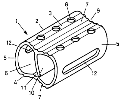
Fig. 1 a perspectival representation of the implant
according to the invention in the compressible state with a
loose engagement lip: and
Fig. 2 a cross-section through the implant according to
fig. 1 in the non-compressible state with engaged
engagement lip.

CA 02229714 1998-02-17
The intervertebral implant shown in fig. 1 and 2 consists
essentially of a hollow element 1 in the shape of a hollow
cylinder whose outer surface 2 consists of a flattened upper
bone-contact face 3, a flattened lower bone-contact face 4 and
two lateral faces 5.
The implant may be fabricated in a suitable metal (i.e. Titan),
but particularly also in a synthetic material tolerated by the
body like polyethylene.
The upper and the lower bone-contact faces 3 and 4 are
elastically compressible towards the interior space 6 of the
hollow element 1, such that the maximum distance H between the
upper and the lower bone-contact face 3 and 4 is reducable,
typically by 2 mm. This renders possible an easy insertion of
the implant into the intervertebral space.
The lateral faces 5 are provided with recesses in the shape of
longitudinal holes, which may be omitted when using a synthetic
material. The upper bone-contact face 3 and/or the lower bone
contact-face 4 is provided with perforations 8 as well as with a
central groove 9.
In the interior space 6 of the hollow element 1 an engagement
lip l0 is provided, which is engageable in an interlock means
11.

CA 02229714 1998-02-17
6
In the following the clinical application is described in
detail. The hollow element 1 shown in fig. 1 is grasped at by
means of a suitable compression tool, such that a force of
pressure, typically 12 Newton, may be applied on the upper and
the lower bone-contact faces 3 and 4 which compresses the hollow
element 1. In this state the implant is inserted into the
emptied intervertebral space as ever possible without
distraction tools whereby the three dimensional textures 7 in
the shape of longitudinal grooves facilitate the leading of the
implant and offer a protection against a possible slipping.
The compression tool is removed and the engagement lip 10 is set
upright and engaged into the interlock means 11 such that the
hollow element 1 is not compressible any longer. The implant may
now be filled with bone splinters or bone replacement material.

Representative Drawing
A single figure which represents the drawing illustrating the invention.
Administrative Status

For a clearer understanding of the status of the application/patent presented on this page, the site Disclaimer , as well as the definitions for Patent , Administrative Status , Maintenance Fee  and Payment History  should be consulted.

Administrative Status

Title Date
Forecasted Issue Date 2003-12-30
(86) PCT Filing Date 1995-10-20
(87) PCT Publication Date 1997-05-01
(85) National Entry 1998-02-17
Examination Requested 2000-11-22
(45) Issued 2003-12-30
Expired 2015-10-20

Abandonment History

There is no abandonment history.

Payment History

Fee Type Anniversary Year Due Date Amount Paid Paid Date
Registration of a document - section 124 $100.00 1998-02-17
Application Fee $300.00 1998-02-17
Maintenance Fee - Application - New Act 2 1997-10-20 $100.00 1998-02-17
Maintenance Fee - Application - New Act 3 1998-10-20 $100.00 1998-09-08
Maintenance Fee - Application - New Act 4 1999-10-20 $100.00 1999-08-18
Maintenance Fee - Application - New Act 5 2000-10-20 $150.00 2000-07-26
Request for Examination $400.00 2000-11-22
Maintenance Fee - Application - New Act 6 2001-10-22 $150.00 2001-10-01
Maintenance Fee - Application - New Act 7 2002-10-21 $150.00 2002-10-21
Final Fee $300.00 2003-10-06
Maintenance Fee - Application - New Act 8 2003-10-20 $150.00 2003-10-15
Maintenance Fee - Patent - New Act 9 2004-10-20 $200.00 2004-10-07
Maintenance Fee - Patent - New Act 10 2005-10-20 $250.00 2005-09-26
Maintenance Fee - Patent - New Act 11 2006-10-20 $250.00 2006-10-03
Maintenance Fee - Patent - New Act 12 2007-10-22 $250.00 2007-10-03
Maintenance Fee - Patent - New Act 13 2008-10-20 $250.00 2008-09-15
Registration of a document - section 124 $100.00 2009-03-13
Maintenance Fee - Patent - New Act 14 2009-10-20 $250.00 2009-09-14
Maintenance Fee - Patent - New Act 15 2010-10-20 $450.00 2010-09-16
Maintenance Fee - Patent - New Act 16 2011-10-20 $450.00 2011-09-20
Maintenance Fee - Patent - New Act 17 2012-10-22 $450.00 2012-09-12
Maintenance Fee - Patent - New Act 18 2013-10-21 $450.00 2013-09-13
Maintenance Fee - Patent - New Act 19 2014-10-20 $450.00 2014-09-24
Owners on Record

Note: Records showing the ownership history in alphabetical order.

Current Owners on Record
SYNTHES USA, LLC
Past Owners on Record
BENOIT, ALFRED
KNOTHE, INGA
SYNTHES (U.S.A.)
Past Owners that do not appear in the "Owners on Record" listing will appear in other documentation within the application.
Documents

To view selected files, please enter reCAPTCHA code :


To view images, click a link in the Document Description column. To download the documents, select one or more checkboxes in the first column and then click the "Download Selected in PDF format (Zip Archive)" or the "Download Selected as Single PDF" button.

List of published and non-published patent-specific documents on the CPD .

If you have any difficulty accessing content, you can call the Client Service Centre at 1-866-997-1936 or send them an e-mail at CIPO Client Service Centre.


Document
Description 
Date
(yyyy-mm-dd) 
Number of pages   Size of Image (KB) 
Description 1998-02-17 6 158
Claims 1998-02-17 3 60
Drawings 1998-02-17 1 14
Cover Page 1998-05-26 1 44
Representative Drawing 1998-05-26 1 7
Representative Drawing 2003-11-27 1 10
Abstract 2003-11-27 1 16
Cover Page 2003-12-09 1 39
Abstract 1998-02-17 1 16
Description 2001-07-05 6 174
Claims 2001-07-05 5 193
Assignment 1998-02-17 3 202
PCT 1998-02-17 13 448
PCT 1998-04-29 7 203
Prosecution-Amendment 2000-11-22 1 26
Prosecution-Amendment 2001-07-05 9 304
Prosecution-Amendment 2001-07-25 1 21
Correspondence 2003-10-06 1 33
Assignment 2009-03-13 11 620