Note: Descriptions are shown in the official language in which they were submitted.
CA 02229808 1998-02-17
, ... ...
WO 97/08034 PCT/EP96/03703
Profiles for sheetlike composite elements
The present invention relates to new profiles
for use as reinforcement or bordering of sheetlike
composite elements ("sandwich elements"), to the compo-
site elements constructed with these profiles, and to a
process for producing these composite elements.
Sheetlike composite elements, consisting most
simply of a core layer and two top layers connected by
this core layer and surface-bonded to it, the material
employed for the core layer generally being a rigid foam
and the material employed for the top layers generally
being sheet metal or another material having tensile
strength, are increasingly used as a construction
material owing to their low weight and advantageous
mechanical properties. In transportation in particular,
i.e. in the construction of commercial vehicles of all
kinds, for example lorries, buses or rail vehicles, or
of freight containers, they are employed in particular
for floor, wall and ceiling constructions.
Here and in the text below the term "sheetlike" compo-
site elements does not refer exclusively to $1at compo-
nents but also to curved part~, such as the roofs of
rail carriages, whose form can essentially be described
by cylindrical areas or by a combination of flat and
cylindrical area~.
Owing to the limited stability of these composite
elements in the case o~ locally concentrated stresses,
especially as a result of $orces acting in a punctiform
or linear manner perpendicularly to the layers and above
all in the border region, it is frequently necessary to
install reinforcing elements at the appropriate points,
i.e. places where fixing elements need to be attached to
CA 02229808 1998-02-17
.. , ~,~
join the composite elements to one another, to other
load-bearing structural components or to mechanically
stressed fitments (e.g. seats, holding rails or luggage
racks in public transport vehicles), these reinforcing
elements being in the ~orm of profiles of metal or
another high-strength material.
The term border profiles is used here and below to
denote those profiles which form the border o~ a
composite element or which join two composite elements
to one another at their borders (joining profiles).
Insert profiles denote those pro~iles which ~or
reinforcement purposes are arranged in the interior of
the composite element, the core layer being interrupted
at the appro-priate point and the top layers rllnn;ng on
over the profile.
Both the core layer and the top layers can be
homogeneous or can be constructed in turn from a
plurality of layers. For example, a reinforcing layer
can be embedded in a core layer o~ ~oam, or a top layer
may, ~or example, consist o~ plywood.
The composite elements are normally produced by coating
one or both sides of the top layers (consisting for
example of sheet aluminium), the core material and the
insert or border profiles - having simple cross-
sections, in general, usual square profiles - with an
adhesive, initially on the boundary ~aces. Subse~uently,
the individual parts are brought together in the desired
geometric arrangement in a bon~; ng mould and surface-
bonded by external pressure. The external pressure
employed is ~re~uently the atmospheric air pressure, the
bo~;ng mould being covered with an airtight ~ilm and
evacuated. In order to obtain a good bond and a flawless
surface, it is necessary to allow the air between the
CA 02229808 1998-02-17
layers, and also any excess adhesive, to escape as fully
as possible. To this end the core layer is often
provided with a relatively large number of parallel
slots or grooves through which the air is able to pass
to the border of the composite element. When using
customary commercial profiles, for example in U, Z or H
cross-section, however, this is no longer ensured.
Indeed, in order to achieve high mechanical stability
these profiles must be bonded over their entire area
both to the top layers and to the narrow side of the
core layer, leaving no room in between for the escape of
air. Consequently, the production of composite elements
of large surface area in particular is often
accompanied, especially in the region of the pro~iles,
by the formation of air bubbles, which may considerably
impair the mechanical properties and may also be visible
on the exterior of the component.
The ob~ect of the present invention, therefore,
was to provide new profiles which do not give rise to
these disadvantageous phenomena in the production o~
sheetlike composite elements.
This ob~ect is achieved in accordance with the
invention by the profiles according to Patent Claim 1.
In their simplest form, the profiles consist of two
essentially parallel arms whose inside or outside serves
as a bearing surface for in each case one of the top
layers, of a connecting crosspiece between the arms, and
of a bearing surface for the narrow side of the core
layer. The geometric spacing of the arms, i.e. the
distance between the planes defined by the bearing
sur~aces for the top layers, corresponds to the distance
between the top layers of the composite elements that
are to be produced with the profile; the bearing surface
CA 02229808 1998-02-17
. .~ ":
-- 4
for the core layer lies between these planeg. Depen~; ng
on the relative position of the arms to one another and
to the connecting crosspiece, the profile may have an
essentially U-, Z- or H-shaped cross-section, although
transitional variants of course are also possible.
Combinations of these basic forms are also possible by
the presence of two or more connecting crosspieces
between the arms. One preferred ~orm, for example, con-
tains two opposing bearing surfaces for the core layer
and is therefore particularly suitable as an in~ert or
joining profile.
The core-layer bearing surface, which is preferably
perpendicular to the arms of the profile, is in accor-
dance with the invention not - as with a simple U, Z or
H profile - directly adjacent to these arms but instead
is separated from the connecting crosspiece by at least
one spacer which extends in the longitl-~; n~l direction
of the profile. In this arrangement, the spacer (or, in
the case of a plurality of spacers, each outer spacer)
does not adjoin an outer border of the core-layer
bearing surface but is set back from it, thus forming a
channel which extends in the longitll~; n~l direction of
the profile. The core-layer bearing surface is designed,
furthermore, so that between its outer (longitll~;n~l)
borders and the bearing sur~aces ~or the top layers, and
between the planes defined by these surfaces, there
remains in each case an interspace ext~n~; ng in the
longitll~;n~l direction of the profile. The interspaces
are preferably continuous over the entire length of the
profile but may also be interrupted at short sections as
a result, for example, of the corresponding design of
the borders. As a result of this, the bearing surface
for the core layer does not with its borders form an
CA 02229808 1998-02-17
.. , ,,:
airtight seal to the top layers in the installed state;
instead, there r~m~; n~ in each case a continuous or
interrupted gap which comm-ln;cates with at least one of
the above-described channels ext~n~;ng in the
longitl-~;n~l direction of the profile. The profile
preferably contains a corresponding channel for each
gap, it being possible for the profile also to include,
if desired, additional, open or closed channels. This
system of gaps and channels enables both air and excess
adhesive to escape without problems during the
manufacture of the composite elements. Because of the
offset of each spacer the channels have a sufficiently
large cross-section which even in long profiles allows
rapid escape o$ air and which cannot be blocked by, for
instance, the ingress of excess adhesive. Especially in
the case of vacuum bon~; ng, this achieves improved
evacuation of the interior of the component, which also
~nh~nces the strength of the adhesive surface bonds
between core layer and top layers.
The bearing surfaces for the top layers and/or
the core layer are preferably provided with slots or
grooves. When the composite elements are bonded, these
slots or grooves are able to accommodate some of the
adhesive, and possibly also material of the top layer if
the latter is readily de~ormable. This produces a
certain intermeshing effect or a positive connection,
which increases the strength of the adhesive bond. For
mechanical and manufacturing reasons, these slots or
grooves preferably extend in the longit~; n~l direction
of the profile.
In one particularly preferred design the bearing
surfaces for the top layers are on the sides of the arms
that are remote from the connecting crosspiece, i.e. on
CA 02229808 1998-02-17
... .
the outsides of the pro~ile. In the installed state they
contact the top layers o~ the composite element from
inside, the distance between the bearing surfaces corre-
spo~;ng to the thickness of the core layer. Profiles of
this design are suitable both as insert profiles in the
interior of the composite element and as border
profiles.
In another preferred design the bearing surfaces
for the top layers are on the sides of the arms that
~ace the connecting crosspiece, i.e. on the insides of
the profile. In the installed state they contact the top
layers of the composite element from outside, the dis-
tance between the bearing surfaces correspon~; ng to the
overall thickness of the composite element. Profiles o~
this design are suitable as border profiles (with U- or
H-shaped cross-section) or as joining profiles for two
composite elements (with H-shaped cross-section).
In a further design, the bearing surface for one
top layer is on the side o~ one arm that ~aces the
connecting crosspiece and the bearing sur~ace for the
other top layer is on that side of the other arm that is
remote ~rom the connecting crosspiece. In the installed
state, therefore, one top layer is contacted from
outside and the other from inside. The di~tance between
the bearing surfaces corresponds to the thickness o~ the
core layer plus one top layer. Pro$iles o~ this design
are suitable as border profiles, especially if the
composite element is to be mounted by one side on a
support ~rame and is to form a smooth surface on the
other side. The composite element can then be ~astened
directly to the border pro~ile.
To facilitate the assembly of the ~inished
composite element and/or to improve its mechanical
CA 02229808 1998-02-17
... ...
properties it i~ possible to provide border profiles
according to the invention, outside the bearing sur~aces
for the core and top layers, with spacing and/or bearing
elements, for example with formed-on spacer strips. It
is likewise possible to provide holding elements which
are suitable for receiving the ~pacing and/or bearing
elements. The latter can then, for example, consist of a
different material from the profile itself.
For this purpose, in one particularly preferred
embodiment grooves ext~n~;ng in the longitn~;n~l direc-
tion are made in the profiles, into which grooves, for
example, it is possible to insert spacer strips of
elastic material or - given appropriate groove cross-
section - fastening nuts.
The profiles, furthe~m~re~ may also include
additional channels for the laying of lines of all
kinds, these channels possibly also serving themselves
as lines ~or air or a heating medium, for example.
Examples o~ suitable materials ~or the pro~iles
are metals, especially steel or aluminium (alloys) or
else solid plastics. They can be produced by techniques
customary for the material, for example by the b~n~;ng
or rolling of metal sheets, by milling ~rom solid
material or by the compression-moulding or extrusion of
materials capable of plastic de~ormation. Preferably
they are produced by extrusion of aluminium alloys. This
technique is particularly suitable for producing complex
profile cross-sections in one operation without
additional mach;n;ng.
A ~urther subject o~ the invention are the ~heetlike
compo~ite elements consisting of at least one core
layer, two top layers connected to it at the ~ur~ace,
and at least one profile according to the invention.
CA 02229808 1998-02-17
~ ~t " !
Materials suitable for the core layer are in principle
all materials customary in this technical field, espe-
cially closed-cell rigid foams, for example those based
on polyvinyl chloride, polyolefins or polyurethanes.
Also suitable are natural lightweight construction
materials, such as cork or balsa wood, ~or example, or
inorganic materials, such as ~oam glass, for example.
Examples of ~uitable top layers are metal sheets, espe-
cially those of steel alloys or aluminium alloys,
plastic films or sheets, especially with fibre
reinforcement, and also materials such as kraft paper,
chipboard or plywood.
The surface connection between core and top layers is
pre~erably an adhesive bond, although dep~n~;ng on the
combination of materials other types o~ connection may
be suitable, ~or example a welded bond.
The core layer is preferably provided on at
least one of the surfaces which are bonded to the top
layers, with a system of slots or grooves that are
essentially parallel to one another. They are pre~erably
arranged so that they ~orm an angle with the
longitudinal direction o~ the profile or profiles.
In one preferred embodiment of the composite
element~ the latter comprise a border pro~ile according
to the invention, and at least one o~ the top layers i8
bent as a border finish around a correspo~;ngly
designed edge o~ the border pro~ile, pre~erably by an
angle o~ from about 90~ to about 180~. This both improves
the tensile strength of the connection of the top layer
to the profile and makes for a vi~ually appealing
border, and on the installed composite element the
pro~ile is out o~ sight.
CA 02229808 1998-02-17
. ~, .,
The composite elements are produced in
accordance with the invention by providing the top
layers and/or the pre~abricated core layer on at least
one side o~ the intended contact sur~aces with an
adhesive, bringing together the said layer or layers in
the intended arrangement with one another and with the
pro~ile (5), which may also have been coated with
adhesive, and bo~; ng the components to one another by
means of external pressure. The entire arrangement can,
i~ desired, be heated in order to activate and/or bring
about ~aster curing o~ the adhesive.
In order to avoid inclusions of air in the
course o~ bon~; ng, and to interact with the channels
that in accordance with the invention are present in the
pro~iles, it is advantageous to use a core layer which
is provided, on one or both o~ its sur~aces to be bonded
to the top layers, with a system o~ slots or grooves
essentially parallel to one another. The direction of
these slots or grooves judiciously ~orms an angle with
the longitn~;n~l direction o~ the pro~ile or pro~iles,
this angle preferably being approximately a right angle.
The external pressure employed in bon~; ng is
pre~erably the atmospheric air pressure, the air being
removed by suction ~rom the interspaces between the
layers and so a (partial) vacuum is generated.
This procedure is pre~erably realized such that
the prepared components o~ the composite element are
arranged on a solid substrate and covered with a ~lex-
ible airtight film. Then the space cont~; n; ng the compo-
site element, enclosed by the substrate and the ~ilm, isevacuated, so that the air escapes from the interspaces
through the channels o~ the pro~ile or pro~iles, and the
external air pressure compresses the entire arrangement.
CA 02229808 1998-02-17
-- 10 --
To produce non-planar composite elements such as
curved vehicle roofs, for example, it i5 advantageous to
use an appropriately shaped substrate.
In order to achieve a tidy border finish and
increased strength, at least one of the top layers i8
preferably ~;m~n~ioned so that after bonding it projects
over one outer edge of a border profile. The projecting
portion is then bent around this edge, preferably by an
angle of from about 90~ to about 180~.
The profiles according to the invention have
been used to produce, for example, composite elements
measuring 2.2 x 12.5 m2. Relative to the composite
elements of the same ~;m~n~ions produced with
conventional profiles, the former elements had
considerably better mechanical properties, as could be
demonstrated, inter alia, by means of peel tests.
The drawings depict, diagrammatically, some
exemplary embodiments of the profiles according to the
invention and of the composite elements produced
therewith; specifically,
Fig. 1 shows a cross-section through a U-shaped
border profile
Fig. 2 shows a cross-section through the border
part of a composite element fitted with a U-shaped
border profile
Fig. 3 shows a cross-section through a composite
element with insert profile
Fig. 4 shows a cross-section through the edge
part of a composite element with a Z-shaped border
profile
Fig. 5 shows a cross-section through the border
part of a composite element with a top layer bent around
the outer edge of the border profile
CA 02229808 1998-02-17
, ... .
Fig. 6 shows a cross-section through the border
part of a composite element with a fastening groove made
in the border profile
Fig. 7 shows a cross-section through the
arrangement for bo~; ng the components of a composite
element
Fig. 8 shows a perspective diagram of the compo-
nents of a composite element.
Fig. 1 shows the cross-section through an essen-
tially U-shaped border profile having two arms 1, 2
whose outsides serve as bearing surfaces for the top
layers and define the planes 1', 2', having a bearing
surface 3 with borders 5, 6 for the core layer, having a
connecting crosspiece 4, two spacers 41, two open
channels 7, 8, and slots 9 made in the bearing surfaces.
Fig. 2 shows the same border profile as Fig. 1,
but in the installed state with the top layers 11, 21
and the core layer 31. At the open channels 7, 8 it is
possible to see the interspaces between the top layers
11, 21 and the borders 5, 6 o~ the bearing ~ur~ace 3 ~or
the core layer 31.
Fig. 3 shows, in cross-section, an insert
profile in the installed state. The profile has two
opposing bearing surfaces 3 for in each case one core
layer 31 and is covered over by the top layers 11, 21,
so that in a plan view onto the composite element it is
out of sight. The pro~ile corresponds to a mirror-image
doubling of the profile in Fig. 1.
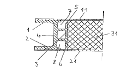
Fig. 4 shows a cross-sectionally Z-shaped border
profile in the installed state. The bearing surface o~
the arm 1 for the top layer 11 i~ on the side remote
from the connection crosspiece 4, while that of the arm
2 for the top layer 21 i8 on the side facing the
CA 02229808 1998-02-17
connecting crosspiece. In the regions between the arms
1, 2 and the core layer 31, the open channels 7, 8 are
shown. With the free surfaces of the arms 1, 2 and of
the connecting crosspiece 4, the composite element is
able to lie, for example, on other structural components
without exerting stress on the top layers 11, 21. One
top layer, 11, finishes with the outer edge of the arm
1, the other top layer, 21, finishing flush with the
core layer 31.
Fig. 5 shows in principle the same arrangement
as Fig. 4, except that one top layer, 11, is bent with
its border 12 by about 180~ around the outer edge of the
arm 1, and the other top layer, 21, continues up to a
shoulder in the region of the channel 8.
Fig. 6 shows a similar arrangement as Fig. 5,
although additionally a groove 22 i5 made in the free
surface of the arm 2, it being possible to insert, for
example, an elastic seal into this groove.
Fig. 7 ~hows diagrammatically the adhesive
bonding of core layer, top layer and border profiles as
in Fig. 4 to ~orm a composite element. The individual
parts are arranged on a solid substrate 23 and covered
with a flexible airtight film 13. The space between
substrate and film is evacuated so that the external air
pre~sure compresses the arrangement and the air present
between the individual parts is able to escape through
the channels 7, 8.
Fig. 8 shows in perspective the individual parts
of a composite element, namely a border profile as in
Fig. 4 with the two arms 1, 2 and the bearing surface 3
for the core layer, the top layers 11, 21 and the core
layer 31. Slots 32 are made on the top and bottom side
of the core layer 31, only one of each of these slots
being shown in the diagram. The slots 32 extend
CA 02229808 1998-02-17
... .
- 13 -
approximately at right angle~ to the longitll~;
direction o~ the border pro~ile.