Note: Descriptions are shown in the official language in which they were submitted.
CA 02229816 1998-02-18
W O 97/08765 PCT~US96/13467
BIE2~DED POLYl~' GEL EIE:CTROLYI~S
Te~hr ir~l Field
~; This invention relates in general to the field of electrolytes for
electrochemical cells, and more particularly to polymer electrolytes for
such cells.
R~ ~ ~u~d of the Inve;lltion
There has been a great deal of interest in developing better and ~nore
efficient methods for storing energy for applications such as radio
comT~unication, satellites, portable computers, and electric vehicles to
name but a few. Accordingly, there have been recent concerted efforts to
develop high energy, cost effective batteries having improved performance
1~ characteristics.
Rechargeable, or secondary cells are more desirable than primary
(non-rechargeable) cells since the associated chemical reactions which
take place at the positive and negative electrodes of the battery are
reversible. Electrodes for secondary cells are capable of being regenerated
ao (i.e. recharged~ many times by the application of an electrical charge
thereto. Numerous advanced electrode systems have been developed for
storing electrical charge. Concurrently, much effort has been dedicated to
the development of electrolytes capable of enhancing the capabilities of
electrochemical cells.
Heretofore, electrolytes have been either liquid electrolytes as are
found in conventional wet cell batteries, or solid films as are available in
newer, more advanced battery systems. Each of these systems have
inherent limitations, and related deficiencies which make them
unsuitable for various applications.
Liquid electrolytes, while demonstrating acceptable ionic
conductivity, tend to leak out of the cells into which they are sealed. While
better manufacturing techniques have lessened the occurrence of leakage,
cells still do leak potentially dangerous liquid electrolytes from time to
time. This is particularly true of current lithium ion cells. Moreover, any
leakage in the cell lessens the amount of electrolyte available in the cell,
thus reducing the effectiveness of the cell. Cells using liquid electrolytes
are also not available for all sizes and shapes of batteries.
CA 02229816 1998-02-18
W O 97/08765 PCTrUS96/13467
Conversely, solid electrolytes are free from problems of leakage.
Howevel-, they have vastly inferior properties as compared to liquid
electrolytes. For example, co~ventional solid electrolytes have ionic
conductivities in the range of 10-5 S/cm (Siemens per c~ntimeter).
Whereas acceptable ionic conductivity is > 10-3 S/cm. Good ionic
conductivity is necessary to ensure a battery system capable of delivering
usable amounts of power for a given application. Good conductivity is
necessary for the high rate operation demanded by, for ~mple, cellular
telephones and satellites. Accordingly, solid electrolytes are not adequate
1~) for many high pelroLmance battery systems.
While solid electrolytes are intended to replace the comhin~ion of
liquid electrolytes and separators used in conventional batteries, the
limitations described hereinabove have prevented them from being fully
implamented. One class of solid electrolytes, specifically gel electrolytes,
16 have shown some promise. Gel electrolytes contain a significant fraction
of solvents (or plasticizers) in addition to the salt and polymer of the
electrolyte itself. One processing route that can be used to assemble a
battery with a gel electrolyte is to leave out the solvent until after the cell is
fabricated. The cell may then be immersed in the solvent and a gel is
ao formed as the solvent is absorbed. Two problems, however, may arise
during solvent absorption: (1) the gel electrolyte may lack sufficient
mechanical integrity to prevent shorting between the electrodes; and/or (2)
~ces.sive swelling accompanies the gel formation. Each of these problems
is a significant limitation to the successful implemenk~tion of gel
2~ electrolytes in electrochemical cells.
Accordingly, there exists a need for a new electrolyte system which
comhines the properties of good mechanical integrity, as well as the ability
to absorb sufficient amounts of liquid electrolytes so as to produce an
electrolyte with the high ionic conductivity of liquid electrolytes. The
30 electrolytes so formed should also avoid excessive swelling, and all the
problems associated therewith
BriefDesc~ip~on of 1;he D~w~
FIG. 1 is a s-hem~tic representation of an electrochemical cell in
35 accordance with the instant invention;
FIG. 2 is a chart illustrating the weight increase in percent for
various polymer and polymer blend materials as a ~unction of time;
CA 02229816 1998-02-18
W O 97/08765 PCTrUS96/13467
FIG. 3 is a photograph, taken with optical microscopy illustrating
the structure of the polymer blend electrolyte system support structure in
accordance with the instant inventiom; and
FIG. 4 is a chart illustrating a series of charge/discharge curves for
5 an electrochemical cell iIlcorporating a polymer blend support structure
in accordance with the instant invention.
Detailed Descrip~on of 1~he I~ ~nt
While the specification concludes with claims defining the features
10 of the invention that are regarded as llovel, it is believed that the invention
will be better understood from a consideration of the following description
in conjunction with the dlawillg figures, in which like reference
numerals are carried forward.
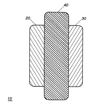
Referring now to FIG. 1, there is illustrated therein a srhem~tic
lEj repres~nt~t.ior of an electrochemical cell in accordance with the instant
invention. The cell 10 includes a positive electrode 20 and a negative
electrode 30. The positive electrode 20 may be fabricated of any of a number
of chemical systems known to those of ordinary skill in the art. Exa~nples
of such systems include mAn~Anese oxide, nickel oxide, cobalt oxide,
ao vanadium oxide, and comhin~t,ions thereof. The negative electrode 30 may
likewise be fab~icated from any of a number of electrode materials known
to those of ordinary skill in the art. S,election of the negative electrode
material is dependent on the selection of the positive electrode so as to
assure an electrochemical cell which will function properly for a given
2~ application. In this context, the negative electrode may be fabricated from
alkali metals, alkali metal alloys, carbon, graphite, petroleum coke, and
comhinAtions thereof. The types of negative and positive electrode
materials recited above are typically associated with lithium battery cells.
It is to be noted however that the invention is not so limited; the blended
30 polymer electrolyte system of the instant invention may be advantageously
employed with nickel-cadmium, nick,el-metal hydride, lead-acid, or any
other battery system.
Operatively disposed between the positive 20 and negative 30
electrodes is an electrolyte system 40. The electrolyte system 40 comprises
3~ a polymer blend including at least two polymers adapted to function as a
support structure and an electrolyte active species. The electrolyte act*e
species may be either a liquid or solid, and may further include a
CA 02229816 1998-02-18
W O 97/08765 PCTAJS96/13467
plasticizer or solvent. Preferably, the electrolyte active species is a liquid
electrolyte adapted to promote ion transport between the positive and
negative electrodes, which liquid is absorbed into the blended polymer
support structure.
As noted above, in the fabrication of polymer gel electrolytes, two
problems arise during solvent absorption. The first problem relates to the
lack of sufficient mechanical integrity to prevent electrical shorting
between the electrodes and the second problem relates to excess*e
swelling which often accompanies the gel formation as the polymer is
10 being immersed in the liquid electrolyte species. The instant polymer
blend electrolyte system solves these problems by providing a polymer
blend, such as a two phase polymer blend~ in which at least one polymer is
provided for purposes of absorbing the electrolyte active species, while at
least a second polymer, which either does not absorb electrolytes or at best
16 absorbs very little electrolyte, provides mechanical integrity. As the
mechanical integrity is improved, shorting between the electrodes is
reduced or elimin~ted.
In addition to improving the mechanical integ~ty of the electrolyte,
the second polymeric phase reduces the rate of electrolyte absorption. By
20 slowing the rate of absorption, excess*e swelling can be avoided and
hence the problems encountered in the prior art devices. It is to be
understood that while the system is described above refers to two phases,
the invention is not so limited. Indeed, the polymer blend electrolyte
system may be a multiphase system in which one or more phases
2~ contribute to electrolyte active species absorption, and one or more phases
contributes to improved mechanical integrity. The operative distinction
however is the presence of discrete phases in a polymer blend, as opposed
to the co-polymers common in other polymeric electrolyte systems.
The liquid electrolyte absorbed by the support structure is selected to
30 optimize performance of the positive 20 and negative 30 electrode couple.
Thus, for lithium type cells the liquid electrolyte absorbed by the support
structure is typically a solution of an alkali metal salt, or combination of
salts, dissolved in a non-protonic organic solvent or solvents. Typical
alkali metal salts include, but are not limited to, salts having the fo~mula
3~ M+X- where M+ is an alkali metal cation such as Li+, Na+, K+ and
comhin~tions thereof; and X~ is an anion such as Cl-, Br~, I-, C104-, BF4-,
P1~6-, ASF6-~ SbF6-, CH3C02-, CF3S03-, (cF3o2)2N- (CF3S02)2N-,
CA 02229816 1998-02-18
W O 97/08765 PCT~US96/13467
(CF3SO2)3C-, and comhin~t.ions thereof. Non-protonic organic solvents
include, but are not limited to, propylene carbonate, ethylene carbonate,
diethyl carbonate, dimethyl carbonate, dipropyl carbonate, dimethyl
sulfoxide, acetonitrile, dimethoxyethane, diethoxyethane,
tetrahyd~oîuran, and combinations thereof. For other electrode
combinations, other electrolyte active species are preferred, such as KOH,
may be emLployed.
Referring now to FIG. 2, there is illustrated therein a chart
describing the weight increase in percent of various polymer gel
10 electrolyte materials versus time. This chart specifically illustrates the
differences found for common homopolymers and copolymers versus
polymer blends according to the instant invention. Accordingly, as is
shown by line 52, a low crystallinity polyvinylidene fluoride (PVDF)
homopolymer known as KYNAR~)461 (Kynar is a registered trademark of
15 Elf Atochem North America, Inc.) demonstrated e~ el.-ely high
increases in weight with the absorpti~n of liquid electrolytes in a relatively
short period of time. Electrolyte absorption is so high as to cause the
resulting gel to expand into the electrodes. This expansion lowers
conductivity between the electrodes thereby seriously degrading the
20 electrochemical performance of cells into which the electrolyte is
incorporated. Line 54 illustrates the absorption properties of a
PVDF/polytetrafluoroethylene copolymer (PTFE) known as KYNAR(~)7201.
It may be appreciated from a perusal of FIG. 2, line 54, that lower
electrolyte absorption was demonstrated by the PVDF/PTFE copolymer.
2~ This lower absorption substantially reduced the problems associated with
gel exp~n.cion as experienced by the PVDF homopolymer. However, cells
constructed from this copolyL{ler experienced short circuiting between the
electrodes due to poor mechanical strength of the gel electrolyte.
A polymer blend, as opposed to a copoly3mer, was prepared using a
30 comhin~ti-~n of KYNAR~) 461 and 18~o high density polyethylene (~IDPE).
The polymer blend so synthesized displayed good mechanical strength and
did not absorb excessive electrolyte as maybe appreciated from line ~6 of
FIG. 2. Electrochemical cells constructed using this polymer blend did
not experience shorting during the assembly, and yielded excellent
35 electrochemical performance. It is to be noted that the three examples
described in FIG. 2 employed a liquid electrolyte consisting of lM LiPF6
CA 02229816 1998-02-18
W O 97/08765 PCTAUS96/13467
including a solvent or plasticizer consisting of a 50% propylene carbonate,
and 50% ethylene carbonate.
While FIG. 2 illustrates the use of a polyvinylidene fluoride-HDPE
polymer blend, it is contempl~ted that the concept of using a polymer blend
could easily be extended to other gel electrolyte systems, both aqueous and
non-aqueous, in order to improve mechanical strength and/or limit the
rate of electrolyte absorption. In this regard, the first polymer in the
polymer system or the absorbing or gel forming polymer, may be selected
from the group of polymers including PVDF, polyurethane, polyethylene
oxide, polyacrylonitrile, polymethylmethacrylate, polyacrylamide,
polyvinyl acetate, polyvinylpyrroliclinone, polytetraethylene glycol
diacrylate, copolymers of any of the foregoing, and comhinqtions thereof.
The second component in the polymer blend, i.e., the nonabsorbing
or inert component, may be selected from the group consisting of
polyethylene, polypropylene, polytetrafluoroethylene, polystyrene,
polyethyleneterephthalate, ethylene propylene diene monomer, nylon, and
combinations thereof. In this regard, it should be noted that at least one
polymer phase in the gel polymer electrolyte acts as a separator in the
liquid electrolyte cell. The phase which acts as the separator is typically
2~) also the phase which provides mechanical stability to the entire electrolytesystem. With respect to the relative amounts of each polymer in the blend,
it is contemplated that the second or non-absorbing component may
comprise between 10 and 40% of the polymer systems, and preferably
between 15 and 25%.
Referring now to FIG. 3, there is illustrated a photograph of a
polymer blend of PVDF and HDPE in accordance with the instant
invention. The photograph is taken with optical microscopy in which the
image is m~gTlified 50x. As maybe appreciated from FIG. 3, two separate
phases of polymers are present in the polymer blend of the instant
invention. In FIG. 3, the electrolyte absorbing phase (PVDF) is identified
by groupings or areas 80, 82, 84, 86, 88, while the non-absorbing polymer
(HDPE) phase is identified by ~rou~ gs or areas 90, 92, 94, 96, 98. It may
thus be appreciated that the polymer system of the instant invention is a
two-phase system as opposed to a copolymer such as that typically used in
36 the prior art.
CA 02229816 1998-02-18
W O 97/08765 PCTAUS96/13467
The invention may be filrther appreciated by the comparative
examples provided hereinbelow.
-
EX:AMPLES
Swelling analysis was conducted on a number of homopolymers,
copolymers, and polymer blends in accordance with the instant invention.
Each of the polymers was swelled in 100~C lM PF6 in a 50~o-50~o solution
of propylene carbonate/ethylene carbonate (PC/EC) solvent. The results
are illustrated in the table below:
Product l~me Wei~t Thi-l~s~ Co .. ~ nt
KYNAR 461 0 9.1 mg 59,um
30 sec 11.7mg 63~Lm
2 min 40.1 mg collapsed
5 min
KYNAR 761 0 11.3mg 67,um
30 sec 17.0 mg 86~m
2 min 24.2 mg 82,um folding
5 min 23.4mg folded
KYNAR 7201 0 11.5 mg 66~m
30 sec 19.4 mg pressed into mesh
2 min 22.9 mg pressed into mesh
5 min gooey-dissolving not
embedded in mesh
82:18 0 11.6mg 59,um
KYNAR 461: 30 sec 12.3 mg 62~mSlight puckering
HDPE 2 min 18.0 mg 65,umSlight puckering
5 min 25.7 mg 91~mSlight puckering
75:25 0 9.5 mg 61~
KYNAR 461 30 sec 12.4 mg 80,unnirregular surface
LDPE 2 min 16.1 mg 87~m
5 min 16.3 mg 87,um
CA 02229816 1998-02-18
W O 97/08765 PCT~US96/13467
~g~lMoPIJE I
Polymer blends were produced using a bench top extruder heated to
temperatures between 150 and 200~ C. Polymer blend films were produced
by hot pressing polymer blends between polished metal plates, at
temperatures between 150 and 200~ C. Homopolymer films of Kynar 461
and Kynar 761 as described above demonstrated significant uptake of
liquid electrolyte act*e species (lM LiPF6 in a 50%-50% solution of PC/EC),
but generally poor mechanical properties and tended to tear easily. Kynar
461 in particular collapsed as the electrolyte active species content
lD exceeded 75%. The PVDF/PTFE copolymer, Kynar 7201, likewise showed
poor mechanical properties.
By bl~ntlin~ the homopolymer (Kynar 461) with either LDPE or
HDPE the electrolyte absorption was reduced; however, mechanical
properties were substantially improved. For example, after five minutes
15 the 75:25 Kynar 461/LDPE blend absorbed 42% of the electrolyte active
species (again lM LiPF6 in a 60%-50% solution of PC/EC), while the 82:18
Kynar 461:HDPE blend absorbed 55% of the electrolyte active species.
Impedance measurements were carried out for each sample, to determine
the ionic conductivies of the films. For the 75:25 Kynar 461/LDPE blend,
20 conductivity measured lx10-4 Siemens per c~ntim~ter (S/cm), while
conductivity for the 82: 18 Kynar 461:HDPE blend was 6x10⁻⁴ S/cm. The
conductivity of the 82: 18 Kynar 461:HDPE blend is particularly suitable for
application in lithium electrochemical cells, as is shown in ~,~Ample II
below.
2~ MpLE II
To demonstrate the suitability of a blended polymer electrolyte for
application in lithium ion cells, a cell was constructed using a petroleum
coke anode and a LiCoO2 cathode. The polymer blend electrolyte system
comprised the 82:18 Kynar 461:HDPE blend, soaked in lM LiPF6 in a 60%-
3Q 50% solution of PC/EC. The electrodes were prepared by mi~rin~ and hotpressing powders with the following compositions:
anode: 81% petroleum coke, 19% Kynar 461
cathode: 73% LiCoO2, 16% graphite, 12% Kynar 461.
A cell was formed by lAmin~ting the electrodes to the blended
35 polymer. A copper mesh current collector was used for the anode and an
aluminum mesh current collector for the cathode. The liquid electrolyte
CA 022298l6 l998-02-l8
W O 97/08765 PCTrUS96/13467
active species was introduced by soaking in the solution at 100~C. The
resulting electrode ~limen.~ions were 1.8cm x 2.0cm x 130,um.
A cell so fabricated was cycled at 1.0 milli~qmpfi (mA~ between 4.2
and 2.7 volts, with one hour rests between each charge/discharge cycle.
ReferIing now to FIG. 4, there is illustrated therein the charge/discharge
J profiles for the first ten cycles of the cell fabricated according to this
example. As may be appreciated from a perusal of FIG. 4, the cell
demonstrated good cell ~evef~ibility and overall good cell performance
using the blended polymer electrode.
1() While the l)~efelfed embodiments of the invention have been
illustrated and described, it will be clear that the invention is not so
limited. Nllmerous modifications, changes, variations, substitutions and
equivalents will occur to those skilled in the art without departing from
the spirit and scope of the present invention as defined by the appended
~5 claims.
What is claimed is: