Note: Descriptions are shown in the official language in which they were submitted.
CA 02230012 1998-03-27
FIELD OF THE INVENTION
The present invention reiates generally to a device and method for
treating a blockage or stenosis in a vessel of a patient. More specifically, thepresent invention relates to a device and method for precisely delivering a
5 dosaqe of radiation to a vessel to inhibit re-stenosis.
BACKGROUND
It is well known that many medical complications are caused by a
partiall or total blockage or stenosis of a blood vessel in a patient. Dependingon the location of the stenosis, the patient can experience cardiac arrest,
10 stroke or necrosis of tissues or organs. Commonly, the stenosis is caused by
the build-up of artherosclerotic plaque in the intima of the vessel. The plaque
typically builds up irregularly in the vessel As a result of the irregular build-
up of plaque, the lumen of the vessel, in most blocked vessels, is not
centrally located relative to the external elastic lamina.
Several procedures have been developed to treat stenoses, including
angioplasty, stenting, and atherectomy. However, none of these procedures
are entirely successful in inhibiting or preventing the re-stenosis of a vessel
after the procedure is completed.
Recent studies have demonstrated that radiation may inhibit or prevent
20 re-stenosis in the vessel by inhibiting or preventing the growth of fibrotic cells
in the vessel wall, commonly referred to as neointima. The precise target for
the raciiation in the vessel is currently not known. However, it is believed that
the adventitia may be a key source of growth of the neointima. Therefore. it
CA 02230012 1998-03-27
.
is theorized that the entire vessel, including the adventitia should be treated
with radiation.
At least one delivery device has been used for performing
intravascular radiation treatment on a treatment site of the vessel. This
delivery device utilizes a catheter to position a radiation source in the vessellumen, adjacent the treatment site. The radiation source is positioned in the
vessel lumen and is allowed to emit radiation until the proposed dosage is
released. With this delivery device, the tissue closest to the radiation source
receives a larger radiation dosage than the tissue farthest from the radiation
source. Subsequently, the radiation source is removed from the vessel
lumen.
However, the results obtained using this type of delivery device are not
entirelly satisfactory. Specifically, because the growth of the plaque inside
the vessel is irregular andlor the vessel is curved, the radioactive source is
not centered in the vessel relative to the vessel lamina. Thus, depending
upon the dosage prescribed, this can result in undertreating certain portions
of the vessel and overtreating certain other portions of the vessel. For
example, certain portions of the vessel lamina will receive a larger dosage of
radiation than other portions of the vessel lamina.
Undertreating with radiation can result in not inhibiting the neointima
and, in some instances, can actually result in stimulating smooth muscle cell
proliferation and extra-cellukar matrix production. Overtreating with radiation
can, for example, induce nec;rosis or aneurysm. Therefore, it is important to
avoid overtreating and/or unclertreating of a treatment site of the vessel.
One attempt to solve this problem involves accurately centering the
delivery device in the vessel, relative to the vessel lumen. This can be
accorrlplished using a variely of mechanical devices, such as a centering
balloon or an expandable rnechanical strut. However, these mechanical
CA 02230012 1998-03-27
devices add excessive mass and bulk to the delivery device. This limits the
usefulness of the present delivery device to relatively large vessels, i.e., 3.5millirrleters or larger and increases the risk of occluding blood flow in the
vessel. Moreover, there is a risk that the delivery device will not be
5 accurately centered.
In light of the above, it is an object of the present invention to provide a
device and method for delivering a precise dose of radiation to a treatment
site of a vessel without centering the delivery device. It is another object of
the present invention to provide a device and method for delivering a
10 substantially uniform dose of radiation to the vessel lamina and other areas of
the ve!ssel. Still another object of the present invention is to provide a device
and method which is relatively safe and easy to use. Yet another object of
the present invention is to provide a device which is relatively simple and
inexpensive to manufacture.
1 5 SUMMARY
The present invention is directed to a delivery device which satisfies
these objectives The delivery device is useful for delivering a dose of
radiation from a radiation source to a treatment site of a vessel to treat a
stenosis in the vessel. The delivery device includes a catheter and a delivery
.20 area which insert into the vessel. As provided herein, the delivery area
includes an attenuator section which attenuates the intensity of a portion of
the radiation emitting from the radiation source when a portion of the
radiation source is positioned in the delivery area. In use, the attenuator
section partly inhibits the intensity of radiation directed at where the vessel
25 wall is the thinnest. This prevents overtreatment of the vessel.
CA 02230012 1998-03-27
As used herein, the term "radiation dose profile" refers to and means
the cross-sectional pattern of energy being delivered from the delivery area of
the clelivery device. A more comprehensive definition of radiation dose
profile is provided in the description section.
As used herein, the term "vessel wall" refers to and means the
structural support of the vessel. For an artery, the vessel wall would include
an endothelium, a basement membrane, a vessel intima, an eternal elastic
lamina, a vessel media, a vessel external elastic lamina (hereinafter "vessel
lamina"), and a vessel adventitia. For a diseased artery, the vessel wall can
10 also include atherosclerotic plaque which infiltrates the vessel intima and
causes stenosis of the vessel.
As provided in detail below, since the attenuator section attenuates a
portion of the radiation emitl:ing from the radioactive area, the delivery area
emits a radiation dose profile which is substantially eccentric. With an
15 eccentric radiation dose profile, more radiation can be directed at where thevessel wall is the thickest, while less radiation can be directed to where the
vessell wall is the thinnest. This can be accomplished by rotating the delivery
area until the attenuator section is substantially closest to the vessel lamina.Since, the attenuator section attenuates a portion of the radiation directed at
20 where the vessel wall is the thinnest, a substantially uniform dosage of
radiation is delivered to the vessel lamina at the treatment area, even though
the delivery device is not centered in the vessel relative to the vessel lamina.The attenuator section includes an attenuator material which at least
partly diminishes the intensity of the radiation which emits therefrom. The
25 attenuator material is typically a relatively dense material having a relatively
high atomic number. Preferably, the attenuator material is also bio-
compaltible and safe for use in surgery. Materials such as gold, platinum, and
tantalum can be used.
CA 02230012 1998-03-27
Importantly, the shape of the radiation dose profile varies according to
the size, shape, and thickness of the attenuator section, as well as the
attenuator material utilized. Thus, the attenuator section can be designed so
that the radiation dose profile corresponds to the specific size and shape of
5 the vessel wall. As used herein, the phrase "configuration of the attenuator
section" shall mean the size, shape, thickness, and material utilized in the
attenuator section. Also a; used herein the phrase "configuration of the
vessel wall" shall mean the size and shape of the vessel wall at the treatment
site, including the positioning of the vessel lamina relative to the vessel
1 0 lumen.
The delivery device also includes a catheter supporter which
substantially inhibits rotational deformation in the catheter between a catheterdistal end and a catheter proximal end. The catheter supporter allows the
delivery area to be precisely rotated by the catheter proximal end to position
15 the filter section adjacent where the vessel wall is the thinnest.
Preferably, the delivery device includes at least one marker positioned
proximate the delivery area. The marker is used to indicate the location of
the delivery area in the vessel. For example, the marker can be radiopaque
and visible with a fluoroscope. This allows the doctor to position the delivery
20 area adjacent the treatment area.
The invention is also al method for delivering radiation from a radiation
source to a treatment site of a vessel. The method includes the steps of
advancing a catheter into the vessel lumen until a delivery area is positioned
substantially adjacent the tre.atment site, positioning at least a portion of the
:25 radiation source proximate the delivery area, and emitting a radiation dose
profile from the delivery area which is substantially eccentric.
Further, the method can include the step of rotating the delivery area
inside the vessel lumen unl:il the orientation of the attenuator section is
CA 02230012 1998-03-27
substantially closest to the vessel lamina. This step typically includes
imaging the vessel to determine when a window section of the delivery area
is substantially farthest away from the vessel lamina.
Preferably, the treatment site of the vessel is imaged to determine the
configuration of the vessel wall proximate the treatment site. With this
inforrrlation, the configuration of the attenuator section can be chosen.
It is important to recognize that a device in accordance with the
present invention utilizes an attenuator section proximate the delivery area so
that the delivery area emits a radiation dose profile which is substantially
10 eccentric. Therefore, the delivery device is able to deliver a substantially
uniforrn dose to the vessel lamina, even though the delivery device is not
centered relative to the vessel lamina.
BRIEF DESCRIPTION OF THE DRAWINGS
The novel features of this invention, as well as the invention itself, both
15 as to its structure and its operation will be best understood from the
accompanying drawings, taken in conjunction with the accompanying
description, in which:
Figure 1 is a top plan view of a patient with a delivery device having
features of the present invention positioned in a vessel of the patient;
Figure 2 is an exploded, side plan view of a delivery device having
features of the present invention;
Figure 3 is a cross-sectional view of a prior art delivery device
positioned in a vessel;
Figure 4 is a cross-sectional view of a delivery device having features
25 of the present invention positioned in a vessel;
CA 02230012 1998-03-27
Figure 5 is an enlarged view, in partial cutaway, of a portion of a
delivery device having features of the present invention;
Figure 6A is a cross-sectional view of a first embodiment of a catheter
supporter taken on Line A-A in Figure 2;
5Figure 6B is a cross,-sectional view of the first embodiment of the
catheler supporter taken on l ine B-B in Figure 2;
Figure 6C is a cross-sectional view of the first embodiment of the
catheler supporter taken on l ine C-C in Figure 2;
Figure 7A is a cross-sectional view of a second embodiment of a
10catheter supporter taken on l ine A-A in Figure 2; and
Figure 8 is an enlarged, perspective view of a portion of an attenuator
section having features of the present invention.
DESCRIPTION
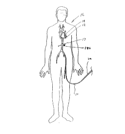
Referring initially to Figure 1, a delivery device 10 for delivering a
15dosage of radiation to a treatment site 12 of a vessel 14 of a patient 16 is
provided herein. The delivery device 10 is useful from treating a vessel wall
18 (shown in Figures 3 and 4) of a vessel 14 throughout the vascular system
of the patient 16 Although the present invention is particularly useful for
inhibiting the re-growth of neointima in coronary arteries, it is anticipated that
:20the present delivery device 10 can be used to treat medical conditions, such
as cancer 1 7, proximate the vessel 1 4b .
The delivery device 10 may be introduced into the vessel 14 wherever
it is convenient. As shown in Figure 1, the delivery device 10 can be inserted
through an external, flexible, tubular shield 20 which partly inhibits the
25 intensity of radiation. The tubular shield 20 diminishes the potential of
CA 02230012 1998-03-27
radiation exposure to the medical staff during use of the present delivery
device 10.
A guiding catheter (not shown) is typically used with the present
delivery device 10 for the treatment of coronary arteries. A suitable guiding
5 cathel:er is sold by Medtronic of Minneapolis, Minnesota.
The structural details of the delivery device 10 may be more fully
appreciated by reference to F igure 2, where the delivery device 10 includes a
catheter 22, a delivery area 24, a catheter supporter 26 (not shown in Figure
2), a guide wire 28 and a radiation source 30 having a radioactive area 32.
As provided in detail below, the unique design of the delivery area 24
allows the doctor to control the radiation emitting from the delivery area 24
when the radioactive area 32 is positioned in the delivery area 24. Basically,
the delivery device 10 is designed to reduce the intensity of radiation
proximlate where the vessel wall 18 is the thinnest. This allows the doctor to
tailor the radiation treatment to suit the configuration of the vessel wall 18 at
the treatment site 12. Further, this allows the doctor to deliver a substantially
unifornn dose of radiation to a vessel lamina 34 to inhibit the growth of
neointima in the vessel 14.
It is anticipated that the present delivery device 10 will be used in
conjunction with other vascular procedures such as angioplasty, stenting,
and/or atherectomy for the treatment of a stenosis 33 in the vessel 14.
However, the present device 10 can also be used in lieu of these or other
procedures.
Referring to Figures 3 and 4, the vessel wall 18 includes the stenosis
33, a vessel lamina 34, and a vessel adventitia 35. The configuration of the
vessel wall 18 defines the size and shape of a vessel lumen 36 and the
location of the vessel lumen 36 relative to the vessel lamina 34. In the vessel
14 shown in Figures 3 and 4, the vessel wall 18 is irregular and oblong
CA 02230012 1998-03-27
shaped. Thus, the vessel lumen 36 is offset from center and eccentrically
positioned relative to the vessel lamina 34. Therefore, the delivery device 10
positioned in the vessel lurnen 36, is offset from center and eccentrically
positioned relative to the vessel lamina 34. It should be noted that the vessel
lumen 36 represented in Figures 3 and 4 is the resulting vessel lumen 36
affer an angioplasty treatment.
There is considerable debate about the amount of radiation that
shouki be delivered to the vessel 14 to inhibit the growth of neointima. The
present delivery device 10 is designed to deliver a dosage of approximately
10 ten (10) to twenty (20) gray of radiation to the vessel lamina 34. However,
the present invention is not Intended to be limited to these dosages and the
dosages provided herein are only exemplary. For example, additional
research may determine that dosages of more than or less than ten (10) to
twenty (20) gray may be more beneficial to the patient 16.
As used herein, the term radiation dose profile refers to and means the
cross-sectional pattern of energy being delivered by the delivery area to the
vessel 14. The approximate shape of the radiation dose profile is
represented by a plurality of dose curves 37A-F shown in Figures 3 and 4
Each dose curve 37A-F represents an approximate area in the vessel 14
which is receiving a substantially uniform dosage of radiation. For example,
dose curve 37A can represent the area in the vessel 14 which receives a
dosage of approximately thirty (30) gray, dose curve 37B can represent the
area in the vessel 14 which receives a dosage of approximately twenty-five
(25) gray, dose curve 37C can represen~: the area of the vessel 14 which
receives a dosage of approximately twenty (20) gray, dose curve 37D can
represent the area of the vessel 14 which receives a dosage of approximately
fifteen (15) gray, dose curve 37E can represent the area in the vessel 14
which receives a dosage of approximately ten (10) gray, and dose curve 37F
CA 02230012 1998-03-27
can represent the area in the vessel 14 which receives a dosage of
approximately five (5) gray.
Figures 3 shows the close curves 37A-F from a prior art delivery device
39. F-or the prior art delivery device 39, the radiation emits equally radially
from l:he radioactive area 32. Thus, the dose curves 37A-F in Figure 3, are
substantially circular and concentric.
From Figure 3, it can be seen that the vessel lamina 34 does not
receive a substantially uniform dosage. In fact, portions of the vessel lamina
34 receive a dosage of approximately twenty (20) gray while other portions of
the vessel lamina 34 receive a dosage of less than five (5) gray. Thus,
depending upon the actual dosage utilized, portions of the vessel lamina 34
may be undertreated, while other portions of the vessel lamina 34 will be
overtreated.
Figure 4 shows the dose curves 37A-F for a delivery device 10 having
features of the present invention. Because of the unique design of the
delivery area 24, the dose curves 37A-F in Figure 4 are not circular. In fact
the dose curves 37A-F in Figure 4 are substantially elliptical or eccentric As
a result thereof, referring to dose curve 37D of Figure 4, the entire vessel
lamina 34 receives a substantially uniform dose of approximately fifteen (15)
gray, even though the delivery area 24 is not centered relative to the vessel
lamincl 34.
The catheter 22 inserts into the vessel 14 and is used to position the
radioactive area 32 adjacent the treatment site 12. The catheter 22 includes
a tubular outer structure 38 having a catheter distal end 40 and a catheter
.25 proxirrlal end 42. The catheter distal end 40 inserts into the vessel lumen 36
and should be as smooth as possible to facilitate insertion into the vessel
lumen 36. The catheter proximal end 42 typically remains outside the patient
16. A~; shown in Figure 2, the catheter proximal end 42 can include a handle
CA 02230012 1998-03-27
44 which is used to manipulate and rotate the catheter 22 in the vessel lumen
36.
The outer structure 38 can be made from a variety of materials, such
as a block copolymer sold under the trademark Pebax by Elf Atochem North
American located in Philadelphia, Pennsylvania or polyethylene. Preferably,
the outer structure 38 is coated with a hydrophilic or other lubricious coating
to facilitate easy movement of the catheter 22 in the vessel lumen 36.
Referring to Figures ';, 6A-C and 7A, the catheter 22 also includes a
guide wire lumen 46 for receiving the guide wire 28. The guide wire lumen
46, shlown in the Figures, is defined by a guide wire tube 47 having an inner
diameter of between about 0.015 to 0.025 inches. The guide wire lumen 46
extends from the catheter proximal end 42 to the catheter distal end 40.
Referring again to Figures 5, 6A-C and 7A, the catheter 22 further
includes a delivery lumen 48 which is sized and shaped to receive the
radiation source 30. Thus, the size and shape of the delivery lumen 48
depends upon the size and shape of the radiation source 30. In the
embociiment shown in the Figures, the delivery lumen 48 is defined by a
delivery tube 49 having an inner diameter of between about 0.02 to 0.03
inches.
The delivery lumen 48 extends from the catheter proximal end 42 to
proximlate the catheter distal end 40. The delivery lumen 48 can be sealed
proximate the catheter distal end 40 to prevent the radiation source 30 from
escaping into the vessel 14 and to prevent direct contact between the blood
(not shown) in the vessel 14 and the radiation source 30. Alternately, the
:25 delivery lumen 48 can be open proximate the catheter distal end 40.
The delivery tube 49 and the guide wire tube 47 can be made from a
number of materials, including a block copolymer or a high density
polyethylene.
CA 02230012 1998-03-27
It is anticipated that the catheter 22 can also include a bypass lumen
(not shown) for transporting blood (not shown) in the vessel 14, past the
cathelter 22, when the catheter 22 is positioned in the vessel 14. Basically,
the bypass lumen allows the delivery device 10 to be used in relatively small
5 vessels 14 without interrupting blood intensity in the vessel 14.
The delivery area 24 receives the radioactive area 32 and delivers the
radiation to the treatment site 12. As provided herein, the unique design of
the delivery area 24 allows the delivery area 24 to emit a radiation dose
patten1 which is substantially eccentric and elliptical. Thus, a substantially
10 homogenous radiation dose can be delivered to the vessel lamina 34 even
though the delivery device 10 is eccentrically positioned relative to the vessellamina 34.
The length and positioning of the delivery area 24 can be varied to
meet the needs of the patient 16. In the embodiment shown in Figure 5, the
15 delivery area 24 is approximately one half to ten (0.5-10) centimeters long
and is positioned proximate the catheter distal end 40.
The delivery area 24 includes an attenuator section 50 and a window
section 52 for directing the intensity of radiation emitting from the radioactive
area 32. Basically, the attenuator section 50 alters the pattern of radiation
20 emitting from the delivery area 24 This compensates for the irregular shape
of the stenosis 18 and for the eccentric positioning of the delivery area 24
relative to the vessel lamina 34.
The attenuator section 50 can be designed to attenuate approximately
between about one percent to one hundred percent (1%-100%) of the
25 intensil:y of the radiation directed toward the attenuator section 50. In
contrast, the window section .52 can be designed to attenuate approximately
between zero percent to ninel:y-nine percent (0%-99%) of the intensity of the
radiation directed at the window section 52.
CA 02230012 1998-03-27
In the embodiment de:scribed in detail herein, the attenuator section 50
attenuates a relatively signiFicant amount of radiation directed towards the
attenuator section 50 while the window section 52 has a relatively negligible
or insignificant effect upon the radiation emitting from the delivery area 24.
In this embodiment, the attenuator section 50 attenuates approximately
between ten percent to forty percent (10%40%) of the intensity of radiation
directed at the attenuator section 50 while the window section 52 attenuates
less than approximately one percent (1%) of the intensity of the radiation
directed at the window section 52.
Importantly, it is the difference in the amount of attenuating between
the window section 52 and the attenuator section 50 that is significant in
determining the radiation dose profile. Conceivably, the attenuator section
50 can attenuate between about one percent to one hundred percent (1%-
100%) more radiation than the window section 52 to create dose curves 37A-
F which are not circular. Typically, for most situations, the attenuator section50 is ciesigned to attenuate about five percent to ninety percent (5%-90%)
and rr~ore preferably about ten percent to forty percent (10%40%) more
radiation than the window sec,tion 52.
Alternately, to deliver a concentrated dosage of radiation to a specific
:20 area, i.e, cancer 17 proximal:e the vessel 14b, the attenuator section 50 can
be designed to attenuate between about ninety percent and one hundred
percent (90%-100%) mo-e raciiation than the window section 52.
In the embodiment shown in the Figures, the attenuator section 50
includes a portion of the delivery tube 49, a first component 55a and a
seconci component 55b. The first and second components 55a, 55b include
an attenuator material which attenuates the intensity of radiation
therethrough. In contrast, the delivery tube 49 is made of a material which
has a relatively insignificant effect upon the radiation.
CA 02230012 1998-03-27
Importantly, the configuration of the attenuator section 50, i.e., the
size, shape, thickness, and the attenuator material of the attenuator section
50 can be varied to change the shape of the radiation dose profile to suit the
configuration of the vessel wall 18 at the treatment site 12. For example, as
the si;ze and thickness of the attenuator section 50 increases, the radiation
dose profile becomes increasingly more eccentric. Similarly, as the size and
thickness of the attenuator section 50 is decreased, the radiation dose profile
becomes increasingly more c:oncentric.
The attenuator material can be made from a number of materials
and/or alloys which attenuate radiation. Because of the size limitations of the
delivery device 10, the attenuator material is typically a relatively dense
material having a relatively high atomic number. Preferably, to minimize the
size of the attenuator section 50, the attenuator material has: (i) a density ofat least about ten (10) grams per cubic centimeter and more preferably at
least about nineteen (19) grams per cubic centimeter; and (ii) an atomic
number of at least about twelve (12), and more preferably at least about
seventy (70). Further, the attenuator material is preferably bio-compatible so
that the attenuator section 50 is compatible with the vessel 14. It is
anticipated that gold, platinum, or tantalum can be used as the attenuator
material. Alternately, alloys utilizing one or more relatively dense materials
can al ,o be used.
In the embodiment shown in the Figures, the first and second
compcnents 55a, 55b are each a piece of thin foil that is between about one
(1) to l:wo hundred (200) microns and more preferably between about five (5)
:25 to fifty (50) microns thick. Each of the first and second components 55a, 55b
are shlaped similar to a semi-circular band. In this embodiment, the first
component 55a is rolled or wrapped around a portion of the delivery tube 49
while the second component 55b is rolled or wrapped around the first
14
CA 02230012 1998-03-27
component 55a. The first component 55a can be bonded to the delivery tube
49 and the second component 55a can be bonded to the first component 55a
with a suitable adhesive. Alternately, a retaining tubular conduit (not shown)
can be wrapped around and retain the first and second components 55a, 55b
5 to the delivery tube 49.
In the embodiment shown in Figures 4, 6A, 7A, and 8 the first
component 55a extends approximately two hundred degrees (200~) around
the de!livery tube 49 while the second component 55b extends approximately
one hundred and twenty degrees (120~) around the delivery tube 49. It is
10 anticipated that the first component 55a can be designed to extend between
about two hundred degrees to two hundred and seventy degrees (200~-270~),
while the second component 55b extends between about one hundred
degrees to one hundred and fifty degrees ( 100~-150~). Further, the
positioning of the first and second components 55a, 55b can be switched
Alternately, the attenuator section 50 can be implemented in a number
of other ways. For example, the attenuator section 50 can be a thin foil of
varyin(g thickness, which is rolled completely around a portion of the delivery
tube 49. In this embodiment, the foil includes an opening (not shown) which
forms the window section 52. Alternately, the attenuator material can be
20 sputtered and then electroplated directly onto the delivery tube 49 or ion
beam technology can be used to secure the attenuator material to the
delivery tube 49. Further, it is envisioned that the delivery tube 49 could be
impregnated with an attenuator material such as barium.
It is anticipated that a plurality of delivery devices 10 will be provided
25 to the hospital and each delivery device 10 will have an attenuator section 50
with a different attenuator configuration. Thus, the doctor will be able to
choose the delivery device 10 having the radiation dose profile which most
closely matches the configuration of the vessel wall 18.
CA 02230012 1998-03-27
In the embodiments shown in the Figures, the window section 52 is
defined by the portion of the delivery tube 49 which is not covered with the
attenuator material. In this embodiment, the delivery tube 49 is made of a
material which has a negli!3ible or insignificant effect upon the radiation
emitting from the delivery area 24 when compared to the attenuator section
50. In fact, since the attenuator section 50 also includes a portion of the
delivery tube 49, the window section 52 basically has no relative effect upon
the radiation emitting from the delivery area 24.
Since the window section 52 does not reduce the intensity of the
radiation as much as the attenuator section 50, the window section 52
delivers the radiation to a greater depth in the tissue than the attenuator
section 50. This enables the delivery device 10 to preferentially deliver more
radiation to where the vessel wall 18 is the thickest.
Referring back to Figure 4, in use, the delivery area 24 is rotated in the
vessel lumen 36 until the attenuator section 50 is substantially closest-to the
vessel lamina 34, while the window section 52 is farthest from the vessel
lamina 34. Thus, the attenuator section 50 is proximate where the vessel wall
18 is the thinnest while the window section 52 is proximate where the vessel
wall 1~ is the thickest.
:70 The catheter 22 can include a radiation blocker 54 (shown in phantom
in Figure 5) positioned proximate the catheter distal end 40 which inhibits
radiation from emitting longitudinally from the delivery area 24. The radiation
blocker 54, for example, can be a cylindrical disk made from a relatively
dense material such a platinum or gold which is positioned in the delivery
conduit proximate the catheter distal end 40.
Preferably, the delivery device 10 includes a pair of markers 56 which
assist In the positioning of thle delivery area 24 proximate the treatment site
12. Referring to the Figures, the markers 56 can each be a band, made from
CA 02230012 1998-03-27
a radiopaque material, which encircles the outer structure 38 of the catheter
22 on each side of the delivery area 24 Since the markers 56 are made of a
radiopaque material, such as platinum or gold, the position of the markers 56
is visible using a fluoroscope or x-rays.
The catheter supporter 26 inhibits rotational deformation or twisting of
the catheter 22 between the catheter distal end 40 and the catheter proximal
end 42. In use, the catheter supporter 26 transmits torque smoothly and
predictably between the catheter proximal end 42 and the catheter distal end
40. This allows the delivery area 24 to be precisely rotated with the handle
10 44 so that the window section 52 is substantially adjacent where the vessel
wall 18 is the thickest.
The catheter supporter 26 can be implemented in a number of
alternate ways. For example, as shown in Figures 6A-C, the catheter
suppolter 26 can include a pair of spaced apart cylindrical shafts 58
15 positioned within the catheter outer structure 38 and extending substantially parallel with the guide wire lumen 46 and the delivery lumen 48. The
cylindrical shafts 58 are widest proximate the catheter proximal end 40 and
taper towards the delivery area 24.
Alternately, as shown in Figure 7A, the catheter supporter 26 can be a
20 tubular member 60 which encompasses the guide wire lumen 46 and the
delivery lumen 48 The tubular member 60 is positioned within the catheter
outer structure 38 and is conc:entric with the outer structure 38. Similarly, the
tubular member 60 is thickest proximate the catheter proximal end 40 and
tapers towards the delivery area 24. Alternately, those skilled in the art would25 recognize other ways to design the catheter supporter 26.
The catheter supporter 26 must be sufficiently flexible to allow the
catheter 22 to be positionecl in small, curving vessels 14. The catheter
supporter 26 can be made of a number of materials which include a
CA 02230012 1998-03-27
composite of polymer and metallic components. For example, a suitable
catheter supporter 26 can be made from the block copolymer sold under the
tradernark Pebax by Elf Atochem. The catheter supporter 26 provided herein
also inhibits the guide wire lumen 46 and the delivery lumen 48 from
5 collaplsing.
The guide wire 28 is suitable for being inserted into the vessel lumen
36 and is used to guide the delivery area 24 through the vessel lumen 36 to
the treatment site 12. A guide wire 28 having a diameter of about 0.014
inches is commonly used.
Referring to the Figure 2, the radiation source 30 is sized to fit into the
delivery lumen 48 and includes a delivery wire 62 and the radioactive area 32
attached to the delivery wire 62. The radiation source 30 inserts into the
delivery area 24 and remains in the delivery area 24 until the proposed
dosage is released. Thus, the amount of time that the radiation source 30 is
15 positioned in the delivery ,area 24 depends upon the emittance of the
radioactive area 32 and the proposed dosage requirements of the patient 16
Preferably the radioactive area 32 emits ,~-rays since the ,~-rays have a
relatively short tissue penetration level. Because of the short tissue
penetration of ~-rays, the medical staff is exposed to less radiation and the ,~-
20 rays can be controlled within the delivery area 24. Preferably, the radioactivearea 32 also has a relatively high activity level so that the prescribed dose of
radiation emits quickly into the patient 16. For example, for a radioactive
area 32 which includes Rhenium could have an activity level of about 2 to
300 mCi and a usable tissue penetration level of between about 1.5 to 2 5
,75 millimeters.
Typically, the radioactive area 32 is between about 0.5 to 10.0
centimleters in length and has a diameter of between approximately 0.1
1a
CA 02230012 1998-03-27
millimeters to 2.0 millimeters. Additionally, the radioactive area 32 can be
rechargeable and reusable to minimize radioactive waste.
Alternately, it is anticipated that the radioactive area 32 could include
gammla emitters or a non-nuclear source could provide the radioactivity to the
radioactive area 32.
Typically, the deliven~ device 10 is used in conjunction with a first
imaging system 64 which provides an accurate and detailed map or image of
the internal structure of the vessel 14. A suitable first imaging system 64 is
an Intravascular Ultrasound System ("IVUS System") sold by Boston
10 Scienl:ific The IVUS System uses ultrasonic waves to map or image the
vessell 14. Referring to Figure 2, the first imaging system 64 includes a first
imaging catheter 66 which inserts directly into the vessel lumen 36 to image
the structure of the vessel 14.
Further, the delivery device 10 can be used in conjunction with a
15 seconci imaging system 68 which indicates when the delivery area 24 is
properly oriented within the vessel lumen 36. An IVUS System also sold by
Boston Scientific, can be used for the second imaging system 68. Referring
to Figure 2, the second irrlaging system 68 includes a second imaging
catheter 70 which inserts into the delivery lumen 48 to determine when the
20 delivery area 24 is properly oriented. If the second imaging system 68 is an
IVUS System, the delivery lumen 48 must be filled with a substantially
incom~oressible fluid (not shown), such as saline. It is anticipated that the
same IVUS System can be used for the first imaging system 64 and the
second imaging system 68.
Preferably, a sheath 7:2 can be used to protect or isolate the radiation
source 30 from the incompressible fluid Referring to Figure 2, the sheath 72
is tubular cover which inserts into the delivery lumen 48. The sheath 72
provides a barrier and isolates the radiation source 30 from contact with the
19
CA 02230012 1998-03-27
incorrlpressible fluid. The sheath 72 can be made of a thin, high density
polyel:hylene.
As shown in Figure 2, the delivery device 10 can also include a dummy
rod 74 for inserting the sheath 72 into the delivery lumen 48'and insuring that
5 the delivery lumen 48 is not collapsed. The dummy rod 74 is designed to be
substantially identical to the radiation source 30. Basically, the dummy rod
74 is used to install the sheath 72 and insure that the radioactive area 24 willmove smoothly within the delivery lumen 48 to the delivery area 24.
OPERATION
An example of the operation of the delivery device 10 can best be
visualized with initial referenc,e to Figures 1 and 2 First, the guiding catheter
is inserted into the coronaty artery ostium. Next, the guide wire 28 is
positioned into the vessel 14 of the patient 16. This is done to establish a
mechanical pathway through the vessel 14. Subsequently, the first imaging
15 catheter 66 of the first imaging system 64 is inserted into the vessel lumen
36. The first imaging system 64 provides an accurate and detailed map or
image of the internal struclure of the vessel 14. With the information
obtained from the first imaging system 64, the location of the treatment site
12, the size and shape of the vessel wall 18, and the positioning of the vessel
20 lumen 36 relative to the vessel lamina 34 can be determined.
Next, the first imaging catheter 66 is removed and an initial vascular
procedure such as angioplasty, stenting, andlor atherectomy can optionally
be pelformed upon the vessel 14. If an initial vascular procedure is
performed on the vessel 14, the first imaging catheter 66 can be reinserted
25 into the vessel lumen 36 to pn~vide an accurate and detailed map or image of
CA 02230012 1998-03-27
the residual internal structure of the vessel 14. The first imaging catheter 66
is then removed from the vessel lumen 36.
Importantly, the configuration of the vessel wall 18 and the vessel 14
can be determined with infonmation fFom the first imaging catheter 66. Stated
5 another way, the residual size and shape of the vessel wall 18 and the
positioning of the vessel lumen 36 relative to the vessel lamina 34 can be
determined. Based upon configuration of the vessel wall 18, the
configuration of the attenuator section 50, i.e., the shape, size, and thicknessof the attenuator section 50 can be selected to deliver the desired radiation
10 dose profile.
Next, the guide wire lumen 46 of the catheter 22 is moved over the
guide wire 28 until the delivery area 24 is adjacent to the treatment site 12.
The markers 56 on the catheter 22, proximate the delivery area 24, allow the
doctor to precisely determine the location the delivery area 24 using a
15 fluoroscope.
With the delivery area 24 adjacent the treatment site 12, the second
imaging catheter 70 and the incompressible fluid are inserted into the
delivery lumen 48. The second imaging system 68 provides information
about lthe shape of the vesse!l wall 18 through the window section 52. With
20 this inlormation, the catheter proximal end 42 is rotated until the second
imaging system 68 indicates when the delivery area 24 is properly oriented,
i.e., the window section 52 is adjacent where the vessel wall 18 is the
thickest. Importantly, the catheter supporter 26 transmits torque smoothly
and predictably between the catheter proximal end 42 and the catheter distal
25 end 4CI. This allows for the precise orientation of the window section 52
adjacent the thickest area of the vessel wall 18 at the treatment site 12 and
prevents collapse of the delivery lumen 48.
~ CA 02230012 1998-03-27
Subsequently, the c:atheter 22 is retained in this orientation and the
second imaging catheter 7() is removed from the delivery lumen 48.
Next, the sheath 72 is installed with the dummy rod 74 into the delivery
lumen 48. The dummy rod 74 is then removed and the sheath 72 remains in
5 position within the delivery lumen 48 to protect the radiation source 30. The
dumrny rod 74 can be reinserted into and removed from the delivery lumen 48
a number of times to insure that the delivery lumen 48 is not collapsed and
that the radioactive area 32 can be inserted into the delivery area 24 without
delay.
Finally, the radioactive area 32 and the delivery wire 62 are inserted
into the delivery lumen 48 until the radioactive area 32 is positioned within
the delivery area 24. The radioactive area 32 remains positioned in the
delivery area 32 and is allowed to emit radiation until the proposed dosage is
released. Subsequently, l:he radiation source 30 is removed from the
15 catheter 22 and stored in a safe container (not shown).
Importantly, the unique design of the delivery area 24, which includes
the attenuator section 50, allows the delivery area 24 to emit an eccentric
radiation dose profile so that the vessel larnina 34 receives a uniform dosage.
While the particular delivery device 10 as herein shown and disclosed
20 in detail is fully capable of obtaining the objects and providing the advantages
herein before stated, it is to be understood that it is merely illustrative of the
presently preferred embodiments of the invention. For example, the present
delivery device 10 is also capable of delivering a substantially uniform dose
of radiation to other areas of the vessel 14, including the vessel adventitia 3525 Thus, no limitations are intended to the details of the construction or design
herein shown other than as defined in the appended claims.