Note: Descriptions are shown in the official language in which they were submitted.
CA 02230306 1998-02-23
DESANDING SYSTEM FOR OIL TANKS
FIELD OF THE INVENTION
This invention relates to the evacuation of settled solid materials from
the base of field storage tanks particularly used in the oil industry and
vessels
used in heavy chemical downstream processing of particularly heavy crude oil
processing.
BACKGROUND OF THE INVENTION
An example of where the invention is particularly useful is in the mining
oily sands, such as those found in Alberta, Canada, for the production of
hydrocarbon fuels. Inevitably, during processing of these oily sands, an
accumulation of solid material develops at the bottom of "in the field"
storage
tanks (field tanks) as well as a.t the bottom of intermediate production sand
processing vessels. This results in a gradual decrease in the available volume
of
the tanks and vessels. The present method for removing settled material from
field tanks involves using a water truck, pressure truck, vacuum truck and
stinger crew. Problems with the present method are that it is operationally
demanding, equipment intensive, costly, and inefficient with respect to the
removal of other materials other than the settled material. A safer, more cost-
effective means of removing settled material has long been a goal of the
industry. The present invention addresses these problems. The need for a
pressure truck and a stinger crew is avoided.
SUMMARY OF THE INVENTION
A vessel, particularly a tank such as those used in the oil industry,
having a particulate removal system is provided. The particulate removal
systems evacuates settled particulate matter from the bottom of the vessel in
a
sequential manner via a process designed to remove the matter without
appreciably or excessively disturbing overlying liquid layers.
According to one aspect of the invention, a tank for holding oily
substances intermixed with particulate matter, where the particulate matter
CA 02230306 1998-02-23
2
settles on the tank base, has a settled particulate removal system adjacent to
the
tank base. The settled particulate removal system includes i) an inner closed
loop manifold and an outer closed loop manifold centrally located about a
vertical axis of a tank; ii) nozzles provided in each of the inner and outer
manifolds for generally directing water flow upwardly and toward tank center;
iii) means for supplying pressurized water to each manifold and separate means
for controlling water supply to each of the inner and outer manifolds, the
water
supply means developing sufficient pressure in each inner and outer manifold
to disturb settled particulate matter at the tank base, the nozzles being
positioned in each manifold to direct disturbed settled particulate matter
toward
tank central region; and iv) a suction device stationed centrally of a tank
and
adj acent the tank bottom for aspirating disturbed particulate material and
transporting such material to the exterior of the tank.
The suction device for the tank may include a jet pump. The jet pump
may be located outside the tank and an intake conduit may extend from the jet
pump to within the tank and have its intake port stationed centrally of the
tank
base. The tank base may be generally flat or it may be a converging tapered
base having the jet pump stationed in the converging tapered base area with
the
jet pump intake located lowermost in the tapered base and the inner and outer
manifolds located centrally in the base with the inner manifold being below
the
outer manifold. An intermediate manifold may be positioned between the inner
and outer manifolds.
In a preferred embodiment, the separate water supply means switches
the supply of pressurized water between the inner and outer manifolds while
removing disturbed particulate material through the suction device. The water
supply means develops sufficient pressure to fluidize settled particulate
matter
without disturbing upper separated oil layer.
CA 02230306 1998-02-23
3
BRIEF DESCRIPTION OF THE DRAWINGS
Several aspects of the invention are illustrated in the accompanying
drawings, in which like numerals denote like parts throughout the several
views,) and in which:
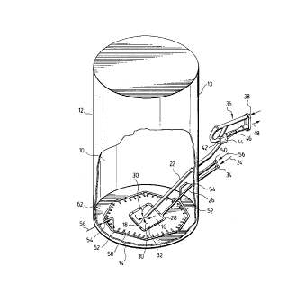
Figure 1 is a perspective view, partially cut away, of a storage tank
having; an essentially flat bottom;
Figure 2 is a cross-sectional view of a storage tank having a converging
sloped bottom and
Figure 3 is a perspective, cut away view of the storage tank of Figure 2.
DETAILED DESCRIPTION OF THE PREFERRED EMBODIMENTS
The present invention deals generally with the process of removing
hydrocarbons and salts from oily sands such as those typically found in heavy
oil sands of Alberta, Canada. The oily sand goes through a series of treatment
steps until it is eventually separated into its slop oil emulsion, water and
solid
materials fractions. Either in the field or during processing steps, solid
materials settle and accumulate on the bottom of the tank and limit the
effective
volume of the tank for storage of oil to be treated or production sands.
Traditionally, it has been necessary to remove the fluids from the tank and
physically get in and shovel out the settled material. Thus the tank could not
be
used in a continuous manner to achieve storage of an optimal amount of oil. By
removing the solid material in a manner which is commercially practicable,
increased cost efficiency can be achieved. Once the settled material is
removed,
additional volumes can be processed. The current invention solves the problem
of removing settled material from the bottom of tanks without agitating the
oil
and water layers and provides a method wherein it is not necessary to shut
down the operation to clean the tanks. This invention may be applied to
primary
storage tanks used in the field or to other sequential processing tanks that
accumulate solid material. Although the invention is illustrated with respect
to
the oil industry, aspects of the invention may be applicable to any situation
CA 02230306 1998-02-23
4
where it is desirable to remove settled materials without disturbing an
overlying
fluid layer.
In one aspect of the invention, an apparatus for removal of settled
material from flat-bottomed circular tanks and a method for its use are
provided. In a preferred embodiment, a tank desanding system is applied to a
circul<~r tank having a capacity size of less than 1500 barrels. Referring to
Figure 1, settled material 10 accumulates at the bottom of the tank 12. The
tank
12 has. upright walls 13 and a flat circular bottom 14. The method of
desanding
generally involves applying low velocity water to the settled material such
that
it becomes suspended and is thereby evacuated without excessively or
appreciably disturbing the upper fluid layers. Once suspended, the central
portion 16 of the settled material 10 is evacuated into a suction port 18 and
aspirated through a suction manifold 22. The supplied water 24 is typically
low
pressure and high volume. The water 24 enters the tank via an inlet pipe 26. A
valve 34 controls the on/off, pressure and volume of water being supplied.
Typically, the minimum flow rate and pressure shall be 100 US gallons per
minute and 125 psi, respectively. The flow rate and pressure and are
sufficient
to suspend and stir up the settled material particles, but not disturb
appreciably
the upper liquid layers.
In a preferred embodiment there is a center manifold 28 which may be
generally rectangular in shape and outer manifolds 52 which form a
substantially circular pattern around the perimeter of the tank. However, it
is
understood that the shape and configuration of the manifolds may vary. The
water from inlet pipe 26 supplies a center manifold 28 which has a series of
discharge nozzles 32 which are directed generally upwards and through which
the water enters the tank. The input water flowing into the settled material
16
via the discharge nozzles 32 causes the sand particles to become dispersed
within the water. This sand and water suspension is then aspirated in the
direction of arrows 30 from the tank via the suction port 18 and the suction
CA 02230306 1998-02-23
manifold 22. Negative pressure within the suction manifold may be provided by
various means such as, for example, rotary or reciprocating pumps, a sliding
vane pump, a rotary piston pump, a rotary compressor, a diffusion pump or an
ejector type device. In a preferred embodiment, a jet pump 36 is provided.
5 Motive water 38 enters the jet pump 36 and is propelled through the jet
nozzle
42 to form a jet stream within. the enclosure 44. The jet pump 36 is in
communication with the suction manifold 22 to evacuate the sand and water
suspension from the tank 12. The sand and water emulsion is propelled though
a mixing chamber 46 and the sand is dispelled from the jet pump in the
direction of arrow 48. This process continues until the settled material is
removed from the center of the tank. The length of time required to remove the
central settled material is proportionate to the depth of accumulated
material.
For example, it typically takes at least 15 minutes to remove centrally
settled
material that has a depth of three feet.
Once the material has been removed from the center of the tank, the
water supply 24 to the center manifold 28 is typically shut off and water 56
is
supplied to the outer manifolds 52 via inlet pipes 54. However, there may be
situations where it is desirable to supply water to all the manifolds at the
same
time. A valve 50 controls the pressure and volume of the supplied water 56.
The outer manifolds 52 are provided with discharge nozzles 58 that are
directed
generally towards the center of the tank. As with the center manifold 28, the
water is supplied at a minimum velocity of about 100 US gallons per minute
and about 125 psi, although these parameters may vary. The purpose of the
outer manifolds 52 is to facilitate the removal of material that has settled
around the perimeter 62 of the tank 12. As the water is discharged through the
nozzles 58, the settled material is suspended and simultaneously pushed
towards the center where it is evacuated through the suction port as
previously
described. The amount of time required to remove the settled material from the
perimeaer of the tank is once again proportionate to the depth of accumulated
CA 02230306 1998-02-23
6
solids. It typically takes about 15 minutes to remove three feet of settled
material which greatly reduces tank treatment compared to the prior art.
An important aspect of this invention is that the process is able to
remove the settled material without appreciably or excessively disturbing the
water and oil layers on top. This is accomplished through the suspension of
settled material particles in water, followed by evacuation of the slurry from
the
tank. Several parameters including the configuration of the manifolds as well
as the velocity of the water and the rate of evacuation are selected to ensure
that
1 ) the material is adequately suspended for suction without being propelled
at a
velocity so great that the particles will disrupt the water and/or oil
surface, 2)
material is removed in a multi-stage sequential manner that is least likely to
be
disruptive (i.e. the center portion is evacuated initially followed by the
perimeter) and 3) the suction is applied at a rate sufficient to effectively
evacuate the solid material without applying undue negative forces on the
water
and oil layers. Because it is not necessary to empty the tank for desanding,
additional material can be processed. In addition, because it is not necessary
to
assign employees the task of entering the tank and removing the solid
material,
this invention affords safety and timeline advantages and provides for a more
efficient utilization of equipment and manpower. In accordance with this
invention, the system may be operated on an intermittent manner to remove
solids without having shut down tank operation. In the usual manner, the oil
layer and slop oil may be removed from the tank top.
In another aspect of the invention, an apparatus and process for the
removal of settled material 10 from tanks having a capacity of about 1500 to
about 2000 barrels is provided. Referring to Figure 2, the tank 12 has upright
sides 14 and a converging sloped bottom 16. A suction device for removal of
the solid material is also provided. As stated above, the suction can be
furnished by a variety of devices, however, this type of tank is more suited
to
an ejector device. In a preferred embodiment, a jet pump generally indicated
at
CA 02230306 1998-02-23
7
18 is internally mounted in the converging section of the base. Desanding of
these tanks generally follows three stages of suspension of the settled
material
10. The process typically involves the utilization of three manifolds, an
inner
manifold 32, an intermediate manifold 36 and an outer manifold 40. In the
primary operation, water is supplied to the inner manifold 32. Dispersal
supply
water 20 and motive water 22 are pumped into the jet pump 18. The settled
material closest to the center of the tank is suspended by water 20 exiting
the
inner manifold 32 through discharging nozzles 34. The water and sand
suspension is aspirated through a suction port 28 and is then pumped out by
the
j et pump 18 as a slurry. The length of time required to remove the settled
material at the center depends upon the depth of the accumulated material. For
example, it typically takes only a minimum of 20 minutes to remove center
accumulated material having a depth of three feet. Once the settled material
has been removed from the center of the tank, then water 20 is supplied, as
described above for the inner manifold 32, to the intermediate manifold 36 and
discharged through nozzles 3 8. This results in the simultaneous suspension
and
propulsion towards the center of settled material around the perimeter of the
intermediate portion 44 of the converging tapered bottom and through an area
of equivalent diameter. The suspended material is then aspirated through the
suction port 28 and through the jet pump 18 as described above. When this
operation is complete, the water supply to the intermediate manifold is
terminated and water is supplied to the outer manifold 40, in the manner
described above for the inner 32 and intermediate 36 manifolds, and is
discharged through nozzles 42. The settled material accumulated around the
perimeter is simultaneously dispersed and propelled towards the center where
it
is aspirated into the suction port 2 8 and evacuated via the j et pump 18. The
water required for suspension is supplied through the various manifolds at
least
a minimum velocity of 120 US gallons per minute and 125 psi. The velocity
shall be sufficient to suspend and stir up the particles adequately for their
CA 02230306 1998-02-23
removal without appreciably disturbing the upper layers. The supply of water
to
the various manifolds is controlled through a series of valves as illustrated
with
respect to Figure 3. A valve 52 controls the flow of water to the inner
manifold
32, another valve 54 controls the flow to the intermediate manifold 36 and an
additional valve 56 controls the flow to the outer manifold 40. It is clearly
apparent to one skilled in the art that the number and configuration of
manifolds may vary and that each manifold is provided with a control valve. In
a preferred embodiment, the valves 52, 54 and 56 are solenoid controlled
valves. The valves 52, 54 and 56 are in communication, via suitable electric
wiring or remote control means for example, with a process controller which is
programmed to open and shut the valves to provide for the sequential operation
of the manifolds.
While it is typical that water is supplied to one manifold at a time
beginning with the inner manifold 32, it is understood that water may be
supplied to more than one manifold at the same time. Additional water spray
46 is supplied through inlet tubes to gently displace the settled material at
the
apex 48 of the converging tapered bottom section 16. The length of time
required to remove the settled material is proportionate to the depth of
accumulated material. It should be apparently clear to one skilled in the art
that
these types of systems described in Figures 1 and 2 as well as being applied
in
the oil industry can be used in any situation where it is desirable to
separate
solid material from a liquid slurry. Likewise it is clear that the number and
arrangement of the discharging manifolds may vary as well as the angle of
direction of the nozzles.
Although preferred embodiments of the invention have been described
herein in detail, it will be understood by those skilled in the art that
variations
may be made thereto with departing from the spirit of the invention or the
scope
of the appended claims.