Note: Descriptions are shown in the official language in which they were submitted.
CA 02230309 1998-02-25
W O 97/08494 PCT~US96/13793
PLASMA PYROLYSIS AND VI~ICATION OF
MUNICIPAL WASTE
FIELD OF TEIE INVENTION
This invention relates to a method for an ecologically acceptable reduction
in volume of rnixed waste, such as, for eY~mple, municipal waste, and more
particularly to a method for the pyrolysis and vitrifirSItion of such waste by means
of plasma arc heating technology.
BACKGROUND OF THE INVENTION
As technology progresses and the world l)ecomes more populated, more
waste is produced each day in homes, offices and in~ tri~l plants. In the past,
waste has been AnmreA into l~nAfill~ located near most municipalities or into the
oceans, with litde regard for the physical space con~.. f-l or the potential damage
done to the en~/--.)-~...~n~ More lecenLly land space allocation and en~ n.,,~
damage have become ~.~bsl~..L;~l public concerns.
The prior art, as does the present invention, recognizes that if waste is
Ll~ls~3olL~d to a central loc~ti~n~ pyrolysis and viLIi~icaLion can be accomplished,
ili7.ing plasma arc heating te~hnclc)gy, in an efficient and safe manner and useful
gaseous and vitrified products produced so as to avoid placing the waste residue into
a l~ntlfill The invention disclosed ~lesGn~ a versatile system for the h~n~lling of
mixed waste which improves on earlier Sy~t4.1~S and which can be sized for the
~ui~ ellLs of the particular (lua~Lily of waste to be proce~e~i
As described in United States Patent 5,280,757 and other prior art noted
below, plasma arc heated processes are receiving considerable attention for waste
tre~trn~nt over fuel combustion heated processes because of several distinct
advantages of plasma heat w_ich is well suited for the pyrolysis and vitIific~tion of
waste rn:~teri~l~. A plasma arc torch operates by supporting a high voltage electric
arc on a flow of plasma (ionized) g~s to generate an extremely hot "flame". The
CA 02230309 l998-02-25
W O 97/08494 PCTAUS96/13793
-2-
quantity of plasma gas flowing through the plasma torch is significantly less than
the quantity of gas required to release the equivalent heat energy by the combustion
of hydrocarbon fuels. A further lliLr~,~ce and advantage of a plasma torch heat
source over a combustion heat source is that the plasma torch can be used to
produce useful by-product gases of higher caloric content referred to here as the
clf,g~ing process. In ~ ition~ by virtue of the fact that a plasma arc torch uses
only a small ~ua l~i~y of gas to support the arc and gf ~-c-~te the heat, combustion is
unlikely to occur spontaneously in the m~teri~l~ which are being heated. A majoradvantage of the plasma torch is that it is capable of unn~ lly high rates of heat
transfer, adding to its inherent efficiency. Also, the l~ el~lulc of 4,000 -7,000~C
generated by a plasma torch is much hotter than that gel.e.<l~cl by a combustionsource and is hot enough to melt any known m~tfri~l ~imnlt~nf,ously with the
pyrolysis degassing process.
An a~?al~lus and method utili7in~ plasma arc heating for proces~ing
househol~l and in~ waste in a plasma heated reactor is disclosed in United
States Patent No. 3,779,182 to the present inventor. The '182 patent is also noted
for tf~ aching the introcll~ct~ of oxygen or air to the reactor. The tf ~chings of the
'182 patent are incorporated herein by n,r~.~ce.
The term "reactor" as used herein refers to the process Co.,~i.,...f..~ vessel,
or furnace, into which refuse, e.g. mnnicir~l solid waste, is placed and heat is added
for the purpose of ~lulnû~ g the simnlt~neous pyrolysis of organics and vitrific~tinn
of inorganics of the mixed wastes.
United States Patent 5,143,000 to the present inventor cles~rihes a plasma arc
heated furnace for the treatm~nt of solid waste. Of interest to the present invention
is the fact that the '000 patent teaches loading of non-co. . ~ ed refuse through the
top of a reactor. United States Patent 5,280,757 to Carter et al. teaches a process
for treating solid waste which includes feeding, co~ ,s~ g and forcing a stream
of solid waste into the bottom of a reactor vessel heated with a plasma torch. The
CA 02230309 1998-02-25
W O 97/08494 PCT~US96/13793
'757 patent also refers to injecting st~ea-m-- into the reactor. It has not been known,
however, to provide a system in which a bulk supply of mllnicir~l solid waste iscomr~cte~ into a snbst~nti~lly air-free el~ng~t~l stream of s~ hs~nti~lly unirc,~
cross section which is posifionerl above the top of the reactor and is discl~ ,~l in
S incre.,lellL~ as co~ ,ssed blocks of waste into the top of the reactor. The present
invention thus seeks to provide such a system.
Entrapped air, if ~....iLI~;d to enter the reactor with the solid waste, will
allow combustion in an uncontrolled process and cause the rs,snlt~nt gases to be both
dirrt;l~ L in nature and non-useful as colllp~ed to those resulting from pyrolysis of
the organic waste m~ter~ alone in a subst~nti:~lly air-free environm~-nt Throughpyrolysis of organic waste, the by-product gases are principally conl~ollellls of
valuable fuels such as hydrogen and carbon mnnoxide. The inclusion of a large
4u~lLily of air will add a signifi~nt 41la-lliLy of nitrogen that will dilute the energy
cont~nt of the gas. The present invention recognizes that the ~t1mi~it)n of a limited
and controlled amount of air can be used to advantage, in conjunction with dropping
ulcl~,.llwlL~ of comp~cted waste of known size into the top of the reactor.
It is LI1~1Gr~ an overall object of this invention to provide an improved
process for plasma pyrolysis and vitrific~*on, which reduces the volume of inputmixed waste m~t~-.ri~l~, and results in by-product gases which have high energy
content that can be used.
It is a further object of this invention to provide an irnproved waste feeding
system for use with the pyrolysis and vitrific~tion of mixed waste.
It is an ~d<li*on~l object of this invention to provide a system which
"
pyrolyzes the o,~al~ics of mixed waste in~ ding the wastes' moisture content and2~ vitrifies the inorganics of mixed waste effici~ntly based on using an improved waste
feeding system in conjunction with introducing confrolled ~mo~lnt~ of air and
recycling the steam derived from the moisture content of the mixed wastes.
CA 02230309 1998-02-25
W O 97/08494 PCT~US96/13793
Other objects and advantages will be more fully a~palcnt from the following
closnre and appended claims.
SUMMARY OF THE INVENTION
The system disclosed herein u~ ves upon the type plasma arc powered
S reactor disclosed in the earlier patents notcd. Mixed waste, such as municipal waste,
is brought to the reactor site and placed into a supply bin. A colll~lessillg conveyor
compacts and transports the waste from the bin toward the top portion of the reactor
where a selçct~(l part of the co...l ~Led waste is dropped into the reactor when it is
ti~h,,..i~ that the height of waste within the reactor is lower than desired.
Through compaction of the waste prior to placing it into the reactor, the volume of
the waste and the amount of air clltlapped in the waste are ~ignifi~ntly re~ ce~1,
leading to an improved by-product gas composition. A plasma arc torch is pivotably
suspended from an angled top plate of the reactor so that the torch resides
perpendicular to the top plate when in its central angular position. Inlet tubesintroduce a limited and controlled amount of air or other oxygen-co.)~ i.. g gas to
perrnit a controlled combustion in the reactor, thus re~illcing the energy required of
the plasma torch. The rising hot fuel-laden gas preheats the down-flowing wastesand converts the wastes' moisture into steam. The steam is collected and is forced
into the pyrolysis/vitrifir~tion zone, the int~rf~e of the plasma flame and the
vitrified inorganics. The molten glass and m~ s are tapped for recycling. The
gases produced are ch~nnelt~l through a collection m~nifokl to a scrubber/scp~tosystem.
BRIEF DESCRIPTION OF THE DRAVVINGS "
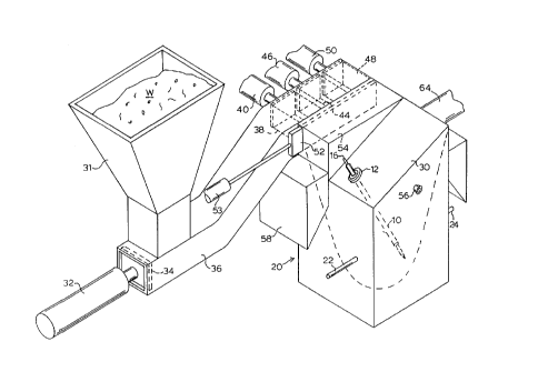
Pigure 1 is a L,~ e view of the system of the invention with waste
c~ mp~cting and top loading delivery ~ LuS connected to the reactor, the hearth
being outlined and portions of the delivery a~a~us being shown in dashed lines.
CA 02230309 1998-02-25
W O 97/08494 PCT~US96/13793
S
Figure 2 is a front elevation view of the reactor of Figure 1 with the hearth
outlined and the torch being shown in various positil-n.c in dashed lines.
Figure 3 is a cross section~l view of the reac~or of Figure 1 taken in the
direction of line 3-3 of Figure 2 and showing a Uock of comr~cte~ mixed waste
m~teri~l being dropped into the body of the reactor.
Figure 4 is a top plan view of the reactor of Figure 1 with portions of the
torch and of the waste delivery ap~al~lus being shown in dashed lines.
Figure ~ is a cross secti~ n~l view of the reactor of Figure 1 as taken in the
direction of line S - S of Figure 2.
DETAILED DESCRIPTION OF THE INVENTION
Accortlin~ to the objects of the invention described above, the reactor
employed in the plasma pyrolysis and vitrific~tion system is ilhl~tr~qte~ in Figures
1 - 5. A reactor housing 20 is cons~ t~l of l'~,lld~ ,'ly brick and is preferably
formed subs~nti~lly rectangular in ~Ytt~rior shape, with an interior configuration
tapering inward to l)ecolllc na,~ toward a hearth 26 at the lowest interior portion
of the structure. Hearth 26 is in the form of a bowl and is adapted to receive molten
waste m~ter~ which exit from hearth 26 through a tap 28. A ~lcrell~ m~tf~ri~l
for the refractory brick is ~1,..~,;,.l.." oxide which exhibits high heat tolerance and
~cçll~nt therm~l insulative ~-~s.
The top of reactor 20 above the hearth 26 is Idivided into two sections.
r~ Angular top panel 30 covers a first portion of reactor 20. Plasma arc torch 10
(Figure 1) is mounted by means of a pivo~ally movable srhçric~1 mounting 12 to
angular top panel 30. In its ~ng~ rly cent-ral position, labeled 10" in Figure 2, torch
10 resides ~loxim~ely perpendicular to angular top panel 30. Thus, the angle of
2~ top panel 30 below hori7.c)nt~1 is (l~pçnrl~nt on the height and width of reactor 20.
CA 02230309 l99X-02-25
W O 97/08494 PCTAJS96/13793
--6-
In the ~rerwlcd embodiment, an acute angle "a" (Figure 2) is be~ about 15~ -
25~. When pivoted, torch 10 may be moved from position 10' to position
lO"'(shown in dashed lines in Figure 2) to direct its generated heat at various
locations on hearth 26. The position of torch 10, labeled 10' in Figure 2, is
provided to permit the concentration of torch heat at tap 28 so as to allow melted
waste to flow out from reactor 20. In coordination with its pivotability, torch 10 is
rlrt~ ihlethrough sphericA~ nl;,~g 12 so as to ll.Ail~ acon~i~tlont~ t~n~e
bcl~..e~ the discharge end of torch 10 and hearth 26, see Figure 2. The relationbetween the amount of torch 10 çxt~.n~ion and its pivot angle is controlled by means
of a mi~;.oplocessor, not shown. Plasma arc torch 10 is generally supplied with
electric power, cooling fluid and plasma gas through supply conduit 16 from
a~l~-iate sources, not shown. The power rating of torch 10, the ca~acity of the
waste conveying and comr~cting ~p~alus and the size of the reactor 20 are all
variable according to the type and volume of waste to be proce~se~ by the specific
system. It is ~lGrGll~d to operate plasma torch 10 in the non-~ Ç~eci mode with
reversed polarity, i.e. with the int.orn~l t~rmin~l being positive. ~nri7Ont~1 top panel
54 (Figure 1) covers the second portion of reactor 20. A gas stack 64 (Figures 2and 4~ connects the interior to the ~Ytto.ri~r of reactor 20 and then directs by-product
gases to a sllit~ble gas collection or proce~sing system.
The delivery system of the invention is believed to be particularly unique.
In this system, mixed waste W is supplied to a bin 31 from which it is moved under
pressure by ram 34 which is driven linearly by hydraulic cylinder 32. The
composition of the e~ ed air bel~ and within pieces of compaçte~ mixed
waste typically inclll(les approxim~t~ly 75% nitrogen. Nitrogen is an undesirable gas
col--~o-.elll in the process of the invention since it is not useful to produce the fuel
end products contempl~tefl, for eY~mple, hydrogen and carbon monoxide. As waste
W is moved from bin 31 through supply chute 36 it becomes comp~ct~ and
increased in density and is also elevated such that the compaçted waste travels over
the top of the reactor for discharge. These changes çlimin~te the major portion of
air entrapped within and b~lweell pieces of raw, uncompacted waste. In addition,
CA 02230309 1998-02-25
W O 97/08494 PCT~US96/13793
--7-
cr,mr~ctirn of the waste W acts to seal supply chute 36 so as to pl~v~ t outside air
from ent~orin~ the reactor system, which is otherwise sealed against atmospheric air
inf~tration. The compaction performed according to the ~ ciÇ~ ,d embodiment alsobeneficially reduces the volume of waste W from about 75 to about 40 cubic feet
per ton or less, thus increasing the mass per hour of waste which can be treated in
a reactor of a particular size. Although the concept of comr~ctin~ solid waste to be
processed in a plasma arc heated furnace has been contçmrl~teA before, the present
invention provides a unique cnmhin~tion of comp~c~ing waste and delivering
selected segmrnt~ of the comracte(1 waste into the top of the reactor 20 rather than
into the bottom of the furnace and ~ ly into the melt as in the prior art.
As waste W is moved through chute 36 by the comr~cting forces of cylinder
32, waste W is also moved into a waste inlet position to enable the controlled
introduction of individually comracte~ seg.~-r~-L~ of waste into the top of reactor 20
in coor~lin~tion with keeping the waste within the reactor at the same predetr . . . Ii,~rA
level. As shown in Figure 1, highly co. . ~ t~l waste segmt-nt.~ 38, 44, 48 at a first
location in a continuous stream of co.~ a. l~cl waste W are sequentially positioned
~(ljacçnt waste ll~-~Olt~ 40, 46 and 50 in the form of delivery cylinders. Whileit has been previously known to ..~ the level of the waste being processed in
a reactor, the ability to keep waste W re~on~bly level within reactor 20 in
coo.~ ion with introducing comr~cte1 portions of waste adds to the overall
effls~i~ncy and efC;icliveness of proce~ing, accol~ g to the invention. Height
cl~e ~ g sensor 56 (Figures 3 and 4) is provided to ~Irl~ c the height of waste
W in reactor 20. Height sensor 56, in co..,~ n with a controller (not shown)
acts to tleh ..~ e whether the waste W is below a desired height. Sensor 56 can be
of the form of a light source and ~holost,llsiliv-e cell, a tPlevision carnera, or another
type of device ada~t~d to detect the presence of an object.
Sliding gate 52 is moved laterally by gate cylinder 53 to expose one or more
of blocks 48, 44, 38, in s~u.,nce. While such blocks are illustrated in Figures 1 and
3 as having relatively smooth sllrf~ces, such nlrf~res in praC*ce assume a
CA 02230309 1998-02-25
W O 97/08494 PCT~US96/13793
--8--
nifi~ntly rough texture. A signal indicative of the height i~lro~ a~ion is
ecl to respective delivery cylinders 40, 46 and 50, one or more of which are
activated in coor~in~tion with sliding gate 52 to push a block of waste 38 (Figure
3) into reactor 20 at a second location below top panel 54. C'~ cl;on cylinder 32
is connectecl to the same controller as are waste delivery cylinders 40, 46 and 50 and
gate cylinder 53 so that the various cylinder ~y~ms operate in coordination to avoid
possible i~ lr~,lellce, all of which will be a~,n~ to those skilled in the art.
TmmP~ t~ly after each comriqct~l waste block 38 is discharged from chute 36 in
c~-mracte~ condition, the waste in the block rapidly expands to a loose block 38'
and nltim~tely returns to a~Loxi.. ~ely its original volume of 75 cubic feet per ton
as waste mass 38". It should be appreciated that because of the prior compactionof the waste, the amount of air and water introduced into the reactor by the waste
is minim~l
The amount of water co.~ 1 in waste W varies according to the waste
composition and other factors. The process of co.nl~a~-l;.. g waste W as well as the
pre-heating of incoming solid waste m~teri~l within the reactor which n~t~ lly
occurs by rising heat flow comrletely removes subst~n~i~lly all en~ ed moisture
in the waste. The pre-heating of incoming waste by rising heat benefits the process
.cignific~ntly because less heat energy is then required to effect pyrolysis andvitrifit~tion. A controlled amount of water, typically in the form of recycled steam
removed from the waste or supplem~nt~l steam, is injected when desired through
one or more steam inlet pipes 24 to follow the process depicted in the formula
below. A plurality of steam inlet pipes 24, preferably one pipe 24 per 60~ around
the cil~ ,l,ce of reactor 20, are provided though not shown for purposes of
simplifying the illustration. In most cases, the recycled moisture content of the
waste feed is adequate for promoting the complete pyrolysis of the waste organics.
A large proportion of the chemi~l composition of n~ixed waste comrri~es
carbon, hydrogen and oxygen. Other components of the mixed waste are inorganic,
and are not direc'dy reactive. A typical sample of mnniciral solid waste would
-
CA 02230309 1998-02-25
W O 97/08494 PCTAUS96/13793
g
contain the following: C30 H:48 ~19 NQS SOO5. The expected yield from cllel-~ical
reactions in~uc~l by heating the mixed mnnicir~l waste and steam is depicted by
the formula:
C~Hy + H20 -> CO ~ CO2 ~ H2
S where C~Hy l~ ,s_nl~ an ~W~ y carbohydrate and the H20 coll~ollent in(1ic~t~s
~e recycled steam. The hydrogen and carbon monoxiAe are useful fuel-gas by-
products. Reduction of the quantity of nitrogen, such as by reducing inch~le~l air
by means of compaction, improves the makeup of the by-product gases as seen
below. A typical comr~r~tive chemical analysis of a gas produced from pyrolyzed
mixed waste introduced into the reactor in an unco.~ cl~l or a comracte.d con~lition
yields a notable dirr~ ellce, as the chart of gas volume test results shows below:
Ch~m;~a1 UncomPacted Waste Compacted Waste
H2 41% 47%
CO 30 35
N2 16 7
CO2 8 6
Trace gas of 5 5
complex hydro-carbons
It will be noted that the reduction in the p~,n;~ ~ge of nitrogen achieved due
to comp~ion results in an in;,~,asc in the ~E~ce.,~ge of hydrogen and carbon
monoxide, which are desired products needed in the manufacture of such fuels as
meth~nol or CH30H.
A further efflcien~y has been accompli~h~l by the invention disclosed by
adding a small amount of air or other oxygen-cc.i-~A;.-i..g gas to t_e reactor at a
loc~tion above but pro~cim~t~ the flame of the plasma arc torch via an air inlet pipe
22, thus allowing a controlled combustion of waste org;anics to occur. It has been
discovered that this controlled combustion contributes heat gellt;laLion and reduces
~e amount of energy cnn~um~l by the operation of plasma torch 10. By
introducing the blocks of compacted solid waste into reactor 20 from above and into
the upper portion of the reactor, a level of waste is m~intz-in~l above the flame end
of plasma torch 10. Thus, the heat from torch 10 and additional heat generated by
-
CA 02230309 1998-02-25
WO 97/08494 PCTAUS96/13793
-10-
the controlled combustion will rise through the waste to pre-heat the ..lcolliulg waste
m~tPri~l The heat added by cc mhll~*on is useful mainly to reduce the amount of
torch- gPnP~r~te~ heat needed to pyrolyze and vitrify the waste m~tPri~l In
particular, the energy con~u",~Lion of a 150 kilowatt (kw) plasma arc torch has been
r~lluced from a~prox;~ ely 580 kw to al)pl~x~ ely 530 kw or less per ton of
waste by the ~ li*on of 12 cubic feet of air to the reactor per ton of waste treated.
It is recognized that an ~ltern~te m~thocl of promnt*ng the desired combus*on within
reactor 20 is to supply plasma arc torch 10 with a plasma gas having an enn~hPA
oxygen component. Greater qu~nt*t*es of an oxygen-con~ gas, however, have
been fiel~.l .. i.~P~ to not yield l,l~clLional increases in input power-to-heat efflciency
of the system.
As noted above, a major portion of the output from the process of the
invention is in the form of gas, the balance being molten waste m~t.ori~l which cools
to a vitrified mass. The gases produced have a high energy value co..~ i.-g of
sçncible heat energy due to their high t~ .. p~ and c~lorific heat energy from the
hydrogen and carbon monoxi-le The hot product gases are rYh~net~Pd from reactor
20 through manifold 58 generally disposed around the periphery of reactor 20, and
stack 64 (Figures 2, 3 and 4). As the g~le.alt;d gas passes through vents 57 into
manifold 58, it is forced through pipe 62 so as to transverse barrier 60 through a
water bath fed by water supply 68. A pH sensor (not shown) ~nPr~t~s a signal to
activate pH adjustor 66 (Figure 2) when l~uil~,d according to established levels,
which serves to add lime and ~ ,asG pH. After the water bath, the gas flows
through duct 64 to a scl.lbl~./~ .. 70 and then to a turbine generator (not
shown) to gen~ ehP~ ty. The -PlPctricity produced is useful to feed plasma
torch 10 or for other ~ oses. The molten waste may contain various amounts of
silic~tes, r~-lio?lctive Pl~p~mpnt~ heavy metals, etc, which are effectively rendered safe
by vitrific~tion which encapsulates and immobilizes heavy metal co~ o~ s and
r~-lionllcli~P,~,
CA 02230309 1998-02-25
W O 97/08494 PCT~US96/13793
After the exh~ t gas ~ lw~, has passed throl~gh the turbine g~i~f.~all~r, it
will have lost its s~-nsihle heat. The cooler hydrogen and carbon mono~i(lç gas is
combusted to produce ~lAition~l PlF~tricity
The heat energy recovery consists of (1) the s.o.n~ihle heat from the plasma
S heater, and (2) the c~lonfic heat from the hydrogen and carbon mon~xi(1e generated
by pyrolysis of the waste organics. The sum of the s~n~ible heat and the c~lorific
heat is a~ xi,-~ y equal to the energy content of the waste organics, or about
900 KWH per ton of wastes. The plasma heat r~uirGd to effect the total recovery
of the wastes' energy is ~r~xi",~lely 500 KWH per ton of waste. Thus a net gain
in the range of 400 KWH per ton of waste is realized.
As ~lis~losed herein, the improved delivery system contributes to the plasma
pyrolysis and vitrific~tion system of the invention and provides an effective means
for neutralizing the hazardous components and re~ncing the volume of mixed
mnniciral waste products while achieving a positive energy prodllction.
While the invention has been ~Içs~ril-ecl with lGr~llce to specific
embo~ F --L~ thereof, it will be a~,~ia~d that nulllGrous v~ri~tion~, morlific~tions,
and embo-limlont~ are possible, and accordingly, all such v~ri~tion~ modifications,
and embo~ are to be regarded as being wi~in ~he spirit and scope of the
invention as set forth in the claims which follow.
INDUSTRIAL APPLICABILlTY
The invention ~li~.losed herein is particularly in~ tri~lly applicahle This
invention provides in~hl~trial u~Ollul~ily for the m~nllfactllre of the reactor and
waste h~n~lling and com~acLh~g a~p~alus ~ closed This invention further providesin~ tri~l opp~lLulLily in the process which is taught for the pyrolysis and
vitri~cation of mnniciral waste. Finally, this invention provi~es indnstri~l
Opl)Ollul~ily in ~at as a by product of the process taught, gas is collected and
CA 02230309 l99X-02-25
W O 97/08494 PCTrUS96/13793
transformed into fuel m~t~ri~l~ which will be ~ubseluenLly used to g~ ~f~
electricity. Thus, the invention serves the environment by redllf~-ing the impact of
solid waste and further by recovering the energy trapped in such waste and stillfurther by ge-lf ~aLulg l~,laLi~vly clean electric power.
S PREF~RRED EMBODIMENT
Apparatus for the pyrolysis and vitrifif,ation of mixed waste, comrri~ing a
reactor providing a waste proces~ing chamger with a hearth a the bottom of the
chamber and above said hearth an enclosing structure having side walls and an atleast partially angularly f rif.ntecl top panel, means for delivering the mixes waste to
the reactor, comrri~ing a storage r~Lacle for receiving a bulk supply of mixed
waste, a compactor ~oci~t~cl with the receptacle to receive and compact ~uçces~ive
4u~lLiLies of the mixed waste with ...;..i...--... entry of air and Llansrer the mixed
waste as an çl~ ng~teA compacted mass of :".h5~ 11y uu~irvlln cross section to afirst location pro~im~t~ the top panel, a waste inlet at a second loc~tion ~r~x;...~
the first location for receiving cf mr~cted waste to be proce~ed within the reactor,
the waste inlet being configured for receiving ulPirulll.ly sized sçlected portions of
the compacted waste removed from the elongated comractçd mass and a transporter
operable in coor~ aLion with the fol.l.i.lt of the elong~t~A com~cted mass of waste
at the first loc~tion for moving the sel~l~ portions of the comracteci el~ ng~t~d
mass through the waste inlet into the chamber, and a pivotally mounted elong~teAplasma arc torch mounted in the ch~mher and providing a source of pl~cem~ heat
at a discharge end thereof directed toward the hearth for the pyrolysis and
vitrification of the waste m~ter~ wl-~v~elhl the a~alaLuS further comrri~es means
for ~-lmitting controlled amounts of air, means for ~-lmitting controlled amounts of
steam, a sensor for m~mring the level of waste in the cl~ .be. and coorflin~tingthe ~-lmi.~ion of cc mracttoA waste lller~ ll, a p~ hf . ;~lly disposed outlet for the
removal of gas produced during pyrolysis from the a~al~us.