Language selection

Search

Patent 2230400 Summary

Third-party information liability

Some of the information on this Web page has been provided by external sources. The Government of Canada is not responsible for the accuracy, reliability or currency of the information supplied by external sources. Users wishing to rely upon this information should consult directly with the source of the information. Content provided by external sources is not subject to official languages, privacy and accessibility requirements.

Claims and Abstract availability

Any discrepancies in the text and image of the Claims and Abstract are due to differing posting times. Text of the Claims and Abstract are posted:

  • At the time the application is open to public inspection;
  • At the time of issue of the patent (grant).
(12) Patent Application: (11) CA 2230400
(54) English Title: ELECTRONIC SENSOR FOR VARIOUS APPLICATIONS INCLUDING GOLF BALL SERVING MACHINES
(54) French Title: DETECTEUR ELECTRONIQUE POUR DIFFERENTES APPLICATIONS, ENTRE AUTRES LES SERVEURS DE BALLES DE GOLF
Status: Dead
Bibliographic Data
Abstracts

English Abstract


In a machine which automatically serves golf balls on a tee-like holder to a
practicing golfer, difficulties arise in regard to sensing that the ball has
been hit off the tee
so the machine may respond by reloading the tee with another ball.
The high-impact involved in the striking of the ball creates problems for
sensitive
or delicate weight sensors. Also moisture and dirt create malfunctions with
infra-red ball
presence sensors. In addition to reliability problems, the above sensors are
expensive.
In this invention, a flexible but durable tee with electrically conductive
elements is
surrounded by a conductive ring. When the golfer strikes the ball, the tee is
deflected
bringing the conductive elements of the tee in contact with the conductive
ring, thus
completing an electric circuit which signals the machine's processor(s) that
the ball has
been hit.
Additional applications of this invention include an off level sensor, an
acceleration
or vibration sensor, and a passing object sensor.


Claims

Note: Claims are shown in the official language in which they were submitted.


The embodiments of the invention in which an exclusive property or privilege
is
claimed are defined as follows:

Any electronic sensor consisting of a flexible shaft with conductive elements
which
passes through a conductive ring such that deflection of the central shaft
causes contact of
the shaft with the ring closing an electric circuit.

Description

Note: Descriptions are shown in the official language in which they were submitted.


CA 02230400 1998-04-30
Sgecificatiorls
The invention relates to a sensor for detecting deflection in a variety of
applications including deflection caused by striking of a ball off the
sensor's shaft in a
machine for automatically serving golf balls to a practicing golfer.
It is common in golf ball auto-teeing machines to sense the presence or
absence of
the ball by weight or light sensors. These are expensive and unreliable due to
the high
impact involved and dirt and moisture problems in this application.
This invention describes a very affordable and durable solution to sensing the
striking of a ball on a tee. In addition, this invention's sensor apparatus
can serve multiple
other applications including off level sensing, acceleration or vibration
sensing, and
passing object sensing.
In drawings which illustrate the embodiments of the invention, Figure 1 shows
the
general design of the sensor. Figure 2 shows the sensor as it applies to ball
serving
machine applications. Figure 3 shows the sensor modified for ofd level or
acceleration
sensing. Figures 4, 5, and 6 show the sensor as applied to the tasks of off
level sensing,
acceleration sensing, and passing object sensing respectively.
In Figure 1, a durable flexible shaft 1 is mounted through but not touching a
conductive ring 2. The shaft 1 is itself conductive or fitted with conductive
elements such
that when the. shaft 1 is deflected and makes contact with the ring 2, an
electric circuit
involving the shaft l and the ring 2 is momentarily completed. In this
drawing, the line
marked '3' represents a wire connected to the ring 2, and the line marked '4'
represents a


CA 02230400 1998-04-30
wire connected to the conductive elements of the shaft 1. 5 represents a power
source and
6 represents a relay or appliance activated by the momentary completion of the
circuit.
Figure 2a shows this same sensor as it would operate in a golf ball serving
machine. Figure 2b shows the same immediately after the ball 8 is struck off
the tee shaft 1
by the golf club 7. Note that the sensor shaft is deflected, closing the
sensor circuit.
In figure 3, the shaft 1 of the sensor is weighted; here this is shown by the
fixed
weight 9 fixed to the end of the sensor shaft 1. This modification allows the
sensor to
operate as an off level or acceleration sensor.
Figure 4 shows the sensor activated by the pull of gravity on the sensor shaft
weight 9, causing deflection of the sensor shaft 1 when the unit is adequately
tilted or "off
level".
Similarly figure 5 shows the sensor activated by acceleration in the direction
of the
arrow marked 10 and representing the direction of acceleration of the unit.
Note that the
sensitivity of the sensor can be modified by varying the flexibility of the
shaft 1, the mass
of the weight 9, and the clearance between the sensor shaft 1 and the
conductive ring 2.
When modified for high sensitivity, the sensor can detect fine vibration.
Figure 6 shows the sensor operating as a passing object sensor. A passing
object
11 moving in the direction of the arrow marked 12 causes deflection of the
sensor shaft 1
thus activating the sensor.
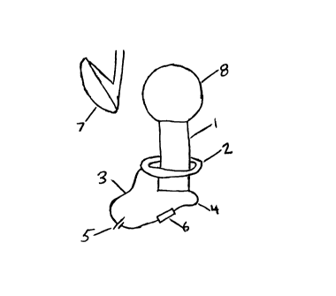
Representative Drawing
A single figure which represents the drawing illustrating the invention.
Administrative Status

For a clearer understanding of the status of the application/patent presented on this page, the site Disclaimer , as well as the definitions for Patent , Administrative Status , Maintenance Fee  and Payment History  should be consulted.

Administrative Status

Title Date
Forecasted Issue Date Unavailable
(22) Filed 1998-04-30
Examination Requested 1998-04-30
(41) Open to Public Inspection 1999-10-30
Dead Application 2003-04-30

Abandonment History

Abandonment Date Reason Reinstatement Date
2001-04-30 FAILURE TO PAY APPLICATION MAINTENANCE FEE 2001-09-13
2002-04-30 FAILURE TO PAY APPLICATION MAINTENANCE FEE
2002-06-07 R30(2) - Failure to Respond

Payment History

Fee Type Anniversary Year Due Date Amount Paid Paid Date
Request for Examination $200.00 1998-04-30
Application Fee $150.00 1998-04-30
Maintenance Fee - Application - New Act 2 2000-05-01 $50.00 2000-04-25
Reinstatement: Failure to Pay Application Maintenance Fees $200.00 2001-09-13
Maintenance Fee - Application - New Act 3 2001-04-30 $50.00 2001-09-13
Owners on Record

Note: Records showing the ownership history in alphabetical order.

Current Owners on Record
TROZZI, MARK R.
Past Owners on Record
None
Past Owners that do not appear in the "Owners on Record" listing will appear in other documentation within the application.
Documents

To view selected files, please enter reCAPTCHA code :


To view images, click a link in the Document Description column. To download the documents, select one or more checkboxes in the first column and then click the "Download Selected in PDF format (Zip Archive)" or the "Download Selected as Single PDF" button.

List of published and non-published patent-specific documents on the CPD .

If you have any difficulty accessing content, you can call the Client Service Centre at 1-866-997-1936 or send them an e-mail at CIPO Client Service Centre.


Document
Description 
Date
(yyyy-mm-dd) 
Number of pages   Size of Image (KB) 
Representative Drawing 1999-10-20 1 3
Abstract 1998-04-30 1 23
Claims 1998-04-30 1 9
Description 1998-04-30 2 69
Drawings 1998-04-30 3 25
Cover Page 1999-10-20 1 36
Assignment 1998-04-30 2 49
Correspondence 1998-05-14 1 16
Prosecution-Amendment 2001-12-07 3 103
Fees 2000-04-25 1 103
Fees 2001-09-13 1 44