Note: Descriptions are shown in the official language in which they were submitted.
CA 02230779 1998-04-03
HOROLOGICAL TIMEPIECE, IN PARTICULAR WRISTWATCH
The present invention relates to a horological timepiece, and particularly to
a wristwatch, comprising a date display device of the retrograde type.
The aim of the invention is to provide a control mechanism of this
retrograde date display device which is reliable, simple and efficient, which does
not take space in the center of the movement and which can be easely adapted to
any movement comprising a date c:rown.
The attached drawing shows schematically and by way of example one
10 embodiement of the object of the invention.
Figurls 1 is a perspective view of a wrist watch.
Figure 2 is a perspective view of the control mechanism of the retrograde
data display.
As seen on Figure 1, the wrist watch comprises a dial 1 provided with a
graduation from 1 to 31 for the date 2 cooperating with a hand 3. This hand 3 isdriven by a date mechanism so that it is displaced angularly each day of a valuecorresponding to one step of the graduation 2 and that once arrived at the 31 it is
backwardly displaced in one step, i.e. in the reverse direction of the hands of a
watch, to display the first day of the following month.
In general, in watches comprising such a retrograde date display, the
mechanism driving this display is controlled by a great lever being part of the
perpetual calendar mechanism or actuated by a gear train of the movement.
These solutions are complicated and necessitate space at the center of the
movement, center which is already very encumbered.
The rnechanism according to the invention for driving the hand 3 of the date
display is very simple and can be adapted to any horological movement
comprising a date crown.
CA 02230779 l998-04-03
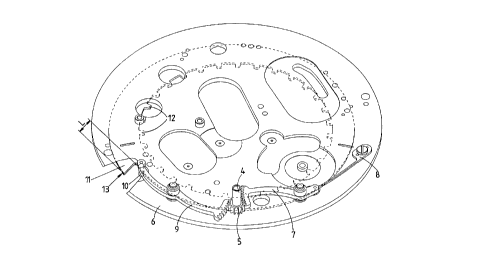
The hand 3 of the retrograde date display is carried by a sleeve 4 fastened
with a pinion 5 pivoted onto the plate 6.
This pinion 5 is meshing with the toothing of a first rack 7, pivoted on the
plate 6 and submitted to the action of a return spring 8 tending to displace thepinion 5 in the anti-clockwise direction.
This same pinion 5 is also in mesh with a second rack 9 also pivoted on
the plate 6 on the other side of the axis of the pinion 5. The free end of this
second rack 9~ comprises a feeler or roller 10 abutting against a date crown 11.This feeler lO is permanently applied against the outside peripheral edge of thedate crown 11, under the action of the spring 8 and the pinion 5. Therefore, thepinion 5, and thus the hand 3, are always positively maintained in a determinated
angular position, all the plays of the racks and pinion toothings being eliminated.
The clate crown 1 is located in the lower peripheral portion of the plate and
pivoted or guided with play by a thicker central portion of said plate 6.
The date crown 11 is maintained in height by bridges (not shown). The
driving of the date crown 11 is made by its internal toothing 12 in a conventional
and well-known manner by means of a finger or a tooth of a wheel making one
revolution each day. The angular position of the crown 11 is maintained, betweentwo successive drivings, by a jumper.
The peripheral edge 13 of the date crown 11 constitutes a helicoïdal cam
so that for each angular step of the crown 11 the feeler 10 causes an angular step
of the sleeve 4 and thus of the hand 3 corresponding to the passage from a day to
the followin(g on the graduation 2. After the 31th day of a month, the crown 11 has
made a rotation at 360~ and the feeler 10 falls of the value of the lift L of the cam
25 causing the hand 3 to come back in front of the numeral 1 of the graduation 2.
CA 02230779 1998-04-03
The modification of the duration of the months is automatically obtained by
the setting and winding stem acting on the date crown 11 as in any watches
movement comprising a rapid date crown setting.
This mechanism is very simple, it comprises only one pinion 5 and two
racks 7,9. It can be located in the periphery of the movement where one has
enough space. The data crown 11 is the element controlling the displacement of
the hand 3, this crown is well-known but for its peripheral shape which forms the
helicoïdal cam, or snail cam. All the advantages of this mechanism are due to the
fact that the drive actuating the display mechanism of the retrograde date display
10 is made by the date crown and particularly its peripheral edge.
Of course, in variants, the snail cam carried by the date crown could be
different, for example formed by a shaped groove machiened in the upper face of
the crown.