Note: Descriptions are shown in the official language in which they were submitted.
CA 02230845 1998-02-27
DOUBLE OVERHEAD CAMSHAFT ALIGNMENT TOOL
TECHNICAL FIELD
The invention relates to tools and techniques for repairing internal
combustion engines. More specifically, the invention relates to a method and
apparatus for maintaining the timing position of double overhead camshafts
during
replacement or reinstallation of a toothed, timing belt.
BACKGROUND OF THE INVENTION
Overhead camshaft internal combustion engines have almost entirely replaced
older style, overhead valve engines employing rocker arms, and connecting rods
actuated by a camshaft adjacent to the crankcase of the internal combustion
engine.
In such prior technology engines, the camshaft was typically rotationally
coupled to
the crankshaft by intermeshed sprockets. Therefore, the timing of the camshaft
with
respect to the crankshaft was relatively fixed and capable of only minor
adjustment
by relative rotation and reattachment of the camshaft with its crankshaft
engaging
sprocket.
Overhead camshafts have eclipsed the old style push rods engine primarily
due to the increased performance of the overhead camshaft engine, and
manufacturing economy. In this modern type of engine, the engine crankshaft is
journaled to a cogged, crankshaft pulley which engages a cooperatively toothed
belt.
The toothed belt also engages a cog wheel on each camshaft which drives the
same.
Periodically, the toothed belt must be replaced so that timing between the
camshaft
and the crankshaft are not lost during engine operation due to belt breakage.
In
addition, the toothed belt is often removed and reinstalled during repair or
replacement of water pumps, seals, and the like.
In a single overhead camshaft engine, such replacement is relatively
straightforward. There is generally provided a timing mark on the engine
itself
CA 02230845 1998-02-27
2
which is aligned with a corresponding timing mark on the camshaft cog wheel. A
si milar set of marks are typically provided for the crankshaft cog wheel as
well.
Rotating the crankshaft cog wheel to the correct timing position is relatively
easy
as the forces tending to rotate the crankshaft to any given position are
relatively
minor. However, depending on the strength of the valve springs which bias the
overhead valves to a closed position, and the aggressiveness of the care
surfaces,
the camshaft cog wheel is biased to a plurality of rest positions which
typically do
not cooperatively align the camshaft cog wheel timing mark with its attendant
mark
on the engine housing at top dead center, number one cylinder. Nevertheless,
an
automobile technician can relatively easily hold the camshaft cog wheel in
place
with one hand, while using the free hand to place the belt on the camshaft cog
wheel, and the crankshaft cog wheel.
The repair procedure described above becomes somewhat more difficult in
a double overhead camshaft engine. For example, in the conventional in-line,
four
cylinder double overhead camshaft engine 10 shown in Figure 1, two adjacent
camshaft cog wheels 12, 14 must be maintained in the appropriate timing
position,
top dead center cylinder number one position while the timing belt 16 is
replaced.
In an engine employing a single exhaust and intake valve per cylinder, a
technician
can generally, if somewhat difficultly maintain both camshaft cog wheels in
their
appropriately timed position with the fingers of one hand, while the other
hand
replaces the belt. However, the difficulty of this task increases dramatically
in an
engine employing four valves (i.e., two intake and two exhaust) per cylinder,
with
aggressive cam surfaces and valve return springs having large spring constants
as
is typical of today's, high performance four cylinder engines. In fact) it is
virtually
impossible for a technician of ordinary strength to hold both camshaft cog
wheels
12, 14 in place with one hand, while the free hand is used to replace the
timing belt
16. Thus, two technicians are often necessary to effect such a timing belt
replacement.
At least one automobile manufacturer has addressed this problem by
modifying tfre forward camshaft bearing saddle 18 as shown in Figure 2 of the
internal combustion engine 10. In contrast to the more rearwardly displaced
camshaft bearing saddles 20, the forward saddles are provided with projections
22
CA 02230845 1998-02-27
3
having bores therethrough which cooperate with radial bores (not shown) in the
camshafts 24. Individual, pin-like alignment tools 26 can be inserted through
the
bores in their projections 22 and the camshafts 24 to hold the cog wheels 12,
14 in
their respective, timed positions. Unfortunately, due to the very large spring
S constants of the overhead valve springs, the aggressive surfaces of the cams
28, and
the loose tolerances of the tools 26 with respect to the bores, it is possible
for a
technician to misalign the cog wheels 12, 14 with respect to one another by at
least
a single tooth, or cog, during the belt replacement procedure. Such a result
is
highly undesirable. Therefore, a need exists for a camshaft alignment tool and
method for maintaining the timing positioning of adjacent cog wheels on
internal
combustion engines employing cog wheel equipped double overhead camshafts
during replacement of the timing belt.
SUMMARY OF THE INVENTION
It is therefore an object of the present invention to provide a camshaft
alignment tool for maintaining the timing positioning of adjacent cog wheels
on
internal combustion engines employing cog wheel equipped double overhead
camshafts driven by a cooperatively toothed timing belt during replacement of
the
belt.
It is a further object of the invention to achieve the above object by
employing a method for replacing a timing belt on an internal combustion
engine
employing cog wheels of the type described above by directly and
simultaneously
fixing the cog wheels to one another while the belt is replaced with a single
fixation
tool.
These objects, and other objects and advantages of the invention which will
become apparent from the description which follows, are achieved by providing
a
camshaft alignment tool having a main body defining a reference plane. At
least
three cog engaging members project transversely from the reference plane and
are
spaced apart relative to one another so that at least two of the projections
can
positively engage two pairs of cogs in one of the cog wheels, and so that the
remaining projection can engage a pair of cogs on the remaining cog wheels
whereby relative positioning of the cog wheel is maintained against torque
induced
CA 02230845 1998-02-27
4
on the camshaft by the valve springs during replacement of the timing belt.
The
tool is applied to the cog wheels before the timing belt is removed, and is
removed
from the cog wheel after the timing belt has been replaced. A single
technician can
perform this operation without assistance.
In the preferred embodiment of the invention, four projections are used. The
projections are arranged in two pairs with the first pair positioned for
engagement
of a first cog wheel, and a second pair positioned for engagement of a second
cog
wheel. The spacing and positioning of the projections are selected
appropriately for
the mechanical dimensions of different sized cog wheels and engines.
BRIEF DESCRIPTION OF THE DRAWINGS
Figure 1 is an isometric, environmental view of a modern, double overhead
camshaft engine employing two cog wheel driven camshafts and a cooperatively
toothed timing belt.
Figure 2 is a partial isometric view of a double overhead camshaft alignment
tool technique presently employed in certain automobiles.
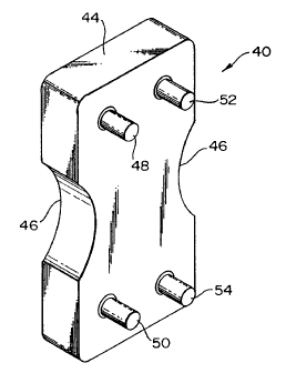
Figure 3 is an isometric, full scale view of an alignment tool of the present
invention.
Figure 4 is a schematic representation illustrating the tool shown in Figures
3-10 positioned on adjacent camshaft cog wheels of an internal combustion
engine.
Figure 5 is a front elevational view of the tool shown in Figure 3.
Figure 6 is a left side elevational view of the tool of Figure 3.
Figure 7 is a rear elevational view of the tool of Figure 3.
Figure 8 is a right side elevational view of the tool shown in Figure 3.
Figure 9 is a top plan view of the tool shown in Figure 3 as well as a mirror
image of a bottom plan view of the tool of Figure 3.
Figure 10 is an isometric, full scale view of an alternate embodiment of the
invention.
DETAILED DESCRIPTION OF THE PREFERRED EMBODIMENTS
A camshaft alignment tool, in accordance with the principles of the invention
is generally indicated at reference numeral 40 in Figures 3-9. The tool is
adapted
CA 02230845 1998-02-27
S
for use on an automobile engine 10 of the type employing double overhead
camshafts 24 journaled for rotation with cog wheels 12, 14 which are
themselves
driven by a toothed timing belt 16 in a manner well known by those or ordinary
skill in the automotive repair art.
The tool 40 has a main body 44 of generally rectangular shape having a
height of approximately 3 inches, a width of approximately 1 7/ 16 inches, and
a
depth of approximately 1/2 inch. The body is preferably made of a relatively
rigid
yet inexpensive material such as aluminum. The body may be provided with
sculpted out portions 46 which are primarily ornamental in nature, although
such
portions may provide clearance for bolts 47 used to secure the cog wheels 12,
14
on the camshaft 24. Moreover, portions 46 may also serve as an indication of
source to the relevant consuming public.
The main body 44 is preferably provided with four transverse protrusions 48,
50, 52, and 54 in the form of cylindrical steel pins having a length of
approximately
5/ 16 inch and a diameter of approximately 3/ 16 inch. Although four
projections are
shown and preferred, at least three would suffice. As best shown in Figure 4,
these
protrusions engage pairs of adjacent cogs or teeth (62, 64 for example) on
each cog
wheel such that the relative positions of the cog wheels 12, 14 are fixed
while the
tool remains installed and the timing belt 16 is replaced.
It is preferred that the relative positioning of the protrusions 48, 50, 52,
and
54 be selected so as to closely and frictionally engage adjacent pairs of
teeth on the
cog wheels 12, 14 precisely so as to avoid slipping of the cog wheels or
relative
movement of the cog wheels. To this end, and as best seen in Figure 5,
projections
48 and 50 are arranged as a first pair having a first pair separation distance
70 of
54mm, and wherein the projections 52, 54 form a second pair defining a second
pair
separation distance 72 also of 54mm. A first reference line connecting
projections
40-50 is substantially parallel to a second reference line connecting the
projections
52, 54 wherein the reference lines are substantially parallel and define a
reference
line separation distance 74 of approximately l7mm. It is also preferred for
certain
automobile brands that the first and second pairs be vertically offset as
shown in
Figure 5 by a "misalignment distance" 76 of approximately 3mm. All distances
are
measured on center of the projections 48, 50, 52 and 54 which as described
above
~
CA 02230845 1998-02-27
6
are cylindrical steel pins. The dimensions described above for the embodiment
of
Figures 3-9 are selected to closely engage the cogs or teeth, such as teeth
62, 64 of
an Accura brand 1986-1989 Integra model automobile.
To use the tool 40, the camshaft 24 should be aligned at top dead center,
cylinder number one thereby positioning the cog wheels 12, 14 in a respective
correctly timed position. The tool 40 is then applied to the cog wheels so
that
protrusions 48, 50, 52 and 54 engage cogs on the cog wheels. The timing belt
16
can then be removed and/or replaced using both hands while the cog wheels
remain
stationary. The tool 40 can also be used to maintain the relative position of
the cog
wheels while the bolts 47 are loosened or tightened thereby avoiding stressing
the
belt 16 or disturbing the relative position of the camshaft 24 which are
journaled by
keys to the cog wheels. Such operation frequently occurs during camshaft seal
replacement.
As shown in Figure 10, an alternate embodiment 40' can be provided
wherein like reference numerals refer to similar structure as for the
preferred
embodiment shown in Figures 4-9. In the alternate embodiment 40' shown in
Figure 10, the first and second pair separation distances 70, 72 are both
approximately 28mm, the reference line separation distance 74 is approximately
26mm, and the misalignment distance 76 is approximately 3mm. The dimensions
described hereinabove for the alternate embodiment 40' are selected to
positively
engage cog wheels 12, 14 of a 1988-1989 Honda brand Prelude SI model
automobile. The method of use of the alternate embodiment 40' shown in Figure
10 is identical to that described for the embodiment shown in Figures 4-9.Upon
further review and contemplation of this disclosure and the accompanying
drawings,
those of ordinary skill in the art will be able to devise other dimensional
relationships between the projections 48, 50, 52 and 54 to engage the cog
wheels
on other double overhead camshaft engines.
In addition, those of ordinary skill in the art will devise other embodiments
and variations of the invention which although not shown fall within the
spirit of this
disclosure. For example, the main body 44 need not be solid as shown but may
be
of a spider or truss configuration. Therefore, the invention is not to be
limited by
the above description, but is to be determined in scope by the claims which
follow.