Note: Descriptions are shown in the official language in which they were submitted.
CA 02230890 1998-02-27
W O 97/09010 PCTrUS96/13863
METHOD AND SYSTEM FOR DIRECT HEATING OF FLUID
SOLUTION IN A HOLLOW BODY ORGAN
R~K~-~OUl~D OF THE INVENTION
1. Field of the Invention
The present invention relates generally to the field
of thermal ablation where heat is delivered to necrose or
ablate a diseased body organ. More specifically, the
invention provides methods and devices for thermally ablating
hollow body organs, such as the uterus, by heating a thermally
conductive fluid disposed within the organ.
"Minimally invasive" surgical procedures have
recently been developed as alternatives to conventional "open"
surgery. Of particular interest to the present invention are
minimally invasive surgical procedures relating to thermal
treatment of hollow body organs, and particularly to treatment
of the uterus. A variety of such thermal treatment procedures
have been proposed which rely on a catheter to deliver heat to
the interior of hollow body organs which are filled with a
thermally conductive fluid. The heated fluid is then employed
to heat the mucosa sufficient to induce injury and necrosis of
the organ. For example, U.S. Patent Nos. 5,045,056;
5,100,388; 5,188,062; 5,222,938, and U.S. Patent Application
Serial Nos. 08/073,639 and 08/266,037, the complete
disclosures which are herein incorporated by reference,
describe catheters having a conductive heating element
disposed on the catheter which heats a thermally conductive
fluid by conventional thermal conduction to a temperature
sufficient to destroy the mucosa or endothelial lining of the
organ, resulting in deactivation of the organ.
Although workable, the use of such catheters having
conductive heating elements at their distal ends to deliver
heat within the uterus can be problematic in certain respects.
For instance, heat distribution through the thermally
conductive fluid can be non-uniform, thereby requiring an
increase in the total amount of heat delivered to the fluid in
CA 02230890 1998-02-27
W O 97/O9010 PCTrUS96/13863
order to assure that the temperature of all portions of the
mucosa are raised above the threshold level necessary to
induce injury and necrosis. However, such an increase in heat
delivery may raise the temperature of some portions of the
mucosa above a desired maximum temperature. Such excessive
heating is undesirable in that it can in some cases result in
injury to adjacent organs. As an alternative, some attempts
have been made to induce an oscillatory flow between a lumen
in the catheter and the organ in order to reduce the
temperature gradient within the fluid. Although oscillatory
mixing of the thermally conductive fluid enhances heat
delivery to remote locations within the organ, mixing by
inducing an oscillatory flow between the catheter lumen and
the organ may be undesirable in some cases because it often
creates pressure waves within the organ. Such pressure waves
may be particularly problematic within the uterus because hot
conductive fluid may be forced through the fallopian tubes and
into the abdominal cavity, thereby potentially causing damage
to adjacent organs. Oscillatory mixing is also undesirable
because of potential blockage of the catheter lumen by blood
clots or tissue particles that may be suspended in the fluid.
Another drawback to such conductive heating
catheters is the limited capacity of their conductive heating
elements to rapidly deliver necessary heat to the thermally
conductive fluid. In order to deliver sufficlent heat to
remote portions of the organ lining, it may be necessary to
raise the surface temperature of the heating element above a
desired maximum temperature. However, excessive heating can
result in fouling of the heating element as a result of
coagulation and denaturing of blood and other proteins that
may be present in the fluid, thereby reducing the heat
transfer capacity of the heating element and increasing
operating time.
Another problem experienced when attempting to
thermally ablate a hollow body organ is the existence of air
bubbles that may become trapped within the organ when
introducing the thermally conductive fluid. Air bubbles
trapped within the organ will tend to decrease the amount of
-
CA 02230890 l998-02-27
W O 97/09010 PCTrUS96/13863
heat transfer from the fluid to the endometrium. Further, in
the case of the uterus, trapped air will tend to expand when
it is heated and may cause the intrauterine fluid pressure to
increase above the desired maximum, resulting in potential
leakage through the fallopian tubes.
Hence, for these and other reasons, it would be
desirable to provide improved methods and devices which would
overcome or greatly reduce these and other problems. In
particular, it would be desirable to provide methods and
devices having improved heat transfer characteristics so that
adequate heat may rapidly be delivered to the fluid without
fouling of the heating element. The methods and devices
should also provide for a uniform heating of the fluid within
the organ, preferably without undesirably increasing the
intraorgan pressure. In one aspect, the devices will
preferably be sufficiently small to allow introduction into
the uterus through the cervical canal. Finally, the methods
and devices should allow for the thermally conductive fluid to
be introduced into the uterine cavity within a desired
pressure range and so that air bubbles do not become trapped
within the uterus.
2. Brief Description of the Backqround Art
As previously described, U.S. Patent Nos. 5,045,056;
5,100,388; 5,188,602; and 5,222,938 describe catheters having
a conductive heating element that conductively heats a
thermally conductive fluid within a hollow body organ.
U.S. Patent No. 4,676,258 describes a device for
radio fre~uency hyperthermia having a first electrode disposed
in a tract or organ and a second electrode disposed on an
outer circum~erence o~ a person to heat a tumor or malignancy
region deep inside the person.
U.S. Patent No. 5,368,591 describes a balloon
catheter having heating electrodes disposed within the
balloon.
U.S. Patent No. 5,257,977 describes a catheter ~or
introducing a heated ~luid into the urethra.
CA 02230890 1998-02-27
WO 97/09010 PCTrUS96/13863
U.S. Patent No. 5,242,390 describes a device for
introducing a heated liquid into the uterus.
U.S. Patent No. 5,195,965 describes a catheter
having a balloon for receiving a heated liquid.
U.S. Patent No. 5,159,925 describes a catheter for
laparoscopic cholecystostomy and prostate or gall bladder
oblation. The catheter includes a distensible bladder at its
distal end for receiving a heated fluid.
U.S. Patent No. 4,469,103 describes a system for
applying localized infrared electromagnetic energy to an
effected area of a body.
U.S. Patent No. 5,277,201 describes an endometrial
ablation apparatus having an electroconductive balloon at its
distal end for extending the organ and making electrical
contact with the endometrial lining to be destroyed.
U.S. Patent No. 4,430,076 describes a uterine
manipulative and injector device for uterine insertion. The
device includes an inflatable member at its insertable end
which may be inflated to seal the lower portion of the uterus
to retain fluid or gas in~ected into the uterine cavity.
U.S. Patent No. 4,375,220 describes a microwave
applicator for intracavity treatment of cancer.
U.S. Patent No. 4,979,948 describes a catheter
having a capacitative balloon electrode which may be expanded
by an electrolyte solution to conform and make contact with
the mucosal layer.
PCT Application No. WO 81/03616 describes a
microwave antenna system for intracavity insertion for
inducing hyperthermia by microwave irradiation.
Christoph D. Becker et al., Long Term Occlusion of
the Porcine Cystic Duct by Means of Endol77min~7 Radio
Frequency Electrocoagulation, Radiology 1988, 167:63-68 and
Christoph D. Becker et al., Gall Bladder Ablation Through r
Radio Logic Intervention Choela and Experimental Alternative
to Cholecystectomy, Radiology 1989, 171:235-240 describe gall
bladder procedures using radio frequency energy.
German Patent No. DE 4123-418-A and Soviet Union
Patent No. 1319848A describe thermal urology procedures.
CA 02230890 1998-02-27
W O 97/09010 PCTAJS96/13863
Daniel B. Fram et al., In Vivo Radio Frequency
Thermal Balloon Angioplasty of Porcine Coronary Arteries;
Histologic Effects and Safety, American Heart Journal, 1993,
126:969-978 describes a radio frequency balloon catheter
having two electrodes located on the catheter shaft within a
balloon lumen.
Product brochure Heads Up, Heated Balloon Catheters,
Copyright 1994, describes a balloon catheter having fluid that
is heated by radio frequency current flowing between
electrodes disposed within the balloon.
William S. Y~m~n~shi et al., Properties of
Electromagnetic Field Focusing Probe, The Journal of Vascular
Diseases, November 1988, p. 953-954 describes an
electromagnetic field focusing apparatus having a radio
frequency generator, a solenoid coil, and a hand-held catheter
probe for producing eddy currents in biological tissues.
SUMMARY OF THE lNv~NLlON
The invention provides methods and devices for
heating a thermally (and usually electrically) conductive
medium within a hollow body organ, such as the uterus, to
necrose or ablate the mucosa or endothelial lining. In one
exemplary embodiment, a thermal ablation device is provided
having an elongate member with a proximal end and a distal
end. A heating apparatus is provided near the distal end of
the elongate member which is constructed to heat a thermally
conductive fluid without substantial direct heating of the
heating apparatus, i.e. although the heating apparatus may
experience some heating during heating of the thermally
conductive fluid, it is not intended that heating apparatus be
employed to heat the fluid by conduction. Hence, the
temperature of the heating apparatus will usually be at or
only slightly above the fluid temperature while heating the
fluid. The thermal ablation device is further provided with a~ 35 fluid circulator near the heating apparatus to circulate the
thermally conductive fluid past the heating apparatus.
In one exemplary aspect, the heating apparatus
comprises a pair o~ spaced-apart electrodes, which are
CA 02230890 1998-02-27
W O 97/09010 PCTAUS96/13863
preferably ring electrodes. A radio frequency power supply is
provided to supply current to the electrodes. When operated,
radio frequency current passes between the electrodes and
through the thermally conductive fluid (which will also be
electrically conductive). As the current flows through the
fluid, the fluid's natural resistance to the flow of current
will generate thermal energy that will heat the fluid, with
the rate of energy delivery being dictated by the square of
the current multiplied by the resistance of the fluid. This
energy is directly dissipated into the thermally and
electrically conductive fluid. Since the electrodes
themselves do not generate heat, they will generally be at or
near the temperature o~ the fluid and thus will not become
fouled by coagulation or denaturing of blood or other proteins
that may be present in the fluid.
In an alternative aspect, the heating apparatus
comprises a wire coil. An alternating current power supply is
provided to supply alternating current to the wire coil. The
varying current supplied to the coil creates a varying
20 magnetic flux within the fluid which in turn causes eddy
currents in the fluids that generates heat and increases the
temperature of the fluid. Although the wire coil may
experience some degree of heating as current is passed through
the coil, such heating will be limited so that fouling of the
25 wire coil will not occur. In a further alternative, microwave
energy may by employed to heat the thermally conductive fluid.
In one particularly preferable aspect, the fluid
circulator comprises an impeller. The impeller is provided to
circulate the fluid between the electrodes or through the wire
coil to provide a uniform temperature distribution within the
hollow body organ. The impeller is advantageous in
eliminating the need for inducing an oscillatory flow into the
hollow body organ to circulate the fluid. In this way, f
intrauterine pressure may be maintained generally constant
during circulation. Further, circulation only within the
cavity eliminates potential clogging problems that may occur
when introducing an oscillatory flow through a catheter lumen.
Moreover, the impeller may also be fashioned to cut up clots
_
CA 02230890 1998-02-27
W O 97/09010 PCT~US96/13863
or tissue particles within the fluid which may affect the
temperature distribution of the fluid.
In another exemplary aspect, the elongate member
includes a heating chamber near the distal end, with the
heating apparatus and the fluid circulator being disposed
within the heating chamber. Preferably, the heating chamber
includes an inlet and an outlet which are disposed such that
the thermally and electrically conductive fluid may be drawn
through the inlet, circulated past the heating apparatus and
expelled through the outlet upon the operation of the fluid
circulator. Preferably, at least a portion of the elongate
member is constructed of a dialectic material to isolate the
electrodes from the patient.
In another aspect, an electrically insulated
elongate shaft is provided and is attached at a distal end to
the impeller. The shaft extends through the central lumen of
the elongate member so that the impeller may be rotated by a
motor located outside the patient. In a further exemplary
aspect, a pair of spaced-apart occlusion members are provided
about the periphery of the elongate member. The occlusion
members are provided for receiving the cervical os and for
forming a seal to prevent the heated fluid from escaping
through the cervical canal and into the vagina. One of the
occlusion members is preferably axially translatable relative
to the other occlusion member. Further, one of the occlusion
members is preferably radially expansible so that it may be
expanded to lodge against the internal os of the cervix after
being introduced into the uterus.
In still a further aspect, the thermal ablation
device is provided with a temperature sensor within the
chamber. Alternatively, another temperature may be disposed
on an exterior surface of the elongate member. In the event
that the fluid temperature within the uterus exceeds a desired
amount, the power to the heating apparatus may be
discontinued. In still another aspect, the elongate member is
provided with an inflow lumen and an outflow lumen. An open
fluid reservoir is in communication with the inflow lumen,
with the fluid reservoir holding a supply of the thermally
CA 02230890 1998-02-27
W O 97/09010 PCT~US96/13863
conductive fluid. In this way, the fluid may be introduced
into the hollow body organ through the inflow lumen, with
gases within the hollow body being flushed through the outflow
lumen. Since the fluid reservoir is open, intrauterine
pressure is maintained at a generally constant pressure as
dictated by the head of the fluid reservoir.
The invention provides a particularly preferable
embodiment of a thermal ablation device having an elongate
member with a proximal end, a distal end, and a heating
chamber near the distal end. A pair of spaced-apart
electrodes are disposed within the heating chamber. An
impeller is also disposed within the heating chamber and is
spaced-apart from the electrodes. In this manner, a thermally
conductive fluid may be circulated between the electrodes upon
operation of the impeller. Pre~erably, the electrodes will
comprise ring electrodes, and a radio frequency power supply
will be provided to supply current to the electrodes. The
heating chamber will preferably include an inlet and an outlet
which are disposed such that the thermally conductive fluid
may be drawn through the inlet, circulated between the
electrodes, and expelled through the outlet upon operation of
the impeller.
The invention provides an exemplary method for
thermally ablating a hollow body organ. According to the
method, a thermally conductive fluid and a heating apparatus
are introduced into the hollow body organ. The heating
apparatus is then operated to heat the fluid within the hollow
body organ, with the temperature of the heating apparatus
generally not exceeding the temperature of the fluid while the
fluid is being heated. While heating the fluid, the fluid is
circulated within the hollow body organ without substantially
varying the pressure within the hollow body organ. In this
manner, the fluid may be quickly heated without fouling the
heating apparatus. Further, generally uniform heat
distribution may be obtained within the organ without
substantially varying the internal pressure, which in turn may
cause fluid to escape from the hollow body organ and damage
adjacent organs.
CA 02230890 1998-02-27
W O 97/09010 PCTrUS96/13863
In one aspect, the heating step comprises passing
radio frequency current through the fluid. Alternatively, an
alternating magnetic flux may be generated within the fluid to
heat the fluid. In another exemplary aspect, the circulating
step comprises rotating an impeller within the hollow body
organ.
The invention provides a particularly preferable
method for thermally ablating a hollow body organ by
introducing a thermally conductive fluid into the hollow body
organ. Radio frequency current is then passed through the
fluid while the fluid is within the hollow body organ to heat
the fluid. The fluid within the hollow body organ is
circulated without substantially varying the pressure within
the hollow body organ. Preferably, the heating step will
comprise introducing a pair of spaced-apart electrodes into
the hollow body organ and passing radio frequency current
between the pair of electrodes. At the same time, an impeller
will preferably be rotated within the hollow body organ to
circulate the fluid between the electrodes so that the fluid
within the hollow body organ may be uniformly heated.
Preferably, the impeller will be rotated in the range from
about lOk to 30k revolutions per minute to circulate the
fluid. In another aspect, the temperature of the fluid within
the hollow body organ will preferably be monitored.
In one particularly preferable aspect, the hollow
body organ will comprise the uterus. A seal will preferably
be provided at the cervical os prior to circulating the fluid
so that fluid will not undesirably leak through the cervical
canal and into the vagina. To necrose the endothelial lining
of the uterus, the fluid will preferably be heated until a
substantially uniform temperature in the range from about 60~
C to 100~ C is obtained within the uterus. The intrauterine
pressure will be maintained at a substantially constant
pressure when circulating the fluid so that the fluid will not
pass through the fallopian tubes where it may harm adjacent
tissue. Preferably, the pressure will be maintained in the
range from about 30 mmHg to 50 mmHg.
CA 02230890 1998-02-27
WO 97/09010 PCT~US96/13863
The hollow body organ will preferably be
substantially completely filled with the fluid prior to
heating and circulating the fluid. The fluid will preferably
be introduced such that any gases within the hollow body organ
will be flushed from the organ as the fluid is introduced into
and fills the organ.
The invention provides an alternative method for
thermally ablating a hollow body organ. According to the
method, a thermally conductive fluid is introduced into the
hollow body organ. An alternating magnetic flux is generated
within the fluid to heat the ~1uid within the hollow body
organ. The fluid is circulated within the hollow body organ
without substantially varying the pressure within the hollow
body organ. Preferably, the alternating magnetic flux will be
generated by passing alternating current through a wire coil
disposed within the hollow body organ. Such a magnetic flux
causes eddy currents in the fluid which will generate heat to
heat the fluid. Preferably, the fluid will be circulated
through the wire coil to assist in uniformly distributing the
heated fluid within the organ.
BRIEF DESCRIPTION OF THE DRAWINGS
Fig. 1 is a side view of an exemplary thermal
ablation device according to the present invention.
Fig. 2 is an enlarged view of a distal end of the
ablation device of Fig. 1.
Fig. 3 is a more detailed view of a distal tip of
the ablation device of Fig. 1.
Fig. 3A ls a cross-sectional view of the distal tip
of the ablation apparatus of Fig. 3 taken along lines A-A.
Fig. 4 is a cross-sectional view of the distal tip
of the ablation device of Fig. 3.
Fig. 4A is an alternative embodiment of the distal
tip of the ablation device of Fig. 1.
Fig. 4B is a front view of the distal tip of Fig 4A.
Fig. 4C is a cross-sectional view of the distal tip
of Fig. 4A.
CA 02230890 1998-02-27
W O 97/09010 PCTrUS96/13863
11
Fig. 4D is a cross-sectional view of the distal tip
of Fig. 4C taken along lines C-C.
Figs. 5 and 6 illustrate an exemplary method for
introducing the ablation device of Fig. 1 into a uterus
according to the present invention.
Figs. 7-10 schematically illustrate an exemplary
method ~or introducing a thermally conductive fluid into a
hollow body organ according to the present invention.
Fig. 11 is a cross-sectional view of a coil showing
the distribution of magnetic flux when current is passed
through the coil.
DET~TT~T~'n DESCRIPTION OF THE SPECIFIC EMBODIMENTS
The invention provides methods and devices for
heating a thermally conductive fluid within a hollow body
organ to destroy the mucosa or endothelial lining of the
organ. Usually, the thermally conductive fluid will also be
electrically conductive, such as when employing radio
frequency current to heat the fluid. Although useful in a
wide variety of hollow body organs, the present invention will
find its greatest use in treating the uterus.
Thermal ablation according to the invention begins
by introducing a thermally conductive fluid, such as a saline
solution, into the uterus. When the uterus is filled, the
invention provides for heating the fluid with a heating
apparatus that is constructed to heat the fluid without
substantial direct heating of the heating apparatus.
Preferably, the heater will be at about the same temperature
or at a slightly higher temperature, i.e., within about 3~ C,
of the temperature of the fluid while the fluid is being
heated. In this manner, fouling of the heater will not occur
since the heater will not reach a temperature which is
substantially above the temperature of the fluid. Usually,
the maximum temperature of the heater and the fluid will be
about 95~ C or less. Heating in such a manner is further
advantageous in that increased power may be supplied to the
heating apparatus so that the size of the heating apparatus
may be reduced. Further, since the heating apparatus of the
CA 02230890 1998-02-27
W O 97/09O10 PCT~US96/13863
12
invention will not reach excessive temperatures, the heating
apparatus may be disposed closer to tissue, thereby allowing
the uterus to be filled with a smaller volume of the thermally
conductive fluid. With less fluid in the uterus, the fluid
will more rapidly reach its desired temperature, thereby
further reducing the operating time. Moreover, reduction of
the volume of fluid allows for improved heat distribution
within the fluid.
In one preferable aspect, such a heating apparatus
will comprise two or more electrodes that are located within
the uterus and are directly exposed to the fluid held within
the uterus. When electric current is flowed from one
electrode, through the fluid, and to the second electrode, the
fluid's natural resistance to the flow of electric current
will generate thermal energy that will heat the fluid. The
rate of energy delivery (P) is related to the current (I) and
the resistance of the fluid (R) according to the equation:
P = I2R.
Alternatively, the present invention may produce
such heating by providing an alternating magnetic flux within
the fluid which will cause eddy currents in the fluid that
generate heat. Such a magnetic flux will usually be created
by introducing a wire coil into the uterus and passing high
frequency alternating current through the coil. Preferably,
the frequency of the current will be in the range from about
lO0 kHz to 300 kHz. Although the coil will experience some
heating when the current is passed therethrough, the fluid
will be heated substantially entirely by the resulting eddy
currents rather than the temperature of the coil. When using
a magnetic flux to heat the thermally conductive fluid, the
fluid need not be electrically conductive.
To assist in uniformly distributing the heat created
by the heating apparatus of the invention, the fluid will
preferably be circulated past the heating apparatus and
throughout the uterus. Such circulation will preferably be
accomplished without substantially varying the intrauterine
fluid pressure so that heated fluid will not be forced through
the fallopian tubes and damage adjacent tissue or organs.
CA 02230890 1998-02-27
W O 97/O9OlO PCT~US96/13863
13
Such circulation will best be accomplished by providing an
impeller or similar device which draws fluid from the uterus
and directs it across or through the heater where heating
occurs. In this manner, the need for an oscillatory flow
through a catheter is eliminated when circulating the fluid.
Use of the impeller is further advantageous in that it may be
employed to cut up clots or tissue particles which may be in
the fluid and which can affect the temperature distribution
within the uterus.
The uterus will preferably be filled substantially
completely with the thermally and electrically conductive
fluid so that virtually no air bubbles will remain within the
uterus. Such filling is preferably best accomplished by
flushing the air from the uterus when introducing the fluid
Preferably, an open fluid reservoir (i.e., the fluid reservoir
will be open to the atmosphere) will be provided to introduce
the fluid into the uterus. The open reservoir is advantageous
in damping pressure variations that may occur within the
uterus. Further, the open reservoir may be employed to
control the amount of fluid pressure within the uterus by
adjusting the head of the reservoir. Preferably, the
intrauterine fluid pressure will remain constant and in the
range from about 30 mmHg to 50 mmHg.
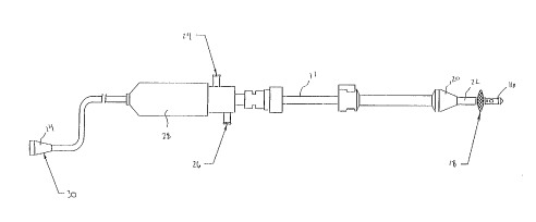
Referring now to Fig. 1, an exemplary embodiment of
a thermal ablation device 10 will be described. The thermal
ablation device 10 includes an elongate body 12 having a
proximal end 14 and a distal end 16. The elongate body 12 may
be constructed of a rigid material or a semiflexible material.
Disposed near the distal end 16 is a radially expansible
internal os seal 18. Axially spaced-apart from the internal
os seal 18 is an external os seal 20. Between the internal os
seal 18 and the external os seal 20 is a reduced diameter
neck 22 for receiving the cervix. Construction of the
internal os seal 18, the external os seal 20, and the neck 22
are described in copending Application Serlal No. 08/266,036,
filed June 27, 1994 (Attorney Docket No. 13178-27), the
disclosure of which is herein incorporated by reference.
CA 02230890 l998-02-27
W O 97/O9OI0 PCT~US96/13863
14
Operation of the seals 18 and 20 will be described in greater
detail hereinafter with reference to Figs. 5 and 6.
Disposed in the elongate body 12 is a fluid inflow
port 24 and a fluid outflow port 26 through which fluids may
be introduced and withdrawn, respectively, to and from the
uterus. The device 10 further includes a handle 28 which may
optionally include an internal motor which is employed to
circulate the fluid as described in greater detail
hereinafter. At the proximal end 14 iS a power supply
connector 30 for connecting the device 10 to a radio frequency
power supply as will be described in greater detail
hereinafter.
Referring to Fig. 2, the distal end 16 of the
device 10 will be described in greater detail. Distal to the
internal os seal 18 is a distal tip 32 of the elongate
body 12. The distal tip 32 may be constructed to be rigid or
may alternatively be deflectable. Alternatively, the distal
tip 32 may be angled relative to the elongate body 12. The
distal tip 32 includes mixing inlets 34 and mixing outlets 36.
As will be described in greater detail hereinafter, fluid
within the uterus is drawn through mixing inlets 34, is heated
within the device 10, and is then expelled back into the
uterus through mixing outlets 36. A vent inlet 38 is provided
and is in communication with the fluid outflow port 26 and
serves to dampen pressure variations occurring within the
uterus. The distal tip 32 is further provided with a blunt
portion 40 to prevent tissue trauma when inserting the
device 10 into the uterus.
Referring to Figs. 3, 3A and 4, construction of the
distal tip 32 will be described in greater detail. When fluid
is introduced into the fluid inflow port 24, it passes through
a pair of fluid inflow lumens 42 as illustrated by the dashed
arrows. The incoming fluid exits the inflow lumens 42 and
enters a heating chamber 44. Held within the heating chamber
are a pair of spaced-apart ring electrodes 46, 48. Distal to
the electrode 48 is an impeller 50. As fluid enters the
heating chamber 44 from the inflow lumens 42, it passes
through the electrode 46 and exists the chamber 44 through the
CA 02230890 1998-02-27
W O 97/09010 PCTAUS96/13863
mixing inlets 34 and mixing outlets 36. As fluid fills the
uterus, gasses are removed from the uterus through exit
ports 52 and into an annular fluid outflow lumen 54 where it
may be withdrawn through the outflow port 26.
A multilumen tube 56 extends through the elongate
body 12 and includes the fluid inflow lumens 42. A vent
ring 58 is provided to isolate the fluid inflow lumens 42 from
the fluid outflow lumen 54. The multilumen tube 56 further
includes an electrode wire lumen 60 which serves as a conduit
for electrode wires (not shown) connected to the
electrodes 46, 48 and extending to the power supply
connector 30.
To supply radio frequency current to the electrodes
46, 48, the power supply connector 30 is plugged into a
conventional radio frequency power supply. Preferably, radio
frequency current will be supplied at a frequency in that
range from 200 kHz to 300 kHz. When radio frequency power is
supplied to the electrodes 46, 48, current passes through the
fluid within the heating chamber 44 to heat the fluid between
the electrodes. The tubing of the elongate body 12 at the
distal tip 32 is preferably constructed of a dialectic
material so that the electrodes 46, 48 are electrically
isolated from the patient. This protects the patient from
unintended contact with the electrodes which may result in
electric burns and fouling of the electrodes. The
electrodes 46, 48 will preferably be constructed to maximize
the surface area of the electrodes and the gap between the
electrodes. The size of the electrodes 46, 48 and the
distance therebetween will preferably be made as large as
possible without exceeding size constraints for the distal
tip 32. Usually, the distal tip 32 will have an outer
diameter in the range from about 3 mm to 8 mm and a length in
the range from about 10 mm to 30 mm. Maximizing the surface
area and the gap increases the volume of fluid being heated by
the electrodes 46, 48. In this way, more fluid may be heated
more rapidly, and without fouling of the electrodes 45, 48.
As previously described, fluid is circulated through
the heating chamber 44 by the impeller 50. The impeller 50
-
CA 02230890 l998-02-27
W O 97/09010 PCTrUS96/13863
16
pulls fluid into the heating chamber 44 through the mixing
inlets 34 where it passes between the electrodes 46, 48 for
heating. The heated fluid then flows out of the device 10
through the mixing outlets 36 and circulates within the
uterine cavity. The impeller will be fashioned so that it
will efficiently pull fluid through the inlets 44 and expel
the fluid from the outlets 36 without causing pressure waves
within the uterus. Preferably, the impeller will be
constructed of a 180~ section of a coarse thread pitch screw.
A drive shaft 62 iS connected to the impeller 50 and extends
through a drive shaft lumen 64 of the multilumen tube 56. The
drive shaft 62 will preferably be constructed of a stainless
steel rod. Alternatively, the drive shaft 62 may be
constructed of a wound stainless steel or a flexible plastic.
A proximal end of the shaft 62 is connected to a DC electric
motor, which preferably spins the impeller in the range from
about 10,000 to 30,000 rpm, and more preferably, at about
25,000 rpm. As previously described, the DC electric motor
may be included within the handle 28 or may be separate from
the device 10. The drive shaft 62 iS preferably electrically
insulated, e.g. with teflon, to prevent current from traveling
through the sha~t which could reduce power input to the
thermally conductive fluid and present a shock hazard. The
impeller 50 is included within the elongate body 12 to prevent
it from causing tissue trauma.
The impeller 50 will preferably be operated without
substantially raising the intrauterine pressure. Preferably,
the impeller 50 will be configured to circulate the fluid
through the heating chamber 44 at a rate sufficient to ensure
that a narrow temperature differential is maintained between
the fluid within the heating chamber 44 and the fluid within
the uterus. Circulation of the fluid in this manner also
allows more energy to be input to the electrodes without
overheating the fluid between them.
The size and number of the mixing inlets 34 and
mixing outlets 36 will be configured to reduce the potential
of tissue or blood clots becoming clogged therein. In the
event that tissue or blood clots enter into the heating
CA 02230890 1998-02-27
W O 97/O9010 PCT~US96/13863
17
chamber 44, the impeller 50 will chop the tissue or clots into
small morsels to further increase heat transfer capacity of
the fluid.
The device 10 is further provided with at least one
temperature sensor 66 located on the outside surface of the
distal tip. The temperature sensor 66 may comprise a
thermocouple, a thermistor, or the like. The temperature
sensor 66 is located near the mixing inlets 34 so that the
temperature of the fluid entering the inlets 34 may be
detected. With information provided by the temperature
sensor 66, power to the electrodes 46, 48 may be controlled to
in turn control the intrauterine fluid temperature.
Preferably, the fluid will be heated until reaching a
temperature in the range from about 60~ C to 100~ C.
As best shown in Fig. 4, an internal temperature
sensor 68 is provided within the heating chamber 44 to monitor
the temperature within the heating chamber 44. In the event
that fluid is unable to circulate through the heating
chamber 44, the fluid between the electrodes 46, 48 can super
heat and exceed a desired maximum fluid temperature, usually
at or exceeding about 100~C. If such an event occurs, the
power to the electrodes 46, 48 may be shut off. Wiring for
the sensors 66 and 68 extends through a lumen 70 in the
multilumen tube 56 as best shown in Fig. 3A.
An alternative embodiment of a distal tip 32' is
illustrated in Figs. 4A-4D. The distal tip 32' is essentially
identical to the distal tip 32 of Figs. 3-4 except that the
distal tip 32' houses a double impeller 51 and has an
additional mixing inlets and outlets. The double impeller 51
is provided to increase fluid circulation within the uterine
cavity and thus improve heat distribution. The distal tip 32'
includes mixing inlets 34' which cooperate with mixing outlets
36' to circulate fluid through the mixing chamber 44' and past
the electrodes 46, 48 in a manner similar to that previously
described with the distal tip 32 of Figs. 3-4. The distal tip
32' further includes mixing inlets 35 which cooperate with
mixing outlets 37 to circulate fluid through a secondary
chamber 39. The impeller 51 pulls fluid through the mixing
CA 02230890 1998-02-27
W O 97/09010 PCT~US96~13863
18
inlets 35 and pushes the fluid out the mixing outlets 37.
This essentially doubles fluid circulation within the uterine
cavity and improves heat distribution. Preferably, the
impeller will be constructed of two centrifugal impellers
positioned back to back.
Referring to Figs. 5 and 6, introduction of the
thermal ablation device 10 into the uterus U through the
cervical canal CC will be described. As shown in Fig. 5, the
device 10 is transcervically introduced into the uterus U
until the internal os seal 18 passes entirely through the
cervical canal CC and into the uterus. An actuator 72 is then
distally advanced to radially expand the internal os seal 18
as illustrated in Fig. 6. The device 10 is then proximally
withdrawn to seat the internal os seal 18 against the internal
os of the cervix. The external os seal 20 is then advanced to
seat the seal 20 against the external os of the cervix, with
the neck 22 lying within the cervical canal CC. The external
os seal 20 is then locked to hold the seals 18, 20 in place.
Once a suitable seal is formed, fluid is introduced into the
uterus U through the inflow ports 24 as previously described.
When the uterus U is filled with the fluid, heating may then
proceed by energizing the electrodes as previously described.
In this way, heating occurs within the uterus U so that heated
fluid is not exposed to the cervical canal CC or to the
vagina.
Referring to Figs. 7-10, an exemplary method for
filling the uterine cavity U with a thermally conductive fluid
will be described. For convenience of discussion, reference
numerals used to describe the thermal ablation device 10 will
be used for like elements in the schematics of Figs. 7-10.
Operation of the thermal ablation device 10 to fill and
maintain fluid within the uterus U will preferably proceed in
a manner substantially identical to the procedure set forth
schematically in Fig. 7-10. To fill the uterus U with fluid,
an open fluid reservoir 74 having the fluid F is connected to
the fluid inflow lumen 42 as shown in Fig. 7. Preferably,
the fluid reservoir 74 will be elevated above the uterus U at
a height sufficient to produce the desired intrauterine
CA 02230890 l998-02-27
W O 97/09010 PCTAUS96/13863
19
pressure. Preferably, the open fluid reservoir 74 will be an
open saline bag that is elevated from about 16 inches to about
27 inches above the uterus to produce a pressure in the range
from about 30 mmHg to 50 mmHg within the uterus U. As fluid
flows through the inflow lumen 42, it enters the uterus U as
illustrated in Fig. 8. Air within the uterus U is expelled
through the outflow lumen 54. Optionally, the flow of fluid
through the inflow lumen 42 may be restricted relative to the
outflow lumen 54 to improve air removal from the uterus U.
Further, a tube 76 may be attached to the outflow lumen 54 and
hung below the uterus so that as fluid flows through the
tube 76 a vacuum will be generated in the uterine cavity
because of the restricted flow through the inflow lumen 42.
The vacuum will tend to collapse the uterine cavity and suck
the air from the uterus U. After the air is removed from the
uterus U, the outflow lumen 54 will be primed and may be
closed to allow the Eluid F in the reservoir 74 to pressurize
and distend the uterus U. If the intrauterine pressure
unexpectedly increases, the excess pressure will naturally
vent through the inflow lumen 42 and into the fluid
reservoir 74. Further, as previously described, the vent
inlet 38 on the device 10 is provided to allow undesirable
pressure variations to be vented back through the fluid
outflow port 26. In the unlikely event that fluid leaks from
the uterine cavity, the fluid reservoir 74 may be employed to
replenish the lost fluid to maintain the desired intrauterine
pressure. Optionally, the reservoir 74 may be provided with a
drip chamber 78 so that flow from the reservoir 74 can be
monitored and controlled. As illustrated in Fig. 10, once the
entire system is primed with the fluid F, the outflow tube 76
may be raised to the height of the fluid reservoir 74 to
maintain the desired intrauterine pressure.
Referring to Fig. 11, a wire coil 80 is shown in
cross-sectional view. The wire coil 80 may be employed as a
substitute for the electrodes 46 and 48 of the thermal
ablation device 10. To heat fluid using the wire coil 80,
high ~requency alternating current at a frequency in the range
from 100 kHz to 300 kHz is directed through the wire coil in
CA 02230890 1998-02-27
W O 97/09OlO PC~rUS96/13863
the direction indicated by the arrow 82. When electrical
current is passed through the wire coil 80 in this manner, a
magnetic flux is created. The magnetic flux distribution is
illustrated with elliptical circles in Fig. 11, with the
density of the flux being greatest inside the coil 80. The
varying magnetic flux within the fluid in turn causes eddy
currents in the fluid that generate heat. In this manner,
~1uid within the heating chamber 44 may be heated by the wire
coil 80.
Although the foregoing invention has been described
in detail for purposes of clarity of understanding, it will be
obvious that certain modifications may be practiced within the
scope of the appended claims.