Language selection

Search

Patent 2230930 Summary

Third-party information liability

Some of the information on this Web page has been provided by external sources. The Government of Canada is not responsible for the accuracy, reliability or currency of the information supplied by external sources. Users wishing to rely upon this information should consult directly with the source of the information. Content provided by external sources is not subject to official languages, privacy and accessibility requirements.

Claims and Abstract availability

Any discrepancies in the text and image of the Claims and Abstract are due to differing posting times. Text of the Claims and Abstract are posted:

  • At the time the application is open to public inspection;
  • At the time of issue of the patent (grant).
(12) Patent Application: (11) CA 2230930
(54) English Title: EXTERIOR REAR VIEW MIRROR INTEGRAL WARNING LIGHT
(54) French Title: RETROVISEUR EXTERIEUR AVEC CLIGNOTANT INTEGRE
Status: Dead
Bibliographic Data
(51) International Patent Classification (IPC):
  • B60R 1/12 (2006.01)
  • B60Q 1/26 (2006.01)
  • B60Q 1/32 (2006.01)
  • B60Q 1/34 (2006.01)
  • B60R 1/06 (2006.01)
(72) Inventors :
  • GATHERGOOD, DALE (United States of America)
  • STIDHAM, MARK (United States of America)
  • FURLOTTE, CHARLES (United States of America)
(73) Owners :
  • BRITAX RAINSFORDS, INC. (United States of America)
(71) Applicants :
  • BRITAX RAINSFORDS, INC. (United States of America)
(74) Agent: SMART & BIGGAR
(74) Associate agent:
(45) Issued:
(22) Filed Date: 1998-03-03
(41) Open to Public Inspection: 1998-10-25
Availability of licence: N/A
(25) Language of filing: English

Patent Cooperation Treaty (PCT): No

(30) Application Priority Data:
Application No. Country/Territory Date
08/837,866 United States of America 1997-04-25

Abstracts

English Abstract


An exterior rear view mirror assembly is disclosed which incorporates
a warning light actuatable in conjunction with the vehicle turn signals to alertadjacent motor vehicles of an anticipated turn. The warning light is integrated into
a first decorative cover member and may be connected to the vehicle turn signal
circuit by way of connectable electrical leads or by an integrally formed plug and
outlet arrangement. A second decorative cover member may be substituted for the
first decorative cover member when it is not desired to incorporate the warning
light.


French Abstract

Rétroviseur extérieur avec clignotant intégré actionné en même temps que les clignotants du véhicule et servant à signaler aux véhicules motorisés contigus que le conducteur s'apprête à faire un virage. Le clignotant est intégré dans un premier couvercle décoratif et peut être relié au circuit des clignotants du véhicule au moyen de fils électriques ou d'une fiche et d'une prise intégrées. Un second couvercle décoratif peut être substitué au premier lorsque le clignotant intégré n'est pas désiré.

Claims

Note: Claims are shown in the official language in which they were submitted.


CLAIMS
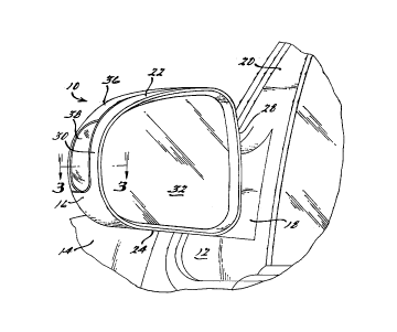
1. An exterior rear view mirror assembly comprising
a housing (16, 16' ) adapted to be secured to an outer
surface of a motor vehicle and having a generally
rearwardly facing opening, a mirror (32) disposed within
said opening, and a first decorative cover member (36, 82)
secured in overlying relationship to an outer surface
portion of said housing (16, 16'), characterised in that
said decorative cover member (36, 82) includes a light
transmitting window (56), a light assembly (38) having a
light source (46) therein, said light source (46) being
operable to provide a signal visible through said light
transmitting window (56) to an adjacent motor vehicle when
actuated.
2. An exterior rear view mirror assembly according to
claim 1, wherein said light assembly (38) includes a light
housing (40, 73), said light source (46) including a light
socket (44, 74) removably secured to said light housing
(40, 73).
3. An exterior rear view mirror assembly according to
claim 1 or 2, wherein said light assembly (38) is mounted
on said decorative cover member (36, 82).
4. An exterior rear view mirror assembly according to
claim 3, wherein said light assembly (38) is fixedly
secured to said decorative cover member (36, 82) .
5. An exterior rear view mirror assembly according to
any preceding claim, wherein said light transmitting window
is a lens (56) and said light housing includes a light
socket support member (40, 73) secured to said lens (56),
said lens (56) having an outer surface contour forming a
substantially smooth continuation of the outer surface of
said decorative member (36, 82).
6. An exterior rear view assembly according to claim
5, wherein said light socket support member (40, 73)
includes a reflective inner surface (64) shaped to direct
light emitted from said light source (46) to said lens
(56).


7. An exterior rear view mirror assembly according to
claim 5 or 6, wherein said lens (56) is operative to direct
light outwardly in a direction to be visible by other motor
vehicles following and travelling alongside side motor
vehicle.
8. An exterior rear view mirror assembly according to
claim 7, wherein said lens (56) is operative to direct
light through an arc extending substantially 90° rearwardly
from approximately a line passing through said mirror
assembly and extending perpendicular to the longitudinal
axis of said vehicle.
9. An exterior rear view mirror assembly according to
any preceding claim, including an electrical connector (52,
80) adapted to establish an electrical connection to said
supply source.
10. An exterior rear view mirror assembly according to
claim 9, wherein said electrical connector (52, 80) is
adapted to be electrically connected to said vehicle turn
signal system, said light source (46) including a mating
connector (54, 76) connected to said electrical connector
whereby said light source (46) may be actuated when said
vehicle turn signal is actuated.
11. An exterior rear view mirror assembly according to
claim 9 or 10, wherein said electrical connector (52, 80)
is accessible through an opening in said housing (16, 16')
which is covered by said decorative cover member (36, 82).
12. An exterior rear view mirror assembly according to
claim 9 or 10, wherein said housing (16') includes a cavity
(78) adapted to receive said light source (46), said
electrical connector (80) being located in said cavity
(78).
13. An exterior rear view mirror assembly according to
claim 12, wherein said electrical connector comprises an
electrical outlet (80) on a wall of said cavity (78).
14. An exterior rear view mirror assembly according to
any of claims 8 to 13, wherein said mating connector (76)
is integrally formed with said light source.


15. An exterior rear view mirror assembly according to
any of claims 9 to 14, wherein said mating connector
includes a pair of electrically conductive prongs (76)
projecting outwardly of said light housing (73), said
prongs (76) being connectable to said electrical connector
(80) upon assembly of said decorative cover member (82) to
said housing (16').
16. An exterior rear view mirror assembly according to
any preceding claim, wherein said housing (16) has an upper
wall portion (22), a lower wall portion (24), a forwardly
facing wall portion (26) and inner and outer wall portion
(28, 30) co-operating to define a generally enclosed area
leading from said rearwardly facing opening, and the
decorative cover member (36, 82) is received within and
substantially covers a recessed portion (34) which extends
over at least a part of said upper, forwardly facing and
outer wall portions (22, 26, 30).
17. An exterior rear view mirror assembly according to
any preceding claim, wherein said mirror assembly includes
a second decorative cover member (72), said second
decorative cover member (72) being interchangeable with
said first decorative cover member (36, 82) being secured
to said housing (16, 16') when said light assembly (38) is
not desired.
18. An exterior rear view mirror assembly according to
any preceding claim, wherein said mirror (32) is movably
positioned within said rearwardly facing opening.

Description

Note: Descriptions are shown in the official language in which they were submitted.


CA 02230930 1998-03-03


IOR REAR VIEW MIRROR
INTEGRAL WARNING LIGHT

Back~round and Sullll~ of the Invention
The present invention relates generally to rear view mirror assemblies
for motor vehicles and more particularly to exterior motor vehicle mirror
assemblies which incorporate auxiliary warning lights.
S Auxiliary warning lights have long been incorporated on the sides of
motor vehicles to provide a means of collllllunicating the intentions of the o~eralor
thereof to adjacent vehicles such as for example the intention to change traffic lanes
or to make a turn. Such lights are advantageous in providing notice to an adjacent
vehicle that may be located in a blind spot and positioned such that the sign~lling
vehicle's tail lights are not visible to the adjacent vehicle's operator.
While incol~o-dlion of such auxiliary warning lights is relatively easy
- and straightforward on work-type vehicles it becomes a somewhat more complex
problem when passenger-type vehicles are involved due in part to the importance
of aesthetic appearance. Other considerations which may apply to any type of
vehicle include the need to position the lights so as to minimi~e any impact on the
vision of the vehicle operator and to maximize the area to the side and rear of the
vehicle from which the auxiliary lighting is visible. Additionally, because in many
cases the vehicle m~nuf~rtnrer may want to offer the auxiliary li~hting arrangement
as an option on certain vehicles, it is highly desirable that the lighting system be
designed to easily and conveniently integrate with the existing vehicle design so as
to ~ e added labor and/or costs associated with its in~t~ tion.
The present invention provides a highly effective and aesthetically
pleasing auxiliary lighting system which is integrated into the vehicle's exterior rear
view mirror assembly. Preferably, the auxiliary warning light of the present
invention will be positioned on the laterally outer surface of the vehicle's exterior
rear view mirror in such a manner as to be visible throughout an arc e7~ten-lingabout 90 degrees rearwardly from a line extending generally perpendicular to thelon~itl1-iin~1 axis of the vehicle. In this manner m~ximllm visibility of the auxiliary
warning light is provided to vehicles coming alongside the equipped vehicle while

CA 02230930 1998-03-03


still ~ g the emitted light from being visible to the vehicle opeldlol or
v~ G ltraffic. Itshould be noted,- howeverj that the ~ ry w~lling lightmay
be positioned so as ~o be visible to ~ e ,traffic in addition ~o ~he above
rer~le.lced arc should this be desired and may in fact replace fender side marker
lights le.luiled in certain countries.
In one form the light is integrated into a removable decorative covering
which is secured to the mirror housing and a pigtail is provided for connecting the
light to a wiring harness in the interior of the mirror housing. In a mo~ifi~tion
of this embodiment, the decorative cover member incorporating the light assemblyis provided with a plug and the mirror housing inrh1des a receptacle whereby
electrical contacts on the cover member may be "plugged into" the receptacle as the
decorative cover member is fitted to the housing. This last arrangement further
reduces the costs associated with final assembly as no s~d~e effort is required to
make the electrical com~;lions for the auxiliary warning light. Further, the
integration of the light assembly into the decorative cover member greatly f~cilit~t~s
the offering of the auxiliary lighting feature as an option because only the
decorative cover member need be changed to add or delete this auxiliary lightingfeature.
Additional advantages and feaLules of the present invention will become
app~rellt from the subsequent description and the appended claims taken in
conjunction with the accompanying drawingsO

Brief Description of the Drawings
Figure 1 is a fragmentary perspective view of a side of a motor vehicle
having an exterior rear view mirror assembly incorporating an ~ ry warning
light provided thereon all in accordance with the present invention;
Figure 2 is a side view of the mirror assembly of Figure l;
Figure 3 is a section view of the mirror light assembly of Figure 1, the
section being taken along line 3-3 of Figure l;
Figure 4 is a perspective view of a mirror housing with alternative
decoldlive cover members shown in position for in~t~ tion thereon, all in
accordance with the present inverltion;

CA 02230930 1998-03-03


Figure 5 is a view of the back side of a decorative cover member
~having a light ~,se."bly ~c~-yolaled ltherein which inrl~l-les an int~ lly ~ormed
electrical <~onnect~r in arc ~ r'ance with the present invPr ~i~. n
Figure 6 is a view of a portion of a l~irror housing incol~ola~g an
S electrical outlet ~ pted to mate with the plug shown in Figure 5, all in accor~ce
with the present invention; and
Figure 7 is a plan view of a motor vehicle having mirrors in
accordance with the present invention secured to opposite sides thereof.

Description of the Preferred Embodiment
Ref~ll~g now to the drawings and in particular to Figures 1 and 7,
there is shown an exterior rear view mirror assembly in~ir~ted generally at 10
in~t~llP~l t)n the door 12 of a motor vehicle 14. Mirror assembly 10 is of the
typical breakaway design and includes a housing 16 pivotably supported on an arm18 eYt~n-ling outwardly from a generally tri~ng~ rly shaped mounting plate 20.
As shown in Figure 7, preferably two mirrors 10 will be mounted on a vehicle 14,one on each side thereof.
Housing 16 may be of any desired shape and includes an upper wall
portion 22, a lower wall portion 24, a forwardly facing wall portion 26 and inner
and outer wall portions 28 and 30 all of which merge smoother together so as to
present a pleasing appearance. The rearwardly facing portion of housing 16 is open
and is adapted to receive a reflective mirror 32. Mirror 32 may be either of anysuitable type such as flat, concave or convex or of the type which autom~ti~lly
adjusts to reduce glare. A suitably shaped support member (not shown) is securedwithin the housing and serves to movably support mirror within the opening. The
support member may include suitable drive motors and the like for remote controladJll~trnent of mirror as well as means for heating the mirror if desired. Housing
16 also contains a recessed portion 34 e~tenfling over at least a part of upper,inner, outer and forwardly facing portions 22, 28, 30 and 26 which is adapted toreceive a decorative cover member 36 which cover member may be chromed,
colored to match the vehicle or of some other finish to present an aestheticallyplP~in~ appearance.

CA 02230930 1998-03-03


As thus far descrihe(1, mirror ~ mhly 10 is typical of exi~ting rear
~iew m~rror assemblies ~ llly employed on various motor vehides. ~Iowever,
mirror~ _.~ly 10~fthepresent; ~ ionalso~nc~ly~ an~llxili~ry~ g
light assembly 38 ih-le~ldted with the decorative cover member 36.
S As best seen with re~lellce to Figure 3, auxiliary warning light
assembly 38 includes a light housing co.l.p.isillg a base member 40 having an
opening 42 therein which is adapted to receive a suitable electrical socket 44 having
a light source 46 provided thereon. Preferably opening 42 will be desi~n~d with
two or three radially uulw~dly and circumferentially extending open portions
whereby segm~nted inner flange 48 of light socket 44 may be inserted and then
turned a few degrees to lock it in place. It should be noted that any suitable
available light source 46 may be lltili7ec1 A suitable pigtail and associated
electrical conne-;lur 50 is also provided ~ ng uulw~dly from socket 44 which
is adapted to be col-ne~led to colulector 52 of wiring harness 54 provided in
housing 16. A lens member 56 is secured to base member 40 and is clesign~d so
as to direct light emitted from light source outwardly from mirror housing through
an arc 58 exten~ing approximately 90 degrees rearwardly from a line 60 passing
through the mirror 10 and extending substantially perpendicular to the longitlldin~l
axis 62 of the motor vehicle 14. In order to enhance the visible light tr~n~mitted
by the lens 56 the inner surface 64 of base member 40 will preferably be coated
with a reflective material and shaped so as to direct a m~ximllm amount of lightfrom the light source 46 to the lens 56.
Light assembly 38 will preferably be me~h~niç~lly secured to
decorative cover member 36 by means of integrally formed snap fasteners so as toform a one-piece assembly therewith. Although any other suitable manner of
securing light assembly 38 to decorative cover member 36 may be used such as forexample adhesive bonding, sonic welding, molding or even suitable sepalat~
fasteners. It is desirable that lens 38 have an outer surface which is shaped so as
to form a substantially smooth contim~tion of the outer contour of decorative cover
member as is shown in Figures 1 and 2.
In order to accommodate light assembly 38, housing 16 is provided
with an opening 66 on the recessed part of outer surface portion 30 which nntl~rli~s

CA 02230930 1998-03-03


;ve member 36. While housing 16 is shown as providing an opening 66 to
~rs3~.. nrl t~ lig_t ~embly 38, -~in 60me applicaliolls it may be desil~ble to provide
an endosed recess ~n place ~er~f. l~d-1itinn~l1y., as r~nti~n~ above a wiru~g
h~rnPss 54 having a suitable electrical connector 52 will be provided within housing
16 so as to be ~c~es~ihle through opening 66 or within the recess if such is
provided in place of the opening 66.
In order to assemble decorative member 36 and associate light
assembly 38, one need merely interconnect the two electrical connectors 50, 52 and
the~arler assemble decorative member 36 to housing 16. As shown in Figure 4,
decorative member 36 is provided with a plurality of spaced outwardly exten~ing
tangs 68 on the back surface 70 thereof. These tangs 70 are cle~ cl to be
received within suitable openings provided in housing 16 and to cooperate with
latch ~ Q~ provided therein to retain the decorative lllelllb.,l 36 thereon in the
same manner as in ~;ull~ ly available mirror assemblies of this type.
Warning light assembly 38 is int~nf1el1 to be interconn~ct~d with the
vehicle turn signal system so that when one or the other of the turn signals areachl~ted, the light assembly 38 provided on the exterior mirror on the
corresponding side of the vehicle will also be ~ tecl In this manner any other
vehicle that may be approaching the vehicle equipped with the subject invention or
that may be traveling in its blind spot will immediately be appraised of the
equipped vehicle's intention to turn or change lanes even though they may not bein a position to see the vehicle tail lights. However, because the light is positioned
on the outer wall portion 30 of the mirror assembly, the housing 16 and mirror 32
will prevent the driver of the vehicle from being distracted by this light when
~tll~t~-l
As previously mentioned, the subject invention is particularly well
suited for offering of the auxiliar~ warning light as an optional accessory by vehicle
m~n~lf~ctllrers. As shown in Figure 4, the overall size and shape of the decorative
member 36 incorporating the light assembly 38 is such that it may be easily and
conveniently interchanged with a decorative member 72 which does not include thelight assembly. Thus, during final assembly of the mirror, the assembler need
merely select one or the other of the two decorative cover members 36, 72 for

CA 02230930 1998-03-03


A~ ,,.rnl to the mirror housing 16 depending upon the desires of the int~n~
.;U~ Further, - should a i~ulchasel of a vehicle decide at a later date to either
add ~r del~e ~the AllxiliAry ~i~hting fP~~llr~ it is only nPr~ .y to replace thedecoraliv~ cover member 36 or 72 with the other cover llltlllber.
Re~llmg now to Figures 5 and 6, another embodiment of the subject
invention is disclosed which further f~rilhAtes rapid and low cost assembly of the
subject invention. In this embodiment, base member 40, light socket 44 and
connPctc r 50 are replaced by a base member 73 and a light socket 74 having a pair
of electrically conductive pins 76 extending l)ulw~dly thelerlvlll. Mirror housing
16' is also modified by replacing opening 66 with a molded-in cavity 78 in whicha pair of spaced ope~lgs 80 are provided position~d so as to receive pins 76 when
decorative member 82 is assembled thereto. Thus, with this embodiment the
asselllbleI need not first hl~ co~e~,~ the two electrical co~eclors 50, 52 but rather
needs merely install the decoIaLive cover member 82 during which pins 76 will bereceived within openings 80 thereby elPctrirAlly connPcting light assembly to the
existing vehicle turn signal system. As with the previous embodiment, should a
purchaser not desire to include the light assembly, a cover member without the
light assembly included is easily assembled to mirror housing 16 and will cover and
conceal cavity 78 provided therein.
While it will be appalelll that the ple~lled embodiments of the
invention disclosed are well calculated to provide the advantages and feaLures above
stated, it will be appreciated that the invention is susceptible to modification,
variation and change without departing from the proper scope or fair me~ning of
the subjoined claims.

Representative Drawing
A single figure which represents the drawing illustrating the invention.
Administrative Status

For a clearer understanding of the status of the application/patent presented on this page, the site Disclaimer , as well as the definitions for Patent , Administrative Status , Maintenance Fee  and Payment History  should be consulted.

Administrative Status

Title Date
Forecasted Issue Date Unavailable
(22) Filed 1998-03-03
(41) Open to Public Inspection 1998-10-25
Dead Application 2003-03-03

Abandonment History

Abandonment Date Reason Reinstatement Date
2000-03-03 FAILURE TO PAY APPLICATION MAINTENANCE FEE 2000-03-21
2002-03-04 FAILURE TO PAY APPLICATION MAINTENANCE FEE

Payment History

Fee Type Anniversary Year Due Date Amount Paid Paid Date
Registration of a document - section 124 $100.00 1998-03-03
Application Fee $300.00 1998-03-03
Reinstatement: Failure to Pay Application Maintenance Fees $200.00 2000-03-21
Maintenance Fee - Application - New Act 2 2000-03-03 $100.00 2000-03-21
Maintenance Fee - Application - New Act 3 2001-03-05 $100.00 2000-12-21
Owners on Record

Note: Records showing the ownership history in alphabetical order.

Current Owners on Record
BRITAX RAINSFORDS, INC.
Past Owners on Record
FURLOTTE, CHARLES
GATHERGOOD, DALE
STIDHAM, MARK
Past Owners that do not appear in the "Owners on Record" listing will appear in other documentation within the application.
Documents

To view selected files, please enter reCAPTCHA code :


To view images, click a link in the Document Description column. To download the documents, select one or more checkboxes in the first column and then click the "Download Selected in PDF format (Zip Archive)" or the "Download Selected as Single PDF" button.

List of published and non-published patent-specific documents on the CPD .

If you have any difficulty accessing content, you can call the Client Service Centre at 1-866-997-1936 or send them an e-mail at CIPO Client Service Centre.


Document
Description 
Date
(yyyy-mm-dd) 
Number of pages   Size of Image (KB) 
Representative Drawing 1998-11-10 1 10
Abstract 1998-03-03 1 16
Description 1998-03-03 6 307
Claims 1998-03-03 3 132
Drawings 1998-03-03 3 81
Cover Page 1998-11-10 1 45
Assignment 1998-03-03 9 305