Note: Descriptions are shown in the official language in which they were submitted.
CA 02230977 1998-03-03
VEHICLE DIAGNOSING APPARATUS
BACKGROUND OF THE INVENTION
1. Field of the Invention
The present invention relates to a vehicle
diagnosing apparatus which diagnoses a vehicle via an
electronic control unit (ECU) which is mounted on the
vehicle.
2. Description of the Related Art
As this kind of vehicle diagnosing apparatus, there
has hitherto been known the following one in Japanese
Published Examined Patent Application No. 18780/1995.
Namely, the vehicle diagnosing apparatus is connected to
an electronic control unit which is mounted on a vehicle,
and the vehicle is diagnosed by incorporating (or
receiving), via the electronic control unit, detected
signals from various sensors which are disposed in the
vehicle. When a signal which demands the transmission of
data is transmitted from the vehicle diagnosing apparatus
to the electronic control unit, the detected signals from
the sensors that meet the requirements of the demand are
transmitted to the vehicle diagnosing apparatus. The
vehicle is then diagnosed based on the detected signals.
There has also been known the following vehicle
diagnosing apparatus in Japanese Published Examined Patent
Application No. 18779/1995. Namely, for example, the
1
CA 02230977 1998-03-03
state (or condition) of depressing an accelerator pedal,
and an air/fuel ratio which is obtained by a signal
detected by an 02 sensor are respectively detected as
digitized data. If the air/fuel ratio is switched from a
lean state to a rich state by a change in the state of
depressing the accelerator pedal from a non-depressed
condition to a depressed condition, a judgement is made
that the vehicle is in a normal condition.
In the former example of the above-described
conventional apparatuses, it is necessary to set in
advance, before the vehicle is diagnosed, the timing of
transmitting the signal which demands the transmission of
data. For example, in case the timing of incorporating
the detected signals is set theoretically by making the
lapse of time to serve as a parameter, it is necessary to
make the setting, by referring to the design data of the
vehicle, such that the detected signals can be
incorporated surely and stably at timings with sufficient
allowance in time. Therefore, it requires unnecessarily
long time before the incorporation of the detected signals
is completed, with the result that the diagnosing time
becomes long. It is conceivable to continuously
incorporate the detected signals from various kinds of
sensors over a wide range prior to the diagnosing and then
to set in advance the most appropriate timings of
incorporating the detected signals from the state of
changes in the detected signals. However, this solution
2
CA 02230977 2004-10-20
' requires a separate apparatus for the purpose of setting
the timings.
In the latter example of the above-described
conventional apparatus, on the other hand, since the
diagnosis is performed by means of digitized data, a
judgement cannot be made about the timing at which the
digitized data are switched. It follows that an accurate
diagnosis cannot be performed. In other words, for
example, even if the air/fuel ratio is judged to have been
switched to the rich state by depression of the
accelerator pedal, the vehicle cannot surely be judged to
be normal unless there is known the timing at which the
lean state is switched to the rich state.
Therefore, in view of the above-described problems,
the present invention has an object of providing a vehicle
diagnostic apparatus in which the detected signals can be
incorporated at most appropriate timings without using a
separate apparatus, and in which more accurate diagnosis
than diagnosing by means of digitized data can be
performed.
Therefore, according to a first aspect of the
present invention, there is provided a vehicle
diagnostic apparatus, which is connected to an
electronic control unit mounted on a vehicle; the
apparatus diagnosing the vehicle by incorporating
detected signals, via that electronic control unit, from
various sensors which are disposed in the vehicle. The
3
CA 02230977 2004-10-20
apparatus comprises: means for continuously receiving
the detected signals before starting the diagnosing:
means, operably coupled to the continuously-receiving
means, for displaying as a graph a state of changes in
the detected signals; and means, operably coupled to the
dis la in means, for receivin and for settin
p y g g g, on the
displayed graph, timings of incorporating the detected
signals used for diagnosis.
According to a second aspect of the present
invention, there is provided a vehicle diagnostic
apparatus comprising: means for incorporating detected
signals from a first sensor for detecting an operation
amount of an operating portion of the vehicle and from a
second sensor for detecting an amount of change-in-state
of an operated portion, the state of the operated
portion being changed by an operation of the operating
portion; and means, operably coupled to the
incorporating means, for diagnosing an interlocking
relationship between the operating portion and the
operated portion, the diagnosis being made from the
detected signal of one of those first and second sensors
at a point-in-time when the detected signal of the other
of those first and second sensors satisfies a
predetermined condition, the paint-in-time being set in
the diagnosing means.
The timings for incorporating the detected signals
shall preferably be set not theoretically but on the basis
of the state of changes in the actually detected signals,
because the time for diagnosing can thereby be shortened.
However, if a separate apparatus is required for setting
4
CA 02230977 1998-03-03
the timing, it takes time and expense for the setting. On
the other hand, the diagnosing apparatus is provided with
a function for incorporating the detected signals.
Therefore, according to the first aspect of the present
invention, the following arrangement has been made.
Namely, the diagnosing apparatus itself is provided with a
function for setting the timings, and the detected signals
are incorporated over a wide range before starting the
diagnosing. Then, from the state of changes in the
detected signals that have been incorporated, there is set
a most appropriate timing for incorporating the detected
signals used for diagnosing.
Further, suppose that the accelerator pedal is
defined to be the operating portion, changes will occur to
such states as an air/fuel ratio and the rotational
frequency of the engine which is defined to be the
operated portion. Therefore, according to the second
aspect of the present invention, the diagnosing of the
vehicle is made not by whether the accelerator pedal is
depressed or not but by detecting to what degree the
accelerator pedal has been depressed.
HRIEF DESCRIPTION OF THE DRAWINGS
The above and other objects and the attendant
advantages of the present invention will become readily
apparent by reference to the following detailed
description when considered in conjunction with the
5
CA 02230977 1998-03-03
accompanying drawings wherein:
FIG. 1 is a schematic diagram to show the
arrangement of one example of the present invention;
FIG. 2 is a graph to show one example of a display
for setting the timing of incorporating the data; and
FIG. 3 is a graph to show the relationship between
the rotational frequency NE of the engine and the throttle
opening TH.
DETAILED DESCRIPTION OF A PREFERRED EMBODIMENT
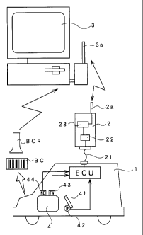
With reference to FIG. 1, reference numeral 1
denotes a vehicle on which an electronic control unit
(ECU) is mounted. Reference numeral 2 denotes a portable
diagnosing unit which is connected via a cable 21 to the
electronic control unit on the vehicle 1. The vehicle 1
has indicated thereon a vehicle number which is peculiar
to each vehicle in the form of a bar code BC. The bar
code BC is read by a bar code reader BCR. In the vicinity
of the vehicle 1, there is disposed a host computer 3.
Hidirectional wireless communication is performed between
the diagnosing unit 2 and the host computer 3. This
bidirectional wireless communication between the
diagnosing unit 2 and the host computer 3 is performed by
means of an antenna 2a which is provided in the diagnosing
unit 2 and an antenna 3a which is connected to the host
computer 3.
The diagnosing unit 2 contains therein a data buffer
6
CA 02230977 1998-03-03
22 which temporarily stores the detected signals read from
the electronic control unit and various data, and a
communication portion (or module) 23 which transmits to
the host computer 3 the detected signals or the like
stored in the data buffer 22. Upon receipt of the data
from the diagnosing unit 2, the host computer 3 analyzes
the data to fudge whether the vehicle is normal or not.
The results of diagnosing are recorded together with the
other data such as the vehicle number or the like.
The vehicle 1 has mounted thereon an engine 4 and is
provided with the following sensors, i.e., a throttle
sensor 42 which detects a throttle opening TH from the
amount of depression of an accelerator pedal 41, a water
temperature sensor 43 which detects the temperature of the
engine cooling water TW, and a rotational frequency sensor
44 which detects the rotational frequency (or rotational
speed) of the engine NE. These various sensors 42, 43, 44
are connected to the electronic control unit, and the
defected signals from each of these sensors 42, 43, 44 are
outputted from the electronic control unit to the
diagnosing unit 2. When the host computer 3 incorporates
the detected signals required for diagnosing, a signal
which demands the transmission of data is transmitted to
the electronic control unit via the diagnosing unit 2, and
the detected signals of the required sensors are
incorporated as the data. Therefore, before starting the
diagnosing, it is necessary to set the timing for
7
CA 02230977 1998-03-03
incorporating the detected signals as the data. For
example, as shown in FIG. 2, the detected signal from the
cooling water temperature sensor 43 increases, after the
engine 4 has started, from TW1 up to TW2 at an inclination
of S and is, thereafter, maintained at a constant value by
the operation of a radiator. In order to perform the
diagnosing, the inclination S and an average value of TW
in a predetermined period of time tv are obtained.
Diagnosing is performed by seeing whether both fall within
normal ranges which are set in advance. First, in order
to obtain the inclination S, it is necessary to set the
timing of incorporating TW1 and TW2. The host computer 3
has a timing setting function for setting the timing of
incorporating TW1 and TW2. Before starting the
diagnosing, the engine 4 is operated, and the detected
signal from the cooling water temperature sensor 43 is
continuously incorporated into the host computer 3, and is
displayed in the form of a graph similar to that shown in
FIG. 2. By looking at the graph displayed in the host
computer 3, the operator sets tl, t2 which are the
incorporating timings for obtaining the inclination S and,
also, sets t3 and t4 which are the timings for obtaining
the average value. Once the timings tl, t2, t3 and t4
have been set as described above, the host computer 3
transmits to the diagnosing unit 2 the signal which
demands the transmission of data at the time of diagnosing
at these set timings. Then, from the values TW1, TW2 of
8
CA 02230977 1998-03-03
TW that are incorporated at the timings of tl and t2, the
inclination S is obtained by (TW2 - TW1) / (t2 - tl).
Further, there is obtained an average value of the values
TW that are incorporated between the timings t3 and t4.
An explanation will hereinafter be made about an
example in which diagnosing is made of the relationship
between the amount of depression of the accelerator pedal
41 which is defined to be an operating portion, and the
rotational frequency NE of the engine 4 which is defined
to be an operated portion. With reference to FIG. 3, the
detected signal from the throttle sensor 42 is outputted
as a change in voltage V as shown by a curve A. In order
for the output to correspond to the rotational frequency
NE of the engine 4, the detected signal A is multiplied by
a function to thereby convert it to the throttle opening
TH as shown by a curve B. On the other hand, the
rotational frequency NE from the rotational frequency
sensor 44 is also incorporated. Then, a relative maximum
value NEm of the rotational frequency NE is obtained, and
there is obtained the throttle opening value THm which
corresponds to the point of time tm at which the
rotational frequency NE becomes the relative maximum value
NEm. The diagnosis is made by fudging whether the
throttle opening value THm falls within a predetermined
range which has been set in advance.
As can be seen from the above-described
explanations, according to the present invention, the
9
CA 02230977 2004-10-20
' timings for incorporating the detected signals from
various sensors can most appropriately be set without
using a separate apparatus. Further, since the diagnosing
of the vehicle is performed not by digitized data but by
continuous data, the diagnosing can be performed
accurately.
It is readily apparent that the above-described
vehicle diagnosing apparatus meets all of the objects
mentioned above and also has the advantage of wide
commercial utility. It should be understood that the
specific form of the invention hereinabove described is
intended to be representative only, as certain
modifications within the scope of these teachings will be
apparent to those skilled in the art.