Note: Descriptions are shown in the official language in which they were submitted.
CA 02231035 1998-03-03
1. TITLE OF THE INVENTION
GA:i TURBINE BLADE
2. FIELD OF THE INVENTION AND RELATED ART STATEMENT
ThE~ present invention relates to a gas turbine blade in
which a blade tip end is cooled effectively.
As shown in FIG. 4, a cooled blade used for a high-
temperature gas turbine i;s provided with a protrusion lOla at
the tip End of a gas turbine blade 102. This protrusion lOla
has a sealing effect such that a gap between the tip end of
the gas turbine blade 102 and a turbine blade ring 103 as
shown in FIGS. 5 and 6 is minimized to keep the quantity of
main flow gas which leaks and causes a turbine loss to a
minimum, and also is provided as an allowance so that even if
the tip End of the turbine blade 102 comes into contact with
the turb_Lne blade ring 10:3 due to thermal deformation etc., a
trouble :such that the blade is damaged, the cooling medium is
dischargE:d from the blade cooling passage, and the burning of
blade occurs is prevented. This conventional protrusion lOla
is provided on the extension of blade profile over the whole
periphery of outer surface of the blade tip end face and has
the same shape as that of the blade 102 as shown in FIGS. 4
and 5.
Conventionally, a cooled blade for a gas turbine, in
which cooling is effected by allowing a cooling medium to
- 1 -
CA 02231035 1998-03-03
flow in a cooling passage in the blade, has been used. As
the turbine inlet temperature and pressure are increasing
year by year to improve the gas turbine performance, the
thermal 7_oad on the cooled blade for gas turbine increases.
Therefore:, the blade meta:L temperature is decreased to
prevent burning. As a re:;ult, however, a very large
temperature gradient occurs in the blade metal. For this
reason, t:he protrusion lO:La as shown in FIG. 4 is provided at
the tip E:nd of the gas turbine blade. In this case, since
1.0 the distance from the coo:Ling surface formed on the surface
of cooling passage in the blade is large, the metal
temperature at the tip end of protrusion is very high, so
that theme is a possibility of occurrence of burning and a
crack formed by the thermal stress caused by a temperature
1.5 difference between the blade metal and the cooling portion.
For this reason, as shown in FIG. 6, a cooling medium
106 is ejected from a cooling passage 104 provided in the gas
turbine glade 102 through film cooling holes 105 so that the
cooling medium 106 is directed toward the blade tip end and
20 the turbine blade ring 103 at the side outside the blade, by
which a low-temperature cooling medium film is formed to cool
the gas turbine blade 102. However, since the ejected
cooling medium 106 causes the turbine performance to
decrease, the quantity of the ejected cooling medium 106 must
25 be restricted.
- 2 -
CA 02231035 2001-O1-15
21326-215
3. OBJECT AND SUMMARY OF THE INVENTION
An object of the present invention is to solve the
problems with the above-described conventional gas turbine
blade.
In accordance with the present invention, there is
provided a gas turbine blade comprising: a blade having a tip
end portion defined by arcuate spaced-apart wall portions which
generally oppose one anather and a cooling passage formed in
the blade tip end portion between the wall portions, the wall
portions having outer surfaces which collectively define a
blade profile, the blade further including a tip end wall which
extends between the blade wall portions at the tip end portion
of the blade; and a protrusion formed on an outer surface of
the tip end wall, said protrusion having a shape corresponding
generally to said blade profile and being defined by a
substantially closed wall comprising opposed spaced apart wall
portions positioned on said end wall inwardly of the blade
profile and directly above said cooling passage wherein said
cooling passage is closed at said tip end portion of said
blade.
The present invention provides a gas turbine blade
provided with a cooling passage therein, in which a protrusion
is provided on the inside from the extension of blade profile
on the outer surface of blade tip end.
According to the present invention, the protrusion is
provided on the inside from the extension of blade profile on
the outer surface of blade tip end so as to be close to the
cooling passage in the gas turbine blade above the cooling
passage, so that the distance from the blade cooling passage,
which is a cooling surface, is short as compared with the
3
CA 02231035 2001-O1-15
21326-215
conventional gas turbine blade, by which the metal temperature
of the protrusion tip end is decreased. This decrease in
temperature prevents the burning of gas turbine blade metal.
Also, since the material strength is relatively increased as
compared with the conventional gas turbine blade, and the
thermal stress is decreased by the decrease in temperature
difference between the blade metal and the blade cooling
portion, a crack at the blade tip end can be avoided.
According to the gas turbine blade in accordance with
the present invention, the protrusion provided on the inside
from the extension of blade profile on the outer surface of
3a
CA 02231035 1998-03-03
blade tip end can enhance the cooling performance of the gas
turbine blade, which contributes to the increase in
reliability without impairing the performance of the whole
plant.
4. BRIEF DESCRIPTION OF THE DRAWINGS
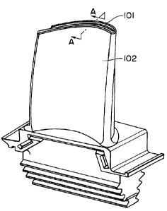
FIG. 1(a) is a perspective view showing a first
embodiment of a gas turbine blade in accordance with the
present 9.nvention, and FI(3. 1(b) is a plan view of the tip
1.0 end of the gas turbine blade;
FICi. 2 is a sectional view taken along the line A-A of
FIG. 1(a);
FIG. 3 is a sectional view of the tip end of a gas
turbine blade in accordance with a second embodiment of the
1.5 present invention;
FIG. 4(a) is a perspective view of a conventional gas
turbine blade, and FIG. 4(b) is a plan view of the tip end of
the convE:ntional gas turb:Lne blade;
FIG. 5 is a sectional view taken along the line H-H of
~0 FIG. 4, at the tip end of the conventional gas turbine blade;
FIG. 6 is a section~31 view of the tip end of the
conventional gas turbine blade provided with film cooling
holes; and
FIG. 7(a) is a diagram showing the metal temperature of
25 the bladE: tip end and protrusion of the gas turbine blade of
- 4 -
CA 02231035 1998-03-03
the first: embodiment in accordance with the present invention
and the conventional gas turbine blade shown in FIGS. 4 and
5, FIG. l(b) is a schemat:Lc view showing a distance from the
cooling surface at the blade tip end of the conventional gas
turbine blade, and FIG. 7(c) is a schematic view showing a
distance from the cooling surface at the blade tip end of the
gas turbine blade of the present invention.
5. DETAILED DESCRIPTION O1' PREFERRED EMBODIMENTS
1.0 A first embodiment of a gas turbine blade in accordance
with the present invention will be described with reference
to FIGS. 1 and 2. In thi:a embodiment, a cooling passage 104,
which is the same as that of the conventional gas turbine
blade shown in FIGS. 4 and 5, is provided in a gas turbine
1.5 blade 10~'., and a protrusion 101 protruding toward a turbine
blade ring 103 is provided on the outer surface of the tip
end face of the gas turbine blade 102.
ThE: protrusion 101 :is provided so as to be
substantially similar in ahape to the blade profile and round
20 the tip e:nd of the blade :L02, but it is positioned on the
inside from the extension of blade profile. Also, the height
of the protrusion 101 is determined so that a gap between the
protrusion 101 and the turbine blade ring 103 is minimized.
In this embodiment, the protrusion 101, which is
~:5 substantially similar in ahape to the blade profile, is
- 5 -
CA 02231035 1998-03-03
provided so as to be posiltioned on the inside from the
extension of blade profile on the outer surface of blade tip
end face. Therefore, the protrusion 101 is positioned above
the cooling passage 104 so as to be close to the cooling
passage 7.04, which can decrease the metal temperature of the
protrusion 101.
FIG. 7 shows the metal temperature at the blade tip end
near the protrusion of this embodiment and a conventional
example shown in FIGS. 4 and 5. As indicated by the solid
1.0 line in FIG. 7(a), in thi:~ embodiment, the metal temperature
of the tip end of the gas turbine blade 102 and the
protrusion 101 can be decreased as compared with the
conventional example indicated by the broken line.
Thereupon, the burning of the gas turbine blade 102 can be
1.5 avoided, and the occurrence of a crack at the tip end of the
gas turbine blade 102 can be avoided by relatively increasing
the material strength and decreasing the thermal stress.
A second embodiment of a gas turbine blade in
accordance with the present invention will be described with
20 reference' to FIG. 3. In 'this embodiment, one linear
protrusion 101' protruding toward the turbine blade ring 103
is provided along the blade width center on the outer surface
of the end face of the gaa turbine blade 102 in place of the
protrusion 101 in the firat embodiment of the present
25 invention.
- 6 -
CA 02231035 1998-03-03
Th~_s embodiment achieves the same operation and effects
as those of the first embodiment of the present invention.
Ali:hough one linear protrusion 101' is provided along
the blade width center on the outer surface of the end face
of the gas turbine blade :102 in the second embodiment of the
present invention, a plurality of protrusions may be provided
along the, blade width on 'the inside from the extension of
blade profile on the outer surface of the end face of the gas
turbine blade 102.