Note: Descriptions are shown in the official language in which they were submitted.
CA 02231350 1998-03-06
.
Description
Half-Timber ~rame and I lalf-Timber ComPartment Ele~nent
s
The invention ~oncerns a half-ti~ber frame for
6upporting a compartment element in accordance ~ith the
prea~ble of claim 1, wall elements for a like half-timber
lo fr~me and a method for producing a co~partment element.
Hal~-timber constr~ction has been e~ployed ~or
centurie6 to construct domestic buildLngs, wherein one
half-tim~er frame interstice i5 formed by vertical
members, trans~erse members l~t~p member, bottom member)
and possibly diagonal me~bers and filled ~ith suitable
wall or compartment elements Whereas the half-timber
frame is de~igned with a ~iew to static stren~th, the
compart~ent' elements are gen.erally adapted for op~imum
thermal insulation. In old half-~imber constructions
these compartment elements were formed of clay/brick
elements or other mineral conscruction ~aterials.
:ZS
~o~adays the half-timber constr~ction method can still be
found in ~ooden structures, ~ith the half-ti~ber frame
being produced o~ solid wooden beams, whereas the
compart~ent elements are co~monly comprised of t~o panel-
type sheathing layers spaced apart from each o~her, andthe space between these sheathing layers being filled by
loose fill or foamed insulation
~or producing the half-timber supports for the h~lf-
CA 02231350 1998-03-06
- timber ~rame, beams representing the core wood of small-
dimension ti~be~ are used, so that a certain minimum
thickness of the log is reql~ired for obtaining a beam
having the predetermined dimerlsions ancl the predetermined
strength. To this end the external layers o~ the tree
must be ~a~ed off until the parallelepipedic base shape
of the beam having smooth outer surfaces is obtained.
This production methocl has the drawback of giving rise to
consider~ble amount~ of logging waste which, at ~est, is
generally further comminuted and processed into chip
boards or other low-quali~y products.
The half-ti~ber frame construction method in its
conventional form moreover requires careful dryi~g of the
hearwood of small-dimension timbers, because in the case
of insufficiently dried half-timber supports there is a
risk of the~r ~arping owing to ~ariations of t~mperature
~() and humidity, and o~ the half-timber walls consequen~ly
developing cracks.
It i5 a drawback of the compartment elements employed in
the conventional half-timber frame constructi~n method
that only an inadecIuate strength may be obtained. In the
cases of loose fill insulation and foam insula~ion the
interstices ~a~ happen to be not filled entirely, whereby
only an insufficient or non-uniform insulation ef~ect can
be o~ained. In particular compartment elements
c~ntaining loose filling mat.e~ial can subsequently be
wc~rked only at greatest diffic-llty because any cutting to
~he compartment ele~ent may bring about at least partial
leaking of the filling material. It is another drawback
Qf the known compartment elements ~hat small anLmals,
CA 02231350 1998-03-06
- such as martens or small rodents, can penetrate into ~he
space between the two sheathing layers.
In view of the above, the invention is based on the
object of furnishing a half-timber frame and a
compartment element for a like half-timber frame, ~herein
6ufficient st~ength and thermal/acoustic insulation may
be o~tained at ~inimum e~penditure of mate~ial. This
object i6 attained by ~he features of claim 1 concerning
the half-timber frame, and by ~he features of claims 6
and 14, respecti~ely, ooncerning the compartment
elements. Claim 12 relates t:o a method for producing a
compartment element in accordance with clalm 6. The half-
timber frame according to the invention, developed by Ms.
D. Gra~, is to be named Half ~im~er 2000 .
The half-timber frame according to the invention is
2~ distinguished in that the h~lf-timber supports (for
example, transverse mem~er, vertical member, diagonal
me~ber) are to be prodllced of ,a plurality of
interconnected boards, there~y also permitting t~e use of
small-dimension timber for constructing the half-timber
supports, something ~hich ha~ not been possi~le in the
conventional construction met:hod as the cross-~ection of
the small-di~ension timber was too small for producing
integra~ beams having ~he required cross-sectional
dimension~.
Where~s in the conventional half-timber frame method the
corner connection of the half-timber supports was
achieved by mortise and tenon joints ~orked into the
~oLid material of the heart: w~od and thus required a
CA 02231350 1998-03-06
considerable work effort for their production, the tenons
and mortises can be formed in an easy manner by
interrupting or prolonging the boards in the solution
according to the invention~ The half-timber s~pports may
thus, in comparison with the conventional cons~ruction
method, be manufactured in a considera~ly more economical
manner because on ~he one hand small-dimension timbers
clasiified II or III may be used which hitherto had not
been designated for the like high-q~ality applica~ions,
I() and on the other hand the work effort for obtaining the
mortises and tenons (grooves and tongues) could be
si~plified quite sub~itantially in comparison with the
con~entional construc~ion method.
Inasmuch as heart wood is not utilised for the half-
tim~er ~rame of ~he present invention, cIaeking and
deformation of the beams of the half-timber frame cannot
take place. The construetion according to the invention
also makes it possible to contribute a major amount of
pri~ate work effort to the construc~ion, whereby the
overall construction costs may be reduced.
The h~lf-timber supports can be produced in a
particularly simple manner if they are formed of three
strips, i.e., one center strip and two outer strips
sandwiching the latter. As a result of this triple-layer
- or optionally multiple-layer - construction of the
half-t~mber supports, the mortises of the ~embers can be
produced by shortening, setting back or reces~ing the
center strip~, and the tenons can be produced by setting
back the outer strips in th~e longitudinal or crosswise
CA 02231350 1998-03-06
direction in accordance ~ith any desired combination o~
features of claims 3 to S.
The first co~partment ele~ent used tor the like half-
timber frames in accordance with the invention has a
stratified structure, with each stratum being comprised
of a layer of boards, an insul~tion layer formed thereon,
and a layer of spacer slats. On this layer of spacer
slats, in turn, the next s~rat:u~ consisting of a layer of
boards, an insulation layer and another layer of spacer
slats is supported. Herein,i~ is particularly preferred
if the layer of spacer slats rests on the in6ulation
layer, so that the lat~er may be applied in full s~rface
contact on the layer cf boards.
The two sheathin~ layers o~ t:he compartment elements are
in a preferred embodiment each formed by one layer of
boards, ~herein the spacer slats ens~re the layer o~
boards to have the predetermined distance throughout.
Because the insulation layer is applied in f~ll surface
contact and held by the spacer slats, shifting of the
insulation and thus a non-uniform insulation effect is
precluded.
3~)
The spacer slats have the further advantage that small
animals cannot penetrate into the spaces between the
sheathing layers
For producing the layer of boards it is a~ain
possible to utilise small-dimen6ion timbers classified II
CA 02231350 1998-03-06
~ and III, so that the material costs for obtaining the
compartment element should be substantially lo~er than
for con~entional compartment elements in which either
high-quality ti~ber was used for the sheathing layers or,
on the other hand, inexpensive pressed materials ~hich
compare unfavorably ~ith the ~yer of boards according to
the invention in terms of strength as ~ell as insulation
effect.
Depending on the specific application, further final
layers may be formed as visible surfaces on one or both
sheathing layers ~external layer~ of boards~. In this
final layer it is then possi~le to form recesses for
receiving sanitary~air conditioning/electrical
installations.
2()
Interconnec~ion of the sing~e layers of a compartment
element is advantageously aohieved ,through suitable
connecting means, such as nai:Ls or clamps.
~5
Independent claim 12 concerns a particularly simple
method for prod~cing the a~o~e named compartment element
according to the invention.
3~
In ~his method, a mounting fra~e on which a first
layer of boards is initially applied is preferably used
in the case of old buildings~ In the case of new
buildings, a ~all str~ct~re already produced be~orehand
is made use of as a mounting frame. An insulation layer
preferably having the form of an insulating mat is then
CA 02231350 1998-03-06
applied on this layer of boards. Subsequently the spacer
slats are applied with thei~ longitudin~1 ~xis ex~ending
crosswise ~ith respect to the lon~itudinal axis of the
boards. This is followed by further strata, wherein it is
preferred to provide a total of three strata of boards,
insulation layer and layer of ~pacer slats. On the layer
of spacer slats of the n-th layer, a flnal layer of
boards is then ~pplied as a top la~er, The completed
stratified structure is then subjected to pressing to
slightly compress the insulation layers, wherein it is
pro~ided to compress each insulation layer by
approxi~ately S to 10 mm. The strati~ied structure thus
compressed is then fixed suit;able of suitable connecting
means, such as for instance clamps or nails, with the
result that the s~ructure forcibly produced by the
pressing step will be preserved following relaxation of
press~re.
In a final work step the ~ompartment element may be
cut to measure, wherein uni-illed cavities practically
cannot occur o~ing to the full-surface insulation l~yer
and the multiple subdivision by the spa~er slats, and the
required strength is furthermore preserved~
In the second compa~tment element according to the
invention a stratified structure is also ~ormed by a
multiplicity of contig~ous transverse layers, ~ith each
transverse layer being formed by two wooden boards each
having three processed peripheral edges and one bark
edge. The wooden boards for each transverse layer are
arranged with the bark edges in facing opposition to each
other, so that the outer ed~es of the transverse layer
are ~ormed by the peripheral edges of the two ~ooden
boards. In other words, in this relative arrange~ent of
3~ the two wooden boards the two bark edges form a
separating gap extending appcoximately along the ~enter
CA 02231350 1998-03-06
line of the transverse layer,
This separating gap may Ln an advantageous
embodime~t ~e filled with insulation material.
I~) The transverse layers are connected to each other along
their major surfaces by .means of suitable connecting
~eans, e.g., adhesi~e or nails or clamps
Space for installing supply lines and conduits may
be formed by omitting one o~ several adjacent wooden
boards of the transver~e layers.
2~
~he compar~ment elements according to ,the invention may
be employed to particular advantage as ~all, ceiling or
roofing panels.
~urther ad~antageous developments o~ the invention form
the su~ject matters of the remaining ~ppended claims.
Preferred embodiment~ of the invention shall be descri~ed
herebelow by reference to schematic drawings, ~herein:
CA 02231350 1998-03-06
Fig. 1 is a schematic representation of a woaden half-
timber frame ~ouse;
Fig. 2 is a partly exploded representation o~ a half-
timber framei
Figs. 3 to 6 show me~bers o~ the half-timber frame of
Fig 2;
Fig. 7 shows the corner area of a half-tLmber
construction;
~iq. 8 i~ a ~hree-dimensional representation of a
corner area of a half-timber c:onstruction;
Fig. 9 ~ho~s a mounting frame for assembling the
members of the half-tim~er frame of Figs. 3 to 5;
~U
Fig 10 shows the stratified structure of a first
embodiment of a compartment element fc~r the half-timber
fra~e of Fig. l;
Fig 11 is a three-dimensional representation of the
compartment element of Fiy. 10;
Fig. 12 shows another embodiment of this compartment
element as a nonbearing wall;
Fig. 13 shows an embodiment a~ an outer wall;
Figs 14 to 16 show an embodi~ent of the compartment
element as a roofing element;
3~
Fig. 17 shows a cross sectional view of a second
CA 02231350 1998-03-06
-- 1 0 --
compartment element according to the Ln~ention comprised
o~ transverse layers;
Fig. 18 shows the structure of a transverse layer of
the co~partment element of Fig. 17;
Fig 19 shows an embodiment of the compartment element
of Fig. 17 as ~ ~100r struc~ure;
Fig. 20 shows an embodiment of the compartment element
of Fig. 17 as a floor~ceiling structure;
Fig. 21 shows an embodime~t of the compartment element
of Fig. 17 as an outer ~all;
Fig. 22 shows an embodiment of the compartment element
as a ceiling between ground floor and upper floor; and
Fig. 23 shows a cross-section of a wall having
particularly good insulation ~hich consists of
compartment elements in acco~dance with Fig 17.
25 Fig. 1 shows a strongl~ s:implified three-dimensional
representation of a wooden house 1 produced by the half-
timber fr~me construction technique.
3~
The ~alls of the wooden house 1 are ~ormed by a half-
timber frame ~tructure 2, resulting in the f~r~ation of a
multiplicity of half-timber frame interstices or half-
timber frame compartments filled by compartment elements
4. As can be seen from the dash-d~tted lines in Fig. 1,
portions of the roof structure may also be formed of
CA 02231350 1998-03-06
compartment elements 4 in accordance with the invention.
As a matter of fact, the floor and ceiling structures
(~round floor, upper floor) may also be formed of t~e
half-timber frame according to the in~ention which is
S filled ~ith a suitable embodiment o~ cbmpartment elements
4.
1(~ Fig. 2 schematically shows the main structural componen~s
of a half-timber frame. A,half-timber frame intended for
supporting a single compartment element 4 comprises two
transverse me~bers 6, 8 ~upper member, lc~er member)
forming the upper an~ lower delimitation of the half-
timber frame compartment. The t~o transverse members 6, 8are connected by vertical ~m~ers, with only the left-
hand vertical member lO being shown in the representation
of Fiy. 2. The right-hand vertical member, besides being
rotated around the longitudinal axis by 180~, basically
21) has the same structure as the vertical member lO.
It is a common feature of the members 6, 8 and lO that
they have a triple layer structure of three layers of
strips or boards, Hereinafter the boards of the single
layers shall be referred to a~ strips, With the term
~strips~ designating wooden profiles preferably produced
of small-dimension timbers. Each member 6, 8, lO consists
of a center strip 12 and two outer strips 14, 16 arranged
on either ~ide of ~he center strip 12. Interconnection of
the strips l~, 14, 16 is obtained ~y suit~ble connecting
means such as for example nail~ or clamps ~not shown).
3~ As can be seen in Fig. 2, the front-side end
portions of the outer:strips 14, 16 of each transverse
CA 0223l350_l998-03-06 ....
_ -12-
- member 6 are prolonged beyond ~he respeetive adiacent end
portion of the center strip lZ, resulting in the
formation of a central recess at the front surfaces of
the transverse member 6 ~hich serves as a mortise 18 ~or
a tenon and mortise connection.
Depending on the ~idth o~ the tra~sverse ~ember 6,
the center strip 12 may moreover be formed t~ have one or
sever~l inter~issions 20, 20', 20~, with these
1() intermissions also serving as mortises for receiving a
tenon for connection of the half-timber frame.
lS As is moreover indicated at the upper transverse mem~er
6, the outer strips 16 in the case of long transverse
members 6 may al50 be prod~ced of components 16a, 16h
which are connected to each other by means of a
connectLon plate 22.
2~
ThLs ~ariation o~ construction also makes it possible to
use short small-dimension timbers, such that up to 70~ of
a decorticated log classified as small-dimension timber
of classe~ II and III can be l1sed for prod~cing the half-
timber frame.
In the case of the vertical mem~er lO represented on
3U the left side in Fig. 2, the center strip 12 is prolonged
in comparison with the two outer strips 14, 16 on either
side in the ~xial direction, whereby one ten~n 24 each is
formed by the projection portion of the center strip 12,
which matche6 the mortises l~ at the end portions of the
transverse member 6.
_ CA 0223l350 l998-03-06 ..
_ -13-
The two outer strips 14, 16 are furthermore in the
transverse dire~tion (crosswise to the longitudinal axis )
set back behind the center strip 12, resulting in the
~ormation o~ a longitudinal tenon 26, constituted by the
projec-cing lateral edge of the cente:c strip 12, along the
lefl-hand (view ~f Fig. 2) longitudinal edge.
1()
The half-timber frame sche~at.ically indi~ated in ~ig. 2
may be joined together in .a simple manner by inserting
the tenon 24 of the lateral parts 10 in~o the associated
mortises 18 and 6ubsequently carrying out respective
fixation by ~eans of nails, sc:rews or clamps.
As in the half-ti~ber frame in accordance ~ith Fig.
2 three more mortises 2~, 20~, 20'' are formed by
2~ c~mparatively sho~t center st:rip elements 12a, 12b, 12c
and 12d spac~d apart frcm each other, logging waste or
very ~hort small-dlmension timber ~èlements may be
utilised as cen~er strips in a particularly advantageo~s
manner.
In Figs. 3 to 6 further e~bodiments of vertical members
capable of insertion in this type of half-timber frame
are represented.
~iy. ~ show~ a vertical mem~er 28 wherein the center
35 strip 12 projects beyond the two outer strips 14 and 16
on either side in the longitudinal direction, so that at
- . CA 0223l350 l998-03-06
_ -14-
- the front-side end portions in turn two tenons 2~ are
formed. Other than in the case of the vertical member 10
of ~ig. 2, the center strip 12 is set back behind the
outer strips 14, 16 in the transverse direction,
resulting in the formation of a longitudinal mortise 30
at the lateral edge of the vertical me~ber 28, for
insertion of the longitudina:L tenon 26 of the vertical
member 10 of Fig. 2.
Fig. 4 shows an intermediate ~ember 32 for a half-
timber frame in accordance with Fig 2, ~herein the
intermediate member 32 may be inserted into the mortises
20, 20', 20''. In this ~yp.e of intermediate member 32,
only the center strip 12 is on either side formed to be
longer than the two o~ter str-ips, resulting in fo~mation
Gf the tenons 24 at the front-side end portions for
insertion into the mortises 20, 20 , 20 ~.
2~
Fig. 5 shows the ve~tical mem~er 1~ of Fig. 2 ~rom a
different direction of view, wherein -, as was mentioned
above - ehis ver~ical member :L0 may be used for left-hand
and right-hand delimitation of a half-timber frame.
~ y joining together the vertical members ~hown in
Figs. 3 and 5, i.e. by inserting the longit~dinal tenon
26 into the longitudinal mortise 30, a corner element 34
as shown in Fig. 6 may be produced. The ~ertical me~b~rs
10, 2~ of the corner element. 34 are joined together by
scre~ connections 36 or by other suitable connecting
means.
On the ~orner element 34
constitu~ed by the vertica]r members 10 and 28, t~o
. CA 02231350 1998-03-06
. -15-
contact surfaces 36 and 38 for the lateral edges of thecompartment element 4 are formed-
Fig. 7 show~ a corner area of ~ half-timber frame
str~cture, ~ith the corner element 34 being formed by a
vertical member 10 including the longitudinal tenon 26
and the vertical member 28 including the longit~dinal
1~ mortise 30 into ~hich the longitudinal tenon 26
penetrates
The contact surface 36.formed on the vertical member
10 is then contacted by a compartment ele~ent 4 merely
indicated in Fig. 7 , which in turn extends as far as an
intermediate member 32 in accordance with Fig. 4.
On the abutting surface 38 of the vertical member 28
a spacer strip 40 may optimally ~e provided, which in
~0 turn i~ followed by a compartment ele~ent 4 the
construction of which shall be described in more detail
herebelow. Between the spacer st~ip ~0 and ~he
compart~ent element 4, i. F' ., between the abutting
surfaces 36 and the co~partment element 4, a suitable
intermediate layer s~ch as for example a mineral fi~er
layer or PU foam may be provided.
The upper termination of the corner area represented
in Fig. 7 i~ in turn achie~ed by transverse me~ers 6 the
3(J mortises ~18-20'') of which are placed over the
associated tenon 24.
The compar~ment element repre~ented in Fig. 7 is provided
with an o~te~ sheath 45 which shall be described in more
CA 0223l350 l998-03-06
- -16-
detail further below.
Fig. 8 is a three-dimensional represen~ation o~f a
corner area seen from the inside. Just as in the above
described half-tim~er frame area, the corner ele~ent 34
is formed by ~he vertical member 10 including a
longitudinal tenon 26 and a vertical member 28~ including
IU a longitudinal mortise 30. The ~ertical member 28' of
Fig. 8 differs from the vçrtical member 28 of Fig. 3 in
that the two tenons 24 are not formed, so ~hat the total
height of the vertical memb,er ~8' is equal to the length
of the center strip 12 of the vertical mem~er 10.
I5
The tenons 24 of the vertical member 12 are introduced
into the associated recesses 20 of the lo~er left-hand
Z~) (Fig. 8) transverse me~ber 8. ~he transverse member 8
ha~ing a horizontal orientation in Fi~. 8 is in fl~sh
contact with the contact surface ~8, of the vertical
member 28'. The tenon 24 of an inter~ediate member 32 is
intr~duced into the recess 20' of ~his transver~e ~ember
~ so that the compartment element ~ can be inserted
between the intermediate member 32 and the vertical
member 28 and the upper (Fig. B) surface of the
trans~erse member 8.
3U
Fig. g shows a mounting tabl.e 44 ~hich can be used for
assembling the vertical members and transver~e members 6
and 8 represented in Figs. 3 to 5.
CA 0223l350 l998-03-06
_ -17-
This mounting table 44 is produced of s~uare profiles as
a co~ered structure, ~ith longitudinal profiles 46 and
5 ~cransverse profiles 48 jointly forming a supporc gricl -for
the strips of the members.
1~ On the end portions of t:he transverse profiles 48,
end parts 50 to 5~ exten~ing approximately in parallel
wfth ~he longitudinal profiles 46 are formed.
These end parts include two stopper slats 54, 56
extending at parallel spacing and in the longitudinal
direction (parallel to the longitudinal profile), bet~een
which a space corresponding t:o the wall thickness of a
center s~rip 12 is formed. ~he depth T of the stoppe~
s~rips S~ corresponds to the length of the tenons 24
2~
In order to allow for prod~ction o~ various lenyths
of members,.the end parts Sl ~nd 53 are arranged on the
associated transverse profiles 48 s~ch as to be slidable.
For producing the members, initially an outer strip 14 is
3() set on the longitudinal profi.les 46, with the length of
the outer strip 14 corresponding to the spacing of the
end parts 50 and Sl, so that the ~ront surfaces of the
outer ~trip 14 contact the s~opper slat 56 ~ext, a
center strip 12 is in~erted in the direction of the arrow
~5 Z between the two stopper slats 54, 56 until it is
positioned in the predetermined relative arrange~ent on
-18-
the outer strip 14 already set in position. In other
words, in this reference position the two end portions of
the center strip 12 penetrate into the space between the
two stopper slats 54 and 56. Next, an outer strip 16 is
places between the end parts 50, 51, positioned with
reference to the center strip 12 and the outer strip 14
and subsequently connected by means of suitable
connecting means (adhesive, nail, clamp). The frame
according to the invention ensures formation of the
boards 12, 14, 16 at uniform dimensions and in their
predetermined relative positioning, thereby doing away
with the need for any type of finishing work. In order to
ensure accuracy of angles, the frame may in addition be
provided with a transverse stopper 58 to which the
longitudinal edges of the strips may be contracted.
In Figs. 10 and 11 a first embodiment of a
compartment element 4 according to the invention is
represented.
Fig. 10 shows an exploded view of a stratified
compartment element comprising three strata.
Each stratum S consists of a layer of boards 60 formed of
a multiplicity of contiguous boards 62 which in turn are
produced of small-dimension timber. On the layer of
boards 60 an insulation layer 64, e.g., conventional mat-type
insulation material by RockwoolR, or natural
materials, such as for example sheep's wool or straw
CA 0223l350 l998-03-06
_ -19-
panels etc ~ is applied. The insulation layer 64 mayfurthermore be provided wi~h a vapor barrier.
A multiplicity of spacer slat~ 6B arranged at a
parallel spacing from each other are then set onto this
insulation la~er 64, with their longitudinal axes
ex~ending crosswise to the longitudinal axes of the
boards 62. This stratum S is then followed by two
additional strata 5~ and S~ ~hich, in turn, ha~e the
11) same structure as the stratu~ S. The external top layer
of the compartment elemen~ ~ is formed b~ a final layer
of boards 6~ having a structure that corresponds to the
other three layers of boards of the co~partment element
4.
As was already mentioned at the beginning, this
stratified structure is compressed by ~uitable pressing
means and su~sequently coupled together by me~ns of nails
71 or other suitable connecting means which extend
2~ through the boards 62, the spacer slats 66 and the
insulation layer 64
As the in~ulation layer 64 is for~ed continuously
throughout, formation of thermal ~ridges between the
~djacent layers of boards 60 is reduced to ~inLmum,
whereb~ excellent thermal insulation may be o~tained.
O~ing to the stratified structure and the comparatively
large mass, excellent acoustic insulation is furthermore
achieved by the compartment ele~en~ 4 in accordance with
the invention.
The finished compartment element 4 is represented in Fig.
CA 02231350 1998-03-06
- -20-
11, with the outer sheathing layers being formed by the
layer o~ boards 60, or the final layer vf boards 68. Fig.
11 shows that the insulation layers 64 are ~ormed
continuously while having a s~aller layer thickness in
the range of the spacer sla~s 66, with the resul~~ing
degradation o~ ~he insulation effect, howe~er, being
negligible. As a result of providing the spacer sla~s 66,
s~all animals cannot penetrate into the spaces between
the layers of boards 60, ~hereby the respecti~e drawb~cks
1~ of the prior art are ~lso eliminated. The compar~ment
elements 4 may be produced in any desired sizes, ~ith a
standard element having a len~th of 2400 mm, a width of
600 n~ and a thickness (in the finished sta~e) of approx.
190 mm. A like compartment ele~nent 4 has a ~eight of
1~ about 68 kg/m2. The heat ~ransition coefficient K ls
2.76 W~m~*K. The co~partment elemen~ corresponds to fire
classification F30.
2~
This compartment element 4 was also inserted into the
half-timber frame structure in accordan~e with Fig. 8.
~5
One of the external la~ers of boards 60, 68 may be
provided with an o~ter shea~h 45 (cf. Fig. 7). The outer
sheath 45 may, for example, consis~ of a chip board 70
(cf. Fi~. 7), backup strips 74 arranged thereon and
3U panels 76 fastened thereto, ~ith their abutting edges
being concealed by joint covers 78. As such outer sheaths
are already knawn from the prior art, further
explications may ~e omitted
CA 0223l350 l998-03-06
_ -21-
~ ig. 12 shows another em~odiment of a co~part~ent
element 4 according ~o the invention ~hich may, for
example, bc used for forming nonbearing, light~eight
inner walls. In the case of this lightweight compartment
element 4 only one strat~m S is forn~ed ~hich in turn i~
co~prised of a layer of boards 60, spacer slats 66, an
insulation layer 64 and a final layer of board6 68. Other
than in the e~bodiment described abo~e, the insulation
layer 64 is not formed continuously over the entire
lU cross-section of the layer of boards 60, 68 but only
between the adjacent spacer slats 66, so that no
insulation îs provided in the area of the fipacer slats.
In the interior range such weakening of the insulation
layer i5, ho~ever, acceptable. Each spacer slat 66 may be
l~ formed by two superposed spacer slat elements 66', 66''.
Production of the c~mpartment element ln accordance
~ith ~ig 12 is e~fected in the same manner as for the
Compartlnent~ element 4 described above, so that further
2(~ explanations may be omitted.
Fig. 13 shows an outer ~all formed by implementing the
ZS hal~-timber frame system according t~ the invention.
I.e., the half-timber frame is laterally defined by two
vertical member~ 2~, at its upper end portion by a
transverse ~ember 6, and at its lower end ~ortion by a
transverse member 8 which i5 not visible~ with the width
of the inter~tices in the half-tlmber frame being defined
by intermediate members 2~ which are fastened to the
transverse members 6, 8 (cf. Fig. 2).
CA 02231350 1998-03-06
- The half-timber frame compartments formed in ~his
way are filled by means of three compartment elements 4.
The layers of boards 68 of the three compartment elements
4 and the adjacent lateral surfaces of the ~embers 6, 8,
26, 24 define a flush, largely planar outer sur~ace- on
which backup strips 7 4 extending crosswise to the
longitudinal direction of the layers of ~oards 68 is
fastened. On the backup strips an external panelling
layer 80 is fastened, ~ith the separating gaps of the
1~ external panelling being covered b~ co~ers 8Z
representing a half-timber skele~on.
In order to stabilise the connection, connecting
bands 84 extending across the applica~ion surface ~or the
backup strips 7~ may fu~thermore be app~ied ~hich, in the
embodiment represented in Fig. 13, extend in the diagonal
direction.
~()
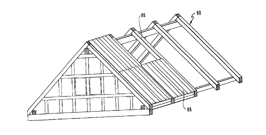
In Figs. 14 and lS a roo~i~g elemen~ 86 Lormed of several
compartment . elements 4, 4', 4'' is represented.
Interconnection of the compartment elements 4, 4~, 4'' is
effected by means of connecting bands 84 applied on the
sheathing layers which are formed by the layers of ~oardç
60, 68. At the lateral edge~ of the co~partment elements
4, 4', in turn, connection pLate~ 22 are provided which
are fastened to front-side square ti~bers As is
particularly shown in Fig. 15, the fron~-side terminzltion
of each compartment element 4 is formed by two squared
t~mbers 86~, 86'' arranged on top of each other (view of
Fig. 15), which jointly for~ a step or a joint. On the
olher front side, two square t~mbers 87'. 87'' are also
~ro~ided in staggered arrangement, with the step on the
CA 0223l350 l998-03-06
_ -23-
~ right-hand fron~ side in Fig. 15 facing up~ard (Fig- 15),
whereas the step on the left-hand front side faces
do~nward, so that upon front-side joining of such
compartmen~ élements 4 an abutting contact section
between t~o adja~ent co~pa:rtment elements 4, 4'- is
created. The stratified structure of compartment elements
4, 4', 4'' may in any desired manner be achie~ed by using
one or several strata S ih accordance with the described
embodiments.
Such roofing elements present the advantage that the
inside of the roof does not requlre panelling any more.
It is only necessary in this case to provide backup
strips for acco~modating the roo~ tiles or some other
type of roofing on the layer of board6 forming the outer
wall
It is, of course, possi~le to form a vapor barrier
on the inner layer of boards in a known manner and apply
a sheet ~hich is open to diffusion on ~he outer layer of
boards to thereby ensure optim~ insulation against
humidity.
As can be seen in Fig. 16, the roofing elements 84
formed in such a ~ay are inserted bet~een adjacent
rafters 8B of a roof structu~e 90.
~etween the boards of the members, insulating
materlal and/or fire breaks (fire resistance beha~ior
acco~ding to ~er~an Industrial Standard DIN 41~2) may be
lnserted.
CA 02231350 1998-03-06
-24-
- In Figs. 17 to 23 another embodiment of a compa~t~ent
elemen~ 4 for use in construction oE a wooden house in
accordance with Fig. 1 is represented.
~ig. 17 shows a cross-sectional view of a like
compartmen~ element 4. Accordingly, this co~partment
element is comprised of a multlplicity of transverse
stra~a 91 extending crosswise to the major surfaces 92 of
the compartment element 4.,The multiplicity of transverse
layers 91 is interconnected by means of suitable
connecting means, such as for example nails, clamps or by
point-shaped adhesive bonding - e.g., by means o~ a lime-
hased adhesive
Each ~ransverse layer 91 consists o~ t~o wooden boards
~hich are hereinafter referred to as layer boards 94, 96.
In ~ig. 18 the production of such a transverse layer 91
including the two layer boards 94, 96 is represented.
Accordingly, a ~ul~iplicity o~ ~oards, only one of3U whi~h is represented in Fig. 18, are sawed from a small-
dimension tLmber of class II or III. Such a small-
dimension timber board 9B thus h~s two ~ark edges 99, 100
which are constituted by the outer surf aces o~ the small-
dimension timber. The major surfaces 102 and the front
surfaces 104 are processed in the cutting step and
possi~ly by a subsequent planing step, whereas of the
CA 02231350 1998-03-06
- bark edges 99, 100 are only stripped of bark and ~ast and
dried (S 99~ residual humidity). In the case of
particularly high standards the bark edge~ may also ~e
processed
This s~all-dimension timber board 98 is sawed apart in
the cent~r along the dash-dotted line in ~ig. 18 whereby
l~) t~o half board halves 94, 96 are obtained. The half board
is then rotated by 18V" around its transverse axis
(crosswise to the longitudinal axis) and placed ~eside
the other half board 96 in such a way that the bark edge
lOO is located opposite the bark edge 99.
Thanks to this rotation of the h~lf board 9~, the
conicity of the small-dimen.sion timber me~ber may be
compen~a~ed, resulting in a nearly square boar~, ~herein
predetermined dimensions may ~e o~served ~y corresponding
~() finishing or levelling of the bark edges 99, lOO. The
element comprised of the half boards 94, 96 sho~n on the
right side in Fig. 18 thus results in ~ transverse layer
91 with the layer boards g4, 96 of the compartment
element ~ in aceordance with Fig. 17. The separating gap
between the two bark edges 99, 100 may optionally be
filled with insulation material. As a rule, ho~ever, a
predetermined distance will be provided here
3U
As a res~lt of the formation of the transverse layer
91 of small-dimension timber ~oards 98 aceording to the
invention, more than 70% of a small-dimension ~im~er log
can be made use of for obtaining such transverse l~yers
3~ 91. Hereby a high-quality compartment element may be
produced at minimum expense of material and production.
CA 02231350 1998-03-06
-26-
~he manner of proceeding in accordance with the inventLon
also permits the use of ~ind~reak and the like timber for
producing high-q~ality construction components. By using
the tran~versé layers 91, panel elements having externa~
dimensions of, e.g., 400 m~ width and up to 9 m length
may be obtained. Different dimensions, such as panels of
2x2 m may, of course, also be obtained, with the
thickne6s of the transverse laye~, depending on the
function, being about 100 to Z50 mm.
JO
In Fig. 19 an example for.the use of this compartment
element 4 of the invention as a ~loor struct~re is
15 represented . ~hat is represented i5 a floorin~ on ~che
ground floor wherein the structure represented in Fig. 19
is applied onto the p~e-fabricated concrete f~oor in~tead
of a floor p~vement. To this end, initially a
m~ltiplicity of joist6 106 are fixed at a par~llel
2~) spacin~ with each other on the concrete floor, and on
them the compartment element 4 according to the invention
or a multiplicity of ~hese compar~ment element~ 4 are
applied in a t~ansverse orientationt ~herein the lateral
edges of the transver~e layer 91 facing away from the
joist~ 106 ~re planed. This are planed layer then forms
the floor for the qro~nd floor. Between the concrete and
the joists 106 a waterproof sheeting may be provided. The
spaced-apart joists 106 allo~ for optimum ~entilation of
the concrete floor.
3~
In Fig. 20 a si~ilar embodimen~ is represented wherein
the compartment element 4 c~nstituting the ceiling
element is applied onto the beam layer 108 of ~he ceiling
6 tructurè.
CA 02231350 1998-03-06
_ -27-
By planing the upper lateral edges of the transvers~
S layer 9l ~ho~n in Fig. 20 it is, in turn, possible to
produce a complete floor ~hich may - optionally
morea~er ~e provided ~ith a cover.
~y omitting one or se~eral làyer boards it is
1~ possible to form a recess l09 for providing sanitary, air
conditioning and~or hea~ing line6 or conduits therein in
the ~ompartment element 4
~ ig. ll shows an embodiment wherein the compart~ent
elements 4, 4', 4'~ accordin~ to the invention are used
for filling the interstices of a hal~-timber framework,
of ~hi~h only the vertical ~embers l0 are visible
Z()
When used as an outer ~all, the separating gap
~etwe~n the bark edges 99, l00 (cf., Fig. 11) may be
filled with mineral fiber. Onto the lo~er major surface
of the half-timber constru~tion shown in Fig. 21
2~ (vertical members l0 and compartment elements 4 to 4"),
~hich forms the lnner ~all I, supporting board~ ll0
arranged at a parallel distance from e~ch other are
applied, with an insulation 111 being provided between
the~. On the supporting boards ll0 transver6e ~trips 112
30 ~ptionally incl~ding fur~her intermediate insulation ll~
are then formed. On these transver~e strips ll~ an inner
wall, for example wooden panelling, gypsum tiles or a
pla6ter base may then be app~ied.
CA 022313~0 1998-03-06
-28- -
~ s a m~tter of fact, the insulation 111 may also in
turn ~e provided on the outer ~all A. This embodiment
will presumably be preferred in practical application
becau~e the dé~r point should be shifted ~o the outside as
far as possîble.
Fig. 22 shows an embodiment wherein the compartment
~0 elements 4, 4", 4' ~ are fastened bet~een members 116.
On this compound construc~ion of members 116 and
compartment ele~ents 4, 4~ and 4~'' a floor cover is
then applied which, in the shown embodiment, may consist
of an footfail sound insulation 118 and any desired floor
struct~re 120 (~ood flooring, clinker, etc.). In this
embodiment the members 116 are formed by the ~nplaned
20 ceiling joists of the ground f loor .
In Fig. 23 a particularly "lux~rious' embodiment o~
an outer wall is rep~esented. This outer wall i~ for~ed
by six compartment elements 4 to 4'' '' according to the
invention executed as a boarding of a corresponding half-
tim~er frame wit~ a double sheathing. Of this half-
timber, in ~urn, only cross-sectlon6 of the vertical
mem~ers 10 are visible.
In accordance ~ith Fig. 23 two wall sectionfi 122,
123, co~prised of the compartment elemen~s 4, ~', 4''',
pr 4''', 4'''', 4''''', are arranged at a parallel distance
CA 022313S0 1998-03-06
_ -29-
f~om each other, wherein ~he outer wall is formed by thecompartment section 122 and the inner ~all is formed by
the compartment 6ection 123. The separating gap ~etween
the two compartment elemen~s 12Z, 123 is executed as an
air gap having a width of approx. 2 to 4 cm.
On the inside as well as on the outside it is again
possible to provLde ~eans for fastening an outer 6heath
or inner layers. ~oreover ,it is again possible to create
space for supply lines and conduits by omitting one or
se~eral layer boards. This variation is comparati~ely
costly, however ~t exhibits excellent thermal and
acoustic insulation properties, makin~ its application
appear sensible in hi~h-quality struc~res ~ith high
requirements to thermal and acousti~ protec~ion-
~he above described compar-tment elements 4 may, of
cour~e, also ~e ~ed for ~illinq out ~on~entional half-
timber constructions and particularly for the renovation
of old buildings.
A particular advantage of the system aecording to
the invention resides in the fact that the b~ilding owner
may contri~ute ~ considera~le amount of prlvate work
e~fort, and that material costs may be reduced tO ~ini~
30 owing ~o the use of small-dimension ti~ber.
Imple~entation o~ the half--timber frame sy~tem of the
invention and of the compartment elements according to
the inven~ion creates a market for the small-dimension
timbers which previously ~e~e practically ~seless and
which can no~ be further processed immediately following
their generation while not ha~ing t~ ~e stored in the
CA 02231350 1998-03-06
_ -30-
forest any longer As a result o~ these ~educed storage
periods, vermin such as the ~ood ~ick or the horntail are
no longer left the time for att~cking the s~all-di~ension
timbers to do away ~ith treating the s~all-dimension
timbers with pesticides.