Note: Descriptions are shown in the official language in which they were submitted.
CA 02231441 1998-03-09
W O 97/11842 PCT~US96/15177
. E~H~CED n~SlnLATION PA~NE~L
CROSS REFERENCE TO RELA~ APPLICATIONS
- This application is related to contemporaneously filed U.S. Patent
5 Application Serial No. 08/533,025, filed Sept,ember 25, 1995, titled "Appliance Door," by
~: Ralph McGrath et al., having attorney docket number 23858/23857, herein incol~o.~Led
by ,ef~.cllce~ and is related to conlelllpo~leously filed U.S. Patent Application Serial No.
- 08/533,024, f~ed S~le~ e 25,1995, titled 'I'ModularTn.~ tinnPanels and Tn~ tedStructures," by R~lph McGrath et al., having ~IllOllley docket number 23845/23855, herein
10 incul~ol~led by refele.lce.
- - - TEC~ICAL FIELD
This invention relates generally to an incnl~tion panel having a frame,
preferably formed of a foamed material, secur~ed in place about its outer periphery.
- E~ACKM~OUND
Thermal inclll~tio~ vacuum panels are known in the art. One such panel is
tlicclosed in U.S. Patent No. 2,768,046. That panel co""~-ises a metal shell or envelope
formed from a pan-shaped metal sheet and a generally fiat metal sheet. The sheets are
welded to one another at their ~butting outer edges. The edges define a flange which
- P.Yt~,nll~c about the outer p~liphel y of the panel. The space between the two sheets is filled
0 with glass fiber inclll~tion~ and the enclosed spaced is ev~ ted to a very low ple~ule.
The p~ ee teaches incc,l~,ol~ g a plurality of his panels into a
refrigerator cabinet. He notes in column 1, lines 45-49 ofthe '046 patent that heat l-,lnsrêr
can occur from one wall or sheet of the panel ~o the other at the abutting edges of the
sheets. In an attempt to ~ e the effect of' such edge leakage, the p~t~ntee teaches
25 providing glass fiber inclll~tion in areas ~ljacçnt to the edges of the panels.
- Vacuum inclll~tion panels having ~.nirollll edge dimensions can be difficult
to m~mlf~ctllre. Dim~ncion~l error may occur during one or more ofthe following
m~mlf~ctllring operations: cutting or otherwis;e fo-l...ng the first and second sections of
the metal envelope, positioning the two sectio~ dj~c~nt to one another and welding their
3 0 abull---g edges tog~ther, and eva~l~tinE~ the envelope.
Since these panels have thin pelipheral fianges, these panels have also been
- found rlifficlllt to handle and transport. Finally, because the panels are formed in part by a
CA 02231441 1998-03-09
W O 97/11842 PCTAJS96/15177metal envelope, it is costly to make available to the end user a large s~lec.tinn of panel
sizes.
Accoldh~gly, there is a need in the art for a thermal in~lllAtion vacuum panel
which has improved thermal pe,ro-,nallce, can be m~mlfActured so as to have u-l-ro-l-- edge
5 ~limP.n~ion~ can be easily m~mlf~ctllred in a number of panel sizes, and permits it to be
easily and safely h~n-lled and L.~.~o-led.
DISCLOSURE OF rNVENTIC)N
These needs are met by the present invention whereby an e.nhAn-~.ed thermal
in~ tion vacuum panel is provided which comp-;ses a vacuum panel provided with an
10 outer peripheral frame, pl~rc;lably formed of a foamed material. The foam frame ~l~h~n~.es
the thermal plopel Lies of the vacuum panel, provides a means to easily vary the outer
rlim~n~ions of the panel without re~uilillg a change in the size of the metal envelope,
~l~p~ves the overall strength of the panel, allows the panel to be h~nrll~d and shipped
more easily and safely, and provides a means for ...~ g uniru-m outer ~lim~n~ione
15 from panel to panel.
In accoldallce with a first aspect ofthe present invention, the ~l~hAI~ced
thermal in~ tion vacuum panel col--~lises a thermal insulation vacuum panel, and a
rl~u.ullg structure secured to at least a portion of the outer periphery of the panel.
Preferably, the L~lung structure extends about ~lbs~ iAlly the entire
20 extent of the outer periphery of the thermal in~ tion panel. However, it is also
co..~ laled that the Ll~.ul.g structure may be secured to only one or more portions of
the outer periphery of the ~a ,llUIll panel. For example, the framing structure may
complise one or more polymeric corner sections which are secured to a like number of
corner portions of the vacuum panel.
In one embodiment, the rl~.ullg structure is formed from a material
sPlected from the group con~i~ting of polyurethane foam material, polystyrene foam
material, and phenolic foam material. However, non-foamed polymeric materials, wood,
or other materials having similar characteristics may be used.
The framing structure may be pit;ru--ned and subsequently adhesively or
30 frictionally secured to the vacuum panel. Alternatively, the L ~--in~, structure may be
foamed or molded about the outer periphery of the panel.
In an alternat*e embodiment, a lei,~l-;ed plastic structure is secured to at
least a portion of an outer edge of the framing structure. The .ei-~--;ed structure may
CA 02231441 1998-03-09
W O 97/11842 PCTAUS96/15177
deLne an ~ttAr~ surface to which~ for example, an inner liner andlor an outer skin of a
~refrigerator çnelosllre are secured either adhesively or via secnring screws which p~cs
IL. ou~ll the ~ ced structure.
The L~ulfil~g structure may have an L-shaped profile in cross section to
5 permit it to mate with an ~dj~cçnt e~.h~ced panel.
In accordance with a second aspect of the present invention, an e .~hAnced
~-thermal jncll1~ti9n ~C~IUl~l panel is provided. The PnhAI~ced panel co~ lises a thermal
incUl~tiQn vacuum panel formed in part by an envelope having an outer pFlil)hely and
polymeric ~i~l~i~ structure secured to at least a portion of the outer periphery of the
:l0 panel envelope.
Accol dill~ly, it is an object of the preseM invention to provide an F nh~n~ed
thermal inclll~tion vacuum panel. It is further an object ofthe present invention to provide
an .jl~hA-~ced thermal insulation ~,at,.lul-- panel ~which COIII~IiSF,S a thermal ;1~ A~;OI~
vacuum panel provided with an outer pelil,hf i ~I frame. It is another object of the present
1~ invention to provide an F .h~ced thermal inculi~tion vacuum panel which co...p. ;Cf ~ a
-~thermal in.cul~tion vacuum panel provided with an outer p~.ipllc.,ll polymeric frarne.
These and other objects of the present invention will be a~l)ar~lll from the
~following description, the ~cco~p~-~ying drawings, and the appended daims.
13RIEF DESCRIPTION OF DRAWINGS
Figure 1 is a pel~c~,live view, partially in cross section, of an çl~h~nced
= thermal inc~ tion vacuum panel formed in accoldal ce with a first embodiment ofthe
present invention;
Figure 2 is a cross-sectional view of an F --hA~red thermal insulation vacuum
panel formed in accGl.lallce with a second embodiment ofthe present invention; and
2'5 Figure 3 is a det~ od cross-section~l view of two F~nh~n~ed thermal
in.cnl~ti~ n vacuum panels formed and joined in accold~lce with a third embodiment ofthe
present invention.
- M[ODES FOR CARRYING OUT THE INVENTION
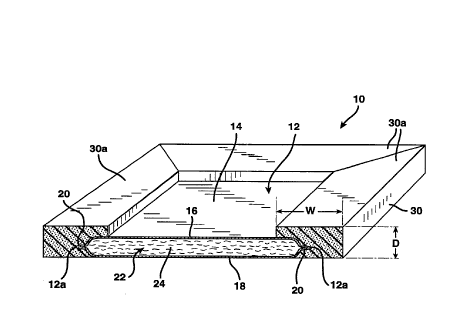
Referring now to Figure 1, there is shown generally at 10 an F~nh~nce(l
3CI thermal inc ~l~tion vacuum panel formed in accol~ lce with the present invention. The
h~ced insulation panel 10 is adapled for use in inc -l~ted a~ ncec such as ovens,
.dishw~Lsht;l~, refri~el~lol~ and Le~,.el~, walk-in coolers, recre~tion~l vehicles, im~ ted
vans or trucks, and reL;gelaled sl~~ g c~ . It is also colllellll~lated that the
,~
CA 02231441 1998-03-09
W O 97/11842 PCTrUS96/15177
~nh~nrjed panel 10 may be used in the constluction Of in~ ted walls and/or ceilings of
pellll~ltlll or temporary structures.
The ~hAI~ced panel 10 colll~-ises a high R-value thermal in,slll~tion vacuum
panel 12, which may be constructed as disclosed in any one of: U.S. patent ap~lic~lion
5 Serial No. 08/271,163, filed July 6, 1994, and entitled "Vacuum Tn~ tion Panel and
Method For ~n~f~ctllrin~"; U.S. patent applic~tion Serial No. 08/405,129, filed
March 16, 1995, and entitled "Vacuum Tn~ tiQn Panel Having Blended Glass Wool Filler
and Method for ~nllf~c~lring''; U.S. patent appliç~tic-n Serial No. 08/405,114, filed
March 16, 1995, and entitled "Vacuum Tnelll~tion Panel Having Pxp~n~led Surface Area
10 Wool Filler and Method for ~mlf~ ..h~"; and U.S. Patent Nos. 5,330,816, 5,286,320,
5,094,899 and 5,090,981, the disclosures of which are incorporated herein by lerert;llce.
The vacuum panel 12 co~ lises a generally rect~n~ r metal shell or
envelope 14 formed from upper and lower ;netal panels 16 and 18. The panels 16 and 18
are welded to one another at their abl~ttin~ outer edge portions. The ~b~tting outer edge
15 portions form a fiange 20 which defines the outer pclilJhely 12a ofthe panel 12. The
space 22 ~t;Lwt;en the two panels 16 and 18 is fflled with thermal inelll~ting media 24, and
the ~nclosed space is ev~cll~ted to a very low pl~ Ul[.
A frarning structure 30 is secured about the outer periphery 12a of the
vacuum panel 12. In the embodiment illustrated in Figure 1, the rl~l~i~ structure 30
20 colllplises discl cle r~ ih~g lllGlllbcl ~ 30a which are adhc~i~ely, frictionally, or oLII~,l wise
r~Lçn~-d or joined to one another and to the outer pcli~h~ly 12a of the vacuum panel 12.
r~,Çel~bly, the Ill~nlbel~ 30a are plcrolllled from a foamed m~t~ri~l, such as apolyulcLhal~e or a polystyrene foam material, and are adhesively applied to the vacuum
panel 12. While not shown in the illustrated embodiment, rcillrol~elllellL m~t~ri~l~, such as
25 glass fibers, may be in~lllded in the foamed m~tf~.ri~l It is also contemplated that the
polymeric material, rather than being pleÇolllled, may be foamed about the outer pe~ )h~.y
12a ofthe vacuum panel 12, or a non-foamed polymeric material may be molded about the
outer pcliphely 12a of the vacuum panel 12. The foamed or molded material may encase
only the outer pc.iphely 12a of the panel 12, in the same manner that mt~.mhers 30a encase
30 the outer periphery 12a ofthe panel 12 as shown in Figure 1. AIL~ llaLi~ly, the foamed or
molded material may cover eeeenti~lly the entire outer surface ofthe panel 12, and material
may be scalloped or otherwise removed from one or both sides of the ~ l~h~nced pa~el 10
to reduce the thicl~ne~ee ofthe ~I.hA~ced panel 10 in its central region.
¦ CA 02231441 1998-03-09
W O 97/11842 PCT~US96/lS177
--- It is further contf~mrlAtf,d that the framing structure 30 may be formed from
dis~i~t;le L~ ~ memhf~-s pr~ --f d from a iiberglass-le..~rolced plastic such as a
polyester-based sheet mokling compound (SMC), a rigid ~mci~l.;ed polymeric m~teri
' su-ch as high-density polyethylene, a coated mletal, wood, etc. Processes for rollll.ng
5 discrete framing ...~I~.be. s from polymeric materials include molding, extrusion, and
pultrusion processes. It is ~dtlition~lly co..lf "~ ted that the framing structure 30 may be
= secured to only one or more portions of the outer pf;.iphf .~ 12a of the vacuum panel 12.
For eY~mple, the L~ulf~l~g structure 30 may cGm~.ise one or more polymeric corner
secl;olls (not shown) which are secured to only corner portions of the V~CUUlll panel.
The width W, depth D, and length of the framing structure 30 can be easily
- varied, such as by cutting or ~rindin~ or by using r~lllfillg app~Lus of a dif~~ l shape
and/or size. Accordi.lgl~, metal envelopes 14 having the same outer dimf n~iom may be
used in the mAmlfAct~-re of ~nllAIlce(l vacuum panels 10 having dilre[e,-l outer ~imensions
This s.~ 1ly reduces the cost of producing panels 10 having di~elellL outer
f..~;on~ since se~ le sets of tooling and other app~a~-ls for rO~ g metal envelopes
oftwo di~lellL sizes are not le~luil~d.
Vacuum ;l.c..l~l;on panels having metal envelopes of l.nirolln edge
;...f ~ ;on~ can be rliffi~llt to mAn~lfAohlre, as ~ ed above in the "BacL~-~Julld"
portion of the present applic~tion This is in ca,llll~l to ~ ng structures 30, which can
20 easily be formed having lmiforrn outer ~ f~ ;ons. Accor~ , with the present
invention, it is possible to econo~ lly ...~ l e f nh~nced thennal inc tion vacuum
panels I0 having uliiro-l-- outer ~l;-n..l-!~;on.c, even though their metal envelopes 14 may
have non-ulliroll~ ;on~ t
As shown in Figure 2, the L~llin~5 structure 30 may have an ~sha~ed or
25 sl~pped profile 30b in cross section to permit ~ c~nt L~nil.g structures 30 of ID~e panels
10 to i,liellllale to f~rilit~te the interco.ll~e~ ofthe ~ cent panels 10. One ofthe
bentLls ofthe framing structure 30 ofthe enh~nced panel 10 is the formability of -he edge
profile for c~lstomrr applir~tion~ Other profile shapes not specifically shown her~in may
I also be employed, inrl~lding interlocking as well as mating profiles.
An ~nh~nr,ed thermal in~ tion vacuum panel 40, formed in accordallce
with a second embodiment of the present invention, will now be described with re~ference
to Figure 3, where like Pl. .~.~."~ are referenced by like numerals. In this embodim~,ent, a
rolced plastic structure 50 is secured about tlhe outer periphery of the L~lling structure
.
=--
CA 02231441 1998-03-09
W O 97/11842 PCT~US96/15177
30. In the embodiment illustrated in Figure 3, the outer p~ ,ipll~,.y of each panel 40 has an
L-shaped or stepped profile and portions oftheir outer peripheries are shown o~,~,.lappil,g
one another. One or more securing screws 60 eYtend through the respective framing
structures 30 and the le"~,-.c"lG,ll plastic structures 50 ofthe A~ljacent panels 40 to
5 co~-l-e~,l the two panels 40 together. In this embodiment, the lcil,rorced structures 50
provide strong layers into which the one or more screws 60 extend and, hence"lll~,lovt;s
r;.~ , rete~ntion over foam alone. Alternatively, the re~rctll~.ll plastic structure 50
may define an ~tt~hment surface to which, for ~y~mp1e~ an inner and an outer wall or
surface (not shown) are secured.
It is further contemrl~ted that a rl~lling structure 30 of e .h~l-ced panels 10
may be formed from a highdensity foamed material, e.g., a 10 poundsMc3 (160 kg/m3)
foamed material, so as to improve its strength and r~s~el~, retention ability.
Accoldill~ly, the present invention provides an ~nh~nced thermal in~nl~tir)n
vacuum panel which co...l.. ;ses a thermal in~ fiQn vacuum panel provided with an outer
15 pe,i~h_,~l frame, prere,al.ly formed of a foamed material. The foam frame ,~h~llces the
thermal pr~,pcll;es of the vacuum panel, provides a means to easily vary the outer
;0115 of the panel without I~lui,ill~ a change in the size of the metal envelope,
improves the overall ~lre.~ ofthe panel, allows the panel to be h~n-lled and shipped
more easily and safely, and provides a means for ~ nin;l~g ulli~llll outer ~l;.,....,~iol.c
20 from panel to panel.
Having desc,;l,ed the invention in detail and by ,~rt;l~nce to the prer~;"~
embo~lim~-nt~ thereof, it will be app~e"l that other modifications and vàl;aliOIls are
possible wilLoul dt;p&, ling from the scope of the invention defined in the appended claims.