Note: Descriptions are shown in the official language in which they were submitted.
CA 0223l607 l998-03-lO
W O 97/13451 PCT~US96/lS766
ACCESS CAl~;l~;~ AND METHOD FOR ~qA~TAINlNG
SEPARATION Bl~ ;~ A FALLOPOSCOPE
AND A TUBAL WALL
RA~R~OUND OF THE lNV ~:N'l'lON
1. Field of the Invention
The present invention relates generally to
endoscopic surgical methods and apparatus. More particularly,
the present invention provides an access catheter having a
distally protruding structure which maintains separation
between a viewing scope and a lumenal wall.
Diseases of the fallopian tubes are a major cause of
infertility and tubal pregnancy. Until recently, diagnosis
and treatment of tubal disease has been hampered by the
difficulty in accessing and imaging the interior of the
fallopian tube. Such difficulties, however, have been largely
overcome by the recent availability of very small guidewires,
catheters, and fiberoptic viewing scopes, usually referred to
as falloposcopes. Using these instruments and systems, a
physician can gain atraumatic access to the interior of the
fallopian tube through a hysteroscope positioned within the
uterus. Such falloposcopic imaging techniques were described
by Kerin et al. in Fertil. Steril., Vol. 54, pp. 390-400
(1990), and in ~. Laparoendoscopic Surg., Vol. 1, pp. 47-56.
Falloposcopic access and imaging techniques are
generally performed as follows. A hysteroscope is positioned
within the uterus and an irrigating solution is introduced to
distend the uterus and permit video monitoring. A very small
guidewire is then introduced through the hysteroscope and
advanced past the ostium and into the fallopian tube. The
guidewire will continue to be advanced until it approaches the
distal fimbria. A small tubular access catheter may then be
advanced through the hysteroscope and over the guidewire into
CA 02231607 1998-03-10
W O 97/13451 PCT~US96/15766
the fallopian tube, again preferably approaching the distal
fimbria. After removing the guidewire, the falloposcope
(which is a small diameter fiberoptic bundling including both
imaging and illumination fibers in a single shaft) is advanced
until its distal end reaches the distal end of the access
catheter. Imaging may then be performed in a retrograde
manner with the falloposcope and access catheter being drawn
outwardly together through the fallopian tube while producing
an image on the associated video monitor. The lumen of the
tubular access catheter will also provide an access path for
devices, such as drug delivery catheters, small instruments,
and the like, for treatment of tubal lumen disease.
While such retrograde falloposcopic imaging
techniques represent a significant improvement, they still
suffer from certain limitations. In particular, falloposcopes
having both illumination and imaging fiberoptics require a
i n; ~m separation between the imaging lens at the end of the
fiberoptic bundles and the tissue to be imaged.
Unfortunately, the narrowly confined lumen of the fallopian
tube contracts soon after the access catheter has been
withdrawn Hence, the tubal wall often collapses in on the
withdrawing falloposcope during retrograde imaging, intruding
upon the required imaging separation. As the tubal wall
tissues come in close proximity with the imaging and
illumination fiberoptics, excessive illumination light is
reflected back to the imaging system, causing a partial or
total "white-out" of the viewing monitor. These white-outs
are a common and undesirable limitation on the effectiveness
of retrograde imaging of the fallopian tube and other narrow
body lumens.
It would therefore be desirable to provide improved
methods and systems for imaging fallopian tubes and other
narrow body lumens. It would be particularly desirable to
provide improved access catheters and methods for their use
which would reduce the incidence of white-out associated with
the fallopian tubal wall approaching too close to the optical
viewing scope. It would further be desirable if such improved
methods and devices were compatible with and able to enhance
CA 0223l607 l998-03-lO
W O 97/13451 PCTrUS96/15766
the effectiveness of retrograde tubal imaging systems and
methods.
It would also be desirable to provide improved
imaging access methods, devices, and systems for use in the
fallopian tubes and other body lumens. It would be
particularly advantageous to provide simplified, atraumatic
imaging methods and systems which would reduce the time and
complexity of known fallopian tube accessing and imaging
techniques, and which would provide reliable, high quality
lO images of tubal walls to assist in the diagnosis and therapy
of tubal disease.
2. DescriPtion of the Backqround Art
Kerin et al., Fertil. Steril., Vol. 54, pp. 390-400
(l990), and in .J. Laparoendoscopic Surg., Vol. 1, pp. 47-56,
have been described above. U.S. Patent No. 4,793,326
describes an industrial endoscope having an elongated arm
member to facilitate advancing separate illumination and
observation windows past the abrupt steps of piping elbow
joints. U.S. Patent No. 4,717,387 describes an intercardiac
catheter having a distal balloon for positioning the catheter
with respect to a body surface to be viewed through an optical
scope. U.S. Patent No. 5,263,982 describes an endoscopic
catheter having a laterally offset movable guidewire.
U.S. Patent Nos. 5,047,848 and 4,825,259 disclose
baroscope having specialized distal tip gauges which permit
optical measurements of imaged features. U.S. Patent No.
4,608,965 discloses an endoscopic sheath having a Malecott--
type structure for anchoring the scope in a body cavity.
U.S. Patent No. 5,358,496 is representative of
numerous instruments intended to be inserted through
endoscopes. U.S. Patent Nos. 3,866,601; 4,306,566; 4,350,147;
4,846,812; 5,099,827; 5,263,928; 5,279,596; 5,306,261;
5,307,814; 5,308,342; 5,385,152; are also relevant.
An exemplary falloposcopic imaging system is
described in co-pending application Serial No. 08/027,475,
filed March 7, 1994, the full disclosure of which is
incorporated herein by reference.
CA 02231607 1998-03-10
W O 97/13451 PCTrUS96/lS766
SUN~L~RY OF THE lNV~:N-llON
In a first aspect, the present invention provides a
method for viewing a lumenal wall of a narrow body lumen. The
method of the present invention comprises introducing a
catheter within a body lumen and positioning an optical
viewing scope within a lumen of the catheter so that a distal
end of the scope is at a scope viewing position adjacent to a
distal end of the catheter. A spacing structure is positioned
between the lumenal wall and the distal end of the scope
maintains separation between the lumen wall and the scope.
The lumenal wall is imaged through the scope while the spacing
structure maintains separation between the distal end of the
scope and the lumenal wall. This separation helps prevent
imaging white-out conditions which might otherwise occur when
the optical viewing scope and body lumen wall are in close
proximity. Although the spacing structure will typically
appear in the viewing monitor, blocking some portion of the
lumen wall from imaging, the image quality and availability
are substantially enhanced. Preferably, the catheter is
advanced distally of a target region of the body lumen during
the introducing step, and the catheter and scope are
proximally withdrawn while imaging through the distally
oriented scope. This is generally referred to as "retrograde
imaging."
In some embodiments, the imaging step comprises
viewing the lumen wall at least in part through a cage
disposed over the distal end of the scope. Alternatively, the
spacing structure may comprise a guidewire which extends
distally from the catheter, which guidewire may also be
rotated during introduction of the catheter to maneuver the
catheter through a body lumen system. Alternatively, the
spacing structure may comprise a wire loop extending distally
from the catheter body. Such a wire loop may be expanded by
advancing a proximal length of the wire relative to the
proximal end of the catheter. In this way, the size of the
loop can be adjusted maintain separation between the body
lumen wall and the optical viewing position.
CA 02231607 1998-03-10
W O 97/134Sl PCT~US96/15766
In another aspect, the present invention provides an
improved method for viewing a target region of a fallopian
tube. The method is of the type including transcervically
~ accessing the fallopian tube with the catheter and inserting
an optical viewing scope within a lumen of the catheter so
- that distal ends of the scope and catheter are adjacent to
each other, and then retrograde imaging the fallopian tube by
withdrawing the scope and catheter together. The improvement
comprises promoting axial alignment between the tubal wall and
the distal end of the scope with a structure extending
distally from the distal end of the catheter. Axial alignment
between the distal end of the scope and the tubal wall will
optionally comprise axially rotating the catheter to engage
the structure against the tubal wall, where the structure is
unsymmetrical about an axis of the catheter lumen.
Advantageously, such an unsymmetrical spacing structure can be
used to selectively engage only that portion of the tubal wall
which is necessary to avoid a white-out. The unsymmetrical
spacing structure further avoids blocking of the imaging view
where not required to prevent intrusion of the tubal wall
toward the viewing scope.
In another aspect, the present invention provides a
catheter for viewing a wall of a narrow body lumen, the
catheter for use in combination with an optical viewing scope
of the type including both illumination fibers and viewing
fibers. The catheter comprises an elongate tubular body
having a proximal end, a distal end and a central lumen
therebetween. The lumen slidably receives the shaft of the
scope to a scope viewing position adjacent to the distal end
of the body. Additionally, a spacing structure extends
distally from the distal end, usually being fixed or coupled
thereto, so as to separate the scope viewing position from the
lumen wall. Advantageously, the catheter of the present
invention need only include a single axial lumen, thereby
; n; ; zing its cross-sectional size. Preferably, the spacing
structure is affixed with a coupler ring which fittingly
engages the body, the coupler ring ideally being disposed
within the body lumen and having an outer diameter which is
CA 02231607 1998-03-lO
W O 97/13451 PCT~US96/15766
larger than a relaxed lumen diameter. In some embodiments,
the spacing structure comprises a cage disposed over the scope
viewing position. The cage may comprise a distal extension of
the body having a plurality of viewing slots, or may
alternatively comprise a separate structure attached to the
distal end of the catheter.
In some embodiments of the catheter of the present
invention, the spacing structure comprises a guidewire which
extends distally of the body, typically being cantilevered
from the distal end of the catheter at the edge of a distal
lumen opening. Ideally, the guidewire comprises a coiled
distal section and an uncoiled section between the catheter
and coil. This provides an increasing distal flexibility
comparable to that of distally tapering guidewires, but with a
decrease in proximal guidewire cross-section. The flexibility
of the guidewire is ideally similar to tapered guidewires sold
under the tradenames "Traveler" and "Robust" by Conceptus,
Inc. of San Carlos, California, the present assignee. The
guidewire may thus find use in maneuvering the catheter
through the body lumen, and may also allow the catheter to be
advanced while "antigrade" imaging through a scope at the
scope viewing position. Such antigrade imaging will
potentially provide a means for directing the catheter
distally, and also provide a simultaneous image of the tubal
wall. Alternatively, the spacing structure may comprise an
expandable distal loop actuable by advancing a proximal
portion or extension of the loop relative to the proximal end
of the body. This provides a controllable separation between
the lumen wall and the scope viewing position to overcome
white-out conditions as they are encountered along the body
lumen. As a further alternative, the spacing structure
comprises one or more diagonal tips extending from the distal
end of the body.
In yet another aspect, the present invention
provides a method for viewing a luminal wall of a narrow body
lumen, the method comprising introducing a catheter into the
body lumen, the catheter having an access lumen and a distal
spacing structure. An optical viewing scope is positioned
CA 02231607 1998-03-10
W O 97/134Sl PCT~US96/15766
through the access lumen of the catheter. The scope images
the luminal wall through the spacing structure while the
spacing structure maintains separation between the distal end
of the scope and the luminal wall. Generally, imaging is
performed through openings defined by discreet structural
elements of the spacing structure, the spacing structure
typically comprising a perforate cage. Ideally, the cage
flexes to accommodate bends in the body lumen, and includes a
large, rounded! distally oriented surface that promotes
tracking of the cage and access catheter along the body lumen
when the catheter advances axially therein. The cage
optionally helps to center the scope within the body lumen,
and may also distend the body lumen to facilitate viewing of
the inner surface of the luminal wall. Advantageously, such a
caged structure will allow safe and effective antigrade
imaging of narrow body lumens (such as the fallopian tube) by
carefully controlling the relative positions of the scope and
portion of the surrounding luminal wall.
In yet another aspect, the present invention
provides a catheter for viewing a wall of a narrow body lumen.
The catheter of the present invention will be used in
combination with an optical viewing scope, the catheter
comprising an elongated tubular body having a proximal end, a
distal end, and a lumen therebetween. A spacing structure
with a plurality of cage elements extends distally from the
distal end of the tubular body, the spacing structure adapted
to maintain separation between the scope and the surrounding
luminal wall when the scope images the body lumen between the
cage elements. Preferably, the spacing structure is adapted
to track along the body lumen when axially advanced therein,
typically having at least an axial portion which is flexible,
and a tracking tip which provides a large, rounded distally
oriented surface. Ideally, the axial elements comprise a
super-elastic shape memory alloy such as Nitinol~.
In yet another aspect, the present invention
provides a fallopian tube viewing system for imaging a tubal
wall of the fallopian tube, the viewing system comprising a
falloposcope having a proximal end, a distal end, and an axis
CA 0223l607 l998-03-lO
W O 97/1~451 8 PCTrUS96/15766
therebetween. The access catheter has an elongate tubular
body with a proximal end, a distal end, a lumen therebetween
which slidably receives the falloposcope. A flexible
separation structure extends distally from the distal end of
the body to maintain separation between the scope and the
surrounding tubal wall when the scope is disposed within the
lumen of the access catheter, when the scope and catheter are
disposed within the fallopian tube, and when the body lumen is
imaged through the scope through the separation structure.
In yet another aspect, the present invention
provides a method for manufacturing a caged access catheter,
the method comprising attaching a plurality of flexible
elongate cage elements to each other at a junction. A
tracking tip is formed at the junction, the tracking tip
having a rounded surface which is larger than the combined
cross-sections of the cage elements. The cage elements are
affixed about a lumen of a tubular body so that the elongate
elements extend distally from the tubular body.
BRIEF DESCRIPTION OF THE DRAWINGS
Fig. 1 illustrates a prior art access catheter and
optical viewing scope used for retrograde imaging of a
fallopian tube.
Fig. 2 is a detail view showing the distal ends of
the access catheter and optical viewing scope of Fig. 1 in
close proximity to the tubal wall, which is typical of the
white-out conditions encountered when using the access
catheters of the prior art.
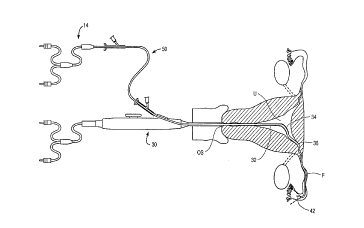
Fig. 3 illustrates a preferred combination of a
hysteroscope, access catheter, and falloposcope for use in
imaging a fallopian tube, according to the principles of the
present invention.
Fig. 4 illustrates a preferred method for supporting
the proximal end of the hysteroscope according to the method
of the present invention, wherein the proximal end is
immobilized by a support structure attached to a table.
Fig. 5 illustrates a falloposcope which is separated
from a tubal wall by an access catheter having a distal cage
CA 0223l607 l998-03-lO
W O 97/13451 9 PCTrUS96/15766
structure, according to the principles of the present
invention.
Fig. 6 illustrates an alternative cage structure
~ formed by cutting axial viewing slots in a distal extension of
the catheter body.
~ Fig. 7 illustrates a falloposcope which is separated
from a fallopian tube wall by an access catheter having a
distally protruding diagonal tip, in accordance with the
principles of the present invention.
Fig. 8 illustrates an access catheter having a
plurality of diagonal tips extending from the distal end of
the catheter body, in accordance with the principles of the
present invention.
Figs. 9A and B illustrate an access catheter having
a plurality of side openings and a central lumen opening which
provide a balanced flow path for irrigation fluid to maintain
separation between the falloposcope and the tubal wall.
Figs. lOA, B and C illustrate a preferred access
catheter having a distal guidewire for maintaining axial
alignment and separation between a falloposcope and a
surrounding fallopian tube.
Figs. llA, B, C, and D illustrate access catheters
having a guidewire which extends from the distal end of the
catheter body to form a distal loop, which distal loop can be
expanded by axially advancing a proximal extension of the
guidewire, in accordance with the principles of the present
invention.
Figs. 12A and B illustrate an access catheter having
an extended diagonal tip formed by joining different tubes and
cutting the joined tubes along a curve.
Figs. 13-13D illustrate a preferred embodiment of a
caged access catheter having flexible cage elements and a
tracking tip with a rounded distal surface to improve
trackability, particularly during antigrade imaging of
tortuous narrow body lumens such as the fallopian tubes.
Figs. 14A-H illustrate a variety of alternative
flexible caged access catheters according to the principles of
the present invention.
CA 02231607 1998-03-10
W O 97/13451 PCT~US96/lS766
Figs. 15A and B illustrate alternative methods for
securely attaching a tracking tip body having a rounded
surface at the distal end of a flexible cage by winding sub-
coils over the cage elements, and then soldering an outer coil
over the distal end so that the solder forms the distal
rounded surface.
Fig. 16 illustrates an alternative tracking tip
formed by melting the distal ends of the flexible cage
elements using thermocouple forming techniques.
Fig. 17 illustrates an alternative distal cage
having a proximal collar to facilitate attachment of the cage
to the catheter body.
Figs. 18A and B illustrate methods for producing a
caged access catheter in which the cage elements are joined to
each other prior to attachment to the catheter body, either
before or after the caged elements are bent to their final
shape.
Fig. l9A illustrates an alternative access catheter
according to the present invention in which a toroidal balloon
disposed at the distal end of the catheter maintains
separation between the luminal wall and the distal end of the
scope.
Fig. l9B illustrates an alternative catheter
according to the principles of the present invention in which
an optically transparent balloon maintains separation between
the scope and the luminal wall while the luminal wall is
imaged through the balloon membrane.
Figs. 20-22A illustrate the enhanced trackability
provided by the distal rounded surface and the axially
flexible cage of the preferred access catheter of Fig. 13.
Fig. 23 illustrates a flexible access catheter
similar to the preferred access catheter of Fig. 13 in which
the cage is bent to function as a steerable guidewire, and
also illustrates axial manipulation of the scope within the
cage to provide enhanced imaging flexibility, according to the
principles of the present invention.
CA 0223l607 l998-03-lO
W O 97/13451 PCT~US96/15766
11
DETATTT!n DESCRIPTION OF THE SPECIFIC EMBODIMENTS
The present invention provides systems, devices, and
methods for accessing and imaging narrow body lumens for the
diagnosis and treatment of lumenal disease. The techniques
and apparatus of the present invention will generally make use
of small optical viewing scopes having both imaging and
illumination capabilities, and will maintain separation
between the scopes and the lumenal wall to enhance image
quality and reliability. In some embodiments, the structures
and methods will also help align the lumenal wall relative to
the scope for effective viewing.
The present invention will have applications for
imaging of the vasculature (particularly of the coronary
arteries), the ureter, and spinal column. The most immediate
application of the present invention, however, will be in
trancervical imaging and accessing of the fallopian tubes.
Advantageously, the methods and devices of the present
invention can promote effective antigrade imaging of these
narrow, delicate, tortuous body lumens, allowing positioning
to be optically directed, and avoiding the time consuming
guidewire positioning and replacement steps of known
retrograde tubal access methods.
Referring to Figs. 1 and 2, a prior art retrograde
fallopian tube viewing system 10 includes an access catheter
12 and a falloposcope 14. Prior art viewing system 10 is
inserted to the distal portion of a fallopian tube 16, and is
withdrawn proximally as indicated to provide retrograde
imaging. Fallopian tube 16 is quite narrow and tortuous, and
the tubal wall is highly flexible. Hence, as prior art
imaging system 10 is withdrawn proximally, the tubal wall is
distended by the access cover 12, and then collapses down to
its relaxed shape after a distal end 18 of the access catheter
has passed. As optimal imaging occurs when the distal end of
the falloposcope is substantially aligned with the distal end
of the access catheter, the tubal wall often comes into close
proximity with distal end of falloposcope 20.
Falloposcope 14 generally includes two distinct
types of optical fibers. The first group of optical fibers is
CA 02231607 1998-03-lO
W O 97/13451 PCT~US96/15766 12
used to transmit light to the distal end of falloposcope 20 to
provide illumination for optical viewing. The second type of
optical fiber, often comprising a single optical fiber bundle
called a "coherent image fiber optic bundle," transmits an
optical image from a lens at a distal end of falloposcope 20
to a proximal imaging apparatus. The image itself comprises
the illumination light from the illumination fibers which is
reflected by objects located within a field of view 22 of
distal end of falloposcope 20. As the tubal wall comes into
close proximity with both the illumination and optical viewing
fibers at the distal end of the falloposcope, the imaging
apparatus is unable to produce a coherent picture, and a
partial or a total white-out occurs on the viewing monitor.
A particularly preferred method and apparatus for
performing hysteroscopic and falloposcopic procedures,
including retrograde imaging, is described in co-pending U.S.
Patent Application Serial No. 08/207,475, filed March 7, 1994,
the full disclosure of which is herein incorporated by
reference. As more fully explained in that application, a
preferred method for performing falloposcopic procedures makes
use of a hysteroscopic viewing scope 30 having a working shaft
32 with a deflectable distal end 34, as shown in Figs. 3 and
4. Working shaft 32 is introduced to the uterus U, ideally
using an adjustable support system 40. Deflectable distal end
34 is directed toward an ostium 36 of fallopian tube F. The
uterus will be distended by introduction of irrigation fluid
so that a guidewire may be directed into the fallopian tube
using visualization through hysteroscope 30. Optionally, the
guidewire 42 is disposed at the distal end of a catheter, as
described hereinbelow. Alternatively, a conventional
guidewire is first introduced to the fallopian tube, so that
an access catheter 50 may be advanced over the guidewire in a
conventional manner. Where such a conventional guidewire is
used, it must generally be removed from a central lumen of
positioned access catheter 50 to make room for falloposcope
14.
In order to further simplify the falloposcopic
procedures of the present invention, support structure 40
CA 0223l607 l998-03-lO
W O 97/13451 PCT~US96/15766 13
immobilizes the viewing scope 30 on a table T or other
surface, once the scope has been properly positioned in the
uterus. Support structure 40 includes a plurality of arms 62
and joints 64 which are designed to freely articulate so that
a support base 66 at a distal end of support structure 40 can
be moved freely in space until locked into position.
Preferably, the support structure is firmly secured to a table
leg L. Such systems commercially available from suppliers
such as Lino Manfrotto & Company.
Referring now to Fig. 5, a caged access catheter 70
slidably receives falloposcope 14 to a scope viewing position
at which falloposcope distal end 20 is adjacent to a distal
end of the catheter 72. A distal cage structure 74 surrounds
distal scope end 20 to prevent the tubal wall of fallopian
tube 16 from coming into such close proximity with the distal
end of the scope that a white-out occurs.
Distal cage 74 separates the tubal wall from the
scope viewing position by any of at least three different
mechanisms. First, cage 74 prevents the tubal wall from
collapsing immediately after catheter distal end 72 has
passed, restraining the tubal wall in its distended position,
thereby preventing encroachment of the tubal wall toward the
scope. Second, distal cage 74 may reposition the entire
distal portion of access catheter 70 away from the tubal wall
to provide the necessary separation. Finally, distal cage 74
promotes axial alignment of catheter distal end 72 with the
fallopian tube by providing an elongated distal moment arm
through which the access catheter and tubal wall engage each
other. This also promotes alignment between the falloposcope
field of view 22 relative to the orientation of the local
fallopian tube axis.
Referring now to Fig. 6, an alternative caged access
catheter 80 is formed with a simplified cage 82. Simplified
cage 82 comprises a continuation of the catheter body beyond
catheter distal end 84, in which a plurality of viewing slots
86 have been cut. Both caged embodiments of the present
access catheter generally provide substantially axisymmetric
viewing through an open distal end of the caged structure and
CA 02231607 1998-03-10
W O 97/13451 PCT~US96/lS766 14
through viewing slots 86, or the analogous gaps between the
cage structural elements. Rotation of such caged access
catheters is generally not necessary to insure separation
between the falloposcope and tubal wall, but will allow
viewing of tubal wall elements which would otherwise be
blocked during at least a portion of the scan.
Referring now to Fig. 7, a diagonal tip access
catheter according to the present invention comprises a
diagonal tip 92 extending distally from catheter distal end
94. It can be seen that diagonal catheter 90 must be rotated
so as to engage tubal wall 16 with diagonal tip 92. It can
also be seen that the field of view 22 is clear in much of the
area where distal structure is not required to engage the
tubal wall. The angle of diagonal tip 92 will typically be in
the range between 45~ and 80~ from normal, and need not be
constant nor extend the entire catheter width. A multiple
angle access catheter 100 reduces the need for rotating the
catheter, as seen in Fig. 8.
Referring now to Figs. 9A and B, a fluid separating
catheter 110 comprises a plurality of radial distal passages
adjacent to the catheter distal tip 116. Radial passages 112
direct clear flush solution against the tubal wall of
fallopian tube 16 to promote separation between falloposcope
14 and the tubal wall. Flush solution also flows out the
distal tip 116 of fluid catheter 110 around falloposcope 14,
thereby promoting separation between the distal end of the
falloposcope and the tubal wall. The fluidic paths
represented by the radial passages 112, are preferably
balanced by varying the sizes of the radial passages relative
to the open gap 114 between the catheter and falloposcope at
the distal end.
A fixed distal guidewire access catheter 120 will be
described with reference to Figs. lOA through C. Guidewire
catheter 120 comprises a distal guidewire 122 extending
distally from a distal end of the catheter body 124, typically
by a distance from 0.5 to 5 cm, ideally being 1 to 3 cm long
and less than 0.02" in diameter. The catheter body includes a
distal portion 126, typically being between 2.2 and 3.0 F, and
=
CA 0223l607 l998-03-lO
W O 97/13451 PCTrUS96/15766
first and second enlarged portions 128, 130. First and second
enlarged portions 128, 130 reduce the pressure required for
the introduction of clear flush around the falloposcope 14, as
is more fully explained in co-pending U.S. Patent Application
Serial No. 08/207,475, the full disclosure of which has
previously been incorporated by reference. A Touhy-Borst
valve 132 is provided near the proximal end of the catheter to
seal the proximal end and also allow access for falloposcope
14. An irrigation port 134 is also provided.
A particularly advantageous structure for supporting
distal guidewire 122 comprises a distal ring coupler 125 which
is fittingly inserted within distal portion 126 of guidewire
catheter 120. The ring coupler provides effective support for
the guidewire, but does not increase the proximal size or
stiffness of the catheter body, and also maintains a smooth
outer surface. Typically, the coupler ring and guidewire will
comprise stainless steel, platinum, or a shape memory alloy
such as Nitinol~, or the like. The guidewire will typically
be coiled, but will ideally include an uncoiled portion
extending to internal coupler ring 125, thereby minimizing the
blockage of the catheter lumen.
Distal guidewire 122 is offset distally at an edge
of guidewire catheter 120, and thereby allows the rotational
engagement of the tubal wall described above regarding Fig. 7.
Advantageously, the guidewire blocks the smallest possible
imaging area, and also provides increased functionality for
the catheter by allowing the catheter to be self-guided during
introduction. Furthermore, the central lumen is not occupied
by a conventional guidewire during advancement of the catheter
into the fallopian tube, thereby providing the attending
surgeon the option of advancing the falloposcope to the
viewing position of guidewire catheter 120 to visually direct
catheter advancement.
Referring now to Figs. llA through D, a looped
guidewire access catheter 140 generally comprises a guidewire
which extends distally from a distal catheter body end 143,
the guidewire forming a distal loop 142. A proximal extension
144 of the guidewire runs along the length of the catheter
CA 0223l607 l998-03-lO
W O 97/13451 PCT~US96/15766 16
body, allowing the distal loop to be manipulated by axially
advancing and retracting extension 144 relative to the
proximal end of the catheter body. As shown in Figs. llB
through D, extension 144 may be disposed within the lumen of
the catheter body, or may alternatively pass through guides
146 on the outer surface of the catheter. Alternatively, a
separate lumen may be included in the catheter body, although
this will require an increase in the cross-sectional size of
the catheter. The guidewire may be attached to the distal end
of the tip using coupler ring 125 (Fig. lOC), or may
alternatively extend from a distal outer ring 148, or from the
catheter lumen wall itself.
Advantageously, distal loop 142 provides an active
mechanism for the surgeon to control the separation between
the tubal wall and the falloposcope. By advancing extension
144 distally only when a white-out condition occurs, the
distance between the tubal wall and the scope may be varied
without having to move the scope itself. The guidewire loop
may further be retracted when not in use, and may also be
biased to assume a particular distal shape, as seen in Fig.
llC.
Figs. 12A and B illustrate a particularly
advantageous access catheter 150 which is formed by joining an
intermediate tube 151 and an end tube 152 to catheter body
tubing 153. The tubes may be adhesively bonded, or preferably
melted together. The diameter of the tubing increases toward
the distal end 154. A curved cut forms an extended diagonal
tip 157. Proper selection of tubing material, together with
careful shaping of the extended tip 157, provides control over
the flexibility of the distal structure. Clearly, the tip
shape may comprise a smooth curve or a series of angles, and
any number of tubing sections may be joined, within the scope
of the present invention. Advantageously, extended diagonal
tip 157 provides the functionality of a distal guidewire, but
with an easily fabricated, uninterrupted structure.
Referring now to Fig. 13, a preferred embodiment of
a caged access catheter 200 has a proximal end 202 and a
distal end 204. A catheter body 206 extends distally from
CA 02231607 1998-03-10
W O 97/13451 PCT~US96/15766 17
near the proximal end to a tracking cage 208. A valve
assembly 210 at the proximal end of catheter body 206 provides
sealing, and will generally include an irrigation port 212.
The valve assembly will typically be attached using a strain
relief coupling 214, as is generally known in the art.
- The catheter body 206 will include a relatively
large diameter proximal portion 216 and a smaller diameter
distal portion 218, the distal portion preferably being at
- least about 3 inches long. Catheter lumen 220 will typically
range between about 0.015 and 0.05 inches in diameter, often
being smaller in the distal portion 218 than in the proximal
portion, as described above. The catheter body will generally
have an outer diameter of between about 0.020 and 0.075
inches, and a total length of between about 8.0 and 25.0
inches. The smaller diameter distal portion will preferably
be between about 4.0 and 7.0 inches in length.
Cage 208 comprises a plurality of axially oriented
cage elements 222 which extend distally from the distal end of
catheter body 206. Preferably, cage elements 222 have both
high strength and high flexibility, ideally comprising a shape
memory alloy such as Nitinol~ with super-elastic properties
when at body temperature. A tracking tip 224 is disposed at
the distal ends of the cage members, the tracking tip having a
relatively large rounded distal surface. The tracking tip may
be formed from a wide variety of polymer or metallic
materials, preferably comprising a shape memory alloy,
urethane, adhesive, solder, or the like. In many embodiments,
the cage elements are affixed together at the tracking tip to
maintain the structural integrity of the cage.
Referring now to Fig. 13A, the cage elements are
generally disposed radially about the distal end of catheter
body 206. Preferably, there are at least four cage elements
surrounding the scope, so that the cage effectively maintains
separation between the distal end of the scope and a
surrounding tubal wall 226 even when the tubal wall protrudes
somewhat inward between cage elements. The use of four or
more cage elements also minimizes the effect of any rotational
misalignment or deformation of the cage elements. In other
CA 0223l607 l998-03-lO
W O 97/13451 PCT~US96/15766 18
words, if two adjacent cage elements are at roughly 90~ as
shown, each can spread by 15~ and the adjacent cage elements
will still be separated by only 120~, generally close enough
to prevent the lumenal wall from encroaching too close to the
scope. Hence, even when the cage is distorted, as when
navigating a tight luminal curve, a cage of four or more axial
elements can generally avoid white-out.
Referring now to Fig. 13B, cage elements 222 extend
proximally along catheter body 206, typically being affixed
around the catheter body by heat-shrink tubing or the like.
In some embodiments, the cage elements may extend distally
from the catheter body to tracking tip 224, and then bend back
to the catheter body. Such bent caged elements help maintain
the structural integrity of the cage at the tracking tip, and
are particularly beneficial for use with tracking tips formed
of polymer materials such as urethane. A tracking tip making
use of bent cage elements is illustrated in Fig. 13C.
Referring now to Fig. 13D, cage 208 preferably
,includes a highly flexible distal portion 22 8 of relatively
small cross-section, and a radially outward flared proximal
- portion 230 adjacent catheter body 206. The flared portion
helps to center the scope within larger portions of the body
lumen, and perhaps more importantly, the flare prevents the
luminal wall from encroaching on the scope when the cage
flexes to traverse bends in the body lumen. The distal
portion of the flare may also help to hold a portion of the
luminal wall (in particular, that portion which is at the
proper focal distance and within the field of view from scope)
at a steeper angle, thereby improving the image of the tissue
surface. The cage will typically extend distally from the
catheter body by a total of between about 0.5 and 1.5
centimeters.
Flared portion 230 will typically protrude radially
beyond the adjacent catheter body, typically extending between
about 0.02 and 0.05 inches radially beyond the adjacent
portions of the cage. The cage ideally tapers radially inward
distally from the flared portion to the tracking tip, the
narrow cross-section helping to enhance the axial flexibility
CA 02231607 1998-03-10
W O 97113451 PCT~US96/15766
19
of the cage structure. The tracking tip also protrudes
radially beyond the adjacent cage cross-section so that the
tracking tip will slide over irregularities in the lumenal
surface, but is generally no larger than the distal end of
catheter body 206.
A variety of alternative cage structures are
illustrated in Figs. 14A-H. Optionally, a coil 232 may extend
distally to act as a conventional guidewire tip. In some
embodiments, an intermediate body 234 may help minimize
separation and maintain structural integrity of the cage
surrounding the scope. Cage elements 222 may optionally
define a rounded distal bend 236, thereby providing an
atraumatic distal surface without having a separate tracking
tip body. Alternatively, a pointed cage end 238 defined by
sharp bends in cage elements 222 may be advantageous for
certain applications. In summary, the distal tip can be
formed to the specific geometry desired, and the cage may
include additional axially oriented or transverse cage
elements.
Similarly, a wide variety of rounded tip bodies may
be used as tracking tips. However, it should be recognized
that as the number of cage elements increases, the discreet
number of areas blocked from view when imaging the luminal
walls will also increase, imaging being performed through the
openings defined between cage elements. While a relatively
large tracking tip may block some portion of the image, the
tip itself may be outside the field of view from the scope
when used within tortuous narrow body lumens such as the
fallopian tubes, and may be outside the focal range of the
scope when it is not otherwise blocked. In other embodiments,
it may be advantageous to have the tracking tip within the
image provided by the scope, so that axial advancement of the
catheter may be directed while viewing the proximal portion of
the tracking tip body.
Referring now to Figs. 15A and B, the strength of
the junction formed at the tracking tip may be enhanced by
winding sub-coils 250 around some or all of the cage element
distal ends, particularly when the tracking tip comprises
CA 0223l607 l998-03-lO
W O 97/13451 PCT~US96/15766
solder. Optionally, the sub-coils are then inserted within an
outer coil 262. This outer coil facilitates the formation of
a rounded distal tracking tip surface 264 from the molten
metal. Alternatively, a single sub-coil 260 may be wound
around a plurality of the ends of a bent cage structure
adjacent the distal bend 266, ideally around three of the four
ends as illustrated in Fig. 17B. Such coils and sub-coils
generally comprise small ribbons of a high strength metal such
as platinum.
Referring now to Fig. 16, a particularly
advantageous distal tracking tip 270 may be formed and
attached by melting the material of the cage elements
themselves. Conveniently, techniques commonly used for
forming thermocouples have been found to form such a
structure. Thermocouples are often produced by forming an
electrical arc between a first surface and the ends of a
plurality of wires, the arc heating the wire ends to form a
molten ball. Thermocouple welders for production of these
structures are commercially available from the Unitek Miyachi
Corp. of Monrovia, California. It has been found that by
clamping a plurality of metallic cage elements in the desired
configuration, such a thermocouple welder is capable of
producing an integral tracking tip at the ends of all of the
cage elements in a single step, even where the cage elements
comprise a shape memory alloy.
Referring now to Fig. 17, it may be advantageous to
join the proximal ends of cage elements 222 to a ring 272 as
illustrated. Preferably, ring 272 is affixed to the catheter
body by laminating the ring between an inner catheter 274 and
a shrink wrap tubing 276. These inner and outer layers are
preferably bonded together distally of ring 172. Nonetheless,
the length of the catheter body which is axially stiffened by
the ring of the cage may be less than the embodiment of Fig.
13, in which each of the cage elements are bonded individually
to the catheter body. Such individual cage element/catheter
body bonds (as shown in Fig. 13) typically include an overlap
of between about 0.1 and O.9 inches to prevent the cage
elements from being pulled out distally.
CA 02231607 1998-03-10
W O 97/13451 PCTrUS96/15766
21
Figs. 18A and B illustrate methods for fabricating
imaging separation cages by forming a spot weld 180 at the
distal junction of cage elements 222. Junction 180 may be
- formed either before the cage elements are bent to shape (as
shown in Fig. 18A), or after bending the cage elements (as in
Fig. 18B).
Referring now to Fig. l9A, a toroidal balloon
separation catheter 290 includes a toroidal balloon 292
- adjacent the catheter's distal end 294. A balloon inflation
lumen 296 allows the balloon to be inflated to maintain
separation between the scope and the adjacent luminal wall.
Alternatively, an optically transparent balloon 298 may be
disposed over the end of the catheter body as illustrated in
Fig. 16B. Transparent balloon 298, typically comprising
silicone or the like, may advantageously expand folds and
wrinkles in the luminal wall, thereby exposing surfaces which
might otherwise be difficult to image.
The enhanced trackability of the access catheter of
Fig. 13, as provided by the rounded distal surface and
flexible cage, can be understood with reference to Figs. 20-
22A. The relatively large rounded surface of tracking tip 224
slides over the inner surface of tubal wall 16, and is not
easily entrapped within minor irregularities in the lumenal
surface. Where the body lumen is larger than the catheter
body, as in Fig. 21, flared portion 230 of cage 208 helps keep
the scope centered within the body lumen, facilitating imaging
of the entire perimeter. The cage also flexes resiliently to
accommodate bends in the lumenal axis. Even when flexed,
however, the radially protruding flared portion 230 prevents
the lumenal wall from encroaching too close to the scope. As
the body lumen narrows, flared portion 230 gently and
resiliently distends the lumenal wall, ideally holding a
portion of the lumenal wall at an angle suitable for imaging
from the scope, as seen in Figs. 22 and 22A. By distally
advancing the scope and the access catheter, and by flowing
irrigation fluid through the catheter lumen and over the
scope, antigrade imaging of the fallopian tubes with good
image quality will be possible. Such antigrade imaging will
CA 0223l607 l998-03-lO
W O 97/13451 PCT~US96/lS766 22
eliminate the need to first position a guidewire in the distal
fimbria, advance a catheter over the guidewire, and replace
the guidewire with a scope, and thereby greatly facilitates
the optical imaging of fallopian tubes and other narrow body
lumens. The scope may also provide an image of an occlusion
or lumenal bend which impedes axial advancement of the scope,
allowing advancement to proceed under optical direction.
Referring finally to Fig. 23, in some embodiments of
the present invention, manipulation of scope 14 independently
of the access catheter allows imaging of selected portions of
the tubal wall while they are held in a fixed position by the
cage 208. Additionally, cage 208 may be bent to help guide
the access catheter distally around sharp body lumen bends, or
to maneuver the access catheter through branching body lumen
systems. Optionally, the bend may be pre-formed and the
access catheter rotated to the desired angular orientation
under the direction of the optical image provided by the
scope. Alternatively, one or more of cage elements 222 may
extend slidably along the catheter body to a handle, thereby
allowing remote manipulation of the cage to provide steering.
Still further optional features may be included
within the scope of the present invention. For example,
tracking tip Z24 might include a radially oriented ultrasound
transducer to measure lumenal wall thickness. In alternative
embodiments, one or more of the cage elements may include
optical illumination fibers, thereby providing illumination
for the scope from the cage or from the tracking tip.
Therefore, although the foregoing invention has been described
in some detail by way of illustration and example, for
purposes of clarity and understanding, it will be obvious that
certain changes and modifications may be practiced within the
scope of the appended claims.