Note: Descriptions are shown in the official language in which they were submitted.
CA 02231613 1998-07-16
DOWNHOLE SYSTEM AND METHOD FOR DETERMINING FORMATION
PROPERTIES
Field of the Invention
The present invention relates to a downhole wireiine method and system for
measuring and determining formation properties. In particular, it relates to a
system
and method for taking formation and analyzing fluid samples. This invention
incorporates drill pipe or jointed tubing as part of the system and uses the
drill pipe/
tubing in the measurement and sample taking process.
Backarou~d of the Invention
Presently, downhole wireline tools exist that are capable of making formation
pressure measurements useful in calculating formation permeability. U. S.
Patent
4,860,581 to Zimmerman, discloses a downhole tool of this type that can take
formation fluid samples and determine formation properties. A tool of this
type
usually incorporates the features of a straddle packer to allow formation
fluid
specimens to be taken at larger flow rates than possible through a probe
without
lowering the pressure below the formation fluid bubble point. When used in
combination with a pressure probe, the tool can obtain more meaningful
permeability readings and at larger depths of investigation than previously
permitted
with other known tools. Additionally, these tools allow flow measurement and
flow
control during the creation of a pressure pulse which enhances the
permeability
determination. These downhole tools may be modularly constructed so that a
tool
can perform multiple tasks in a single descent of the tool into the borehole.
Such
tasks can include: a pressure profile of the zone of interest, a fluid
analysis can be
made at each station, multiple uncontaminated fluid samples can be withdrawn
at
pressures above the bubble-point, local vertical and horizontal permeability
measurements can be taken at each station, a probe module can be set at a
1
CA 02231613 1998-07-16
location dictated by previous measurements and the tool can perform large
scale
pressure build up tests.
As shown in Fig. 1, a downhole tool 1 is suspended in a borehole 13 from a
wireline cable 2. A probe module 3 establishes fluid communication between the
tool and the earth formation via a probe 4. This tool contains a pump module 5
for
pumping contaminated fluid from the formation into the tool and a means to
analyze
fluid from the earth formation, both of which are described in U.S. Patent
4.860.581.
As shown, both contaminated fluid 6 and clean fluid 7 are located in the
formation.
Contaminated fluid 6 is in closer proximity to the borehole and is usually
pumped out
before the desirable fluid 1. From the fluid analyzer, it is determined
whether the
pumped fluid is undesirable contaminated fluid ~ 6 or the desirable
fess/uncontaminated reservoir fluid 7. This less contaminated fluid is often
referred
to as the 'clean' fluid. Drilling fluid (mud) 8 fills the annulus of the
borehole. As
known, one purpose of this mud is to control subsurface borehole pressure and
stabilize the borehole to prevent formation pressure from exceeding the
borehole
pressure and causing a well blowout to occur. The tool 1 also contains a
sample
module 9 where the desired fluid sample is stored and electronic 10 and
hydraulic
11 modules that supply electronic and hydraulic power respectively.
U.S. Patent 4,936,139 issued to Zimmerman, describes a method for
making formation pressure measurements and taking formation samples using the
above-described downhole tool. In this method, a probe 4 in fluid
communication
with the tool body is also in contact with the borehole wall 12. To retrieve
the
formation fluid, a pressure drop is created in tool. This pressure drop causes
formation fluid to flow from the high pressure formation to the lower pressure
probe
and into the tool. As previously mentioned, the formation contains various
types of
contaminated, undesirable and potentially hazardous fluids 6. These fluids
also flow
through the probe and, because these fluids are closer to the borehoie and
tool
probe, these fluids are produced first. This initial production of
contaminated fluids
means that the contaminated fluid has to be pumped out of the tool before the
clean
formation fluid can be sampled.
In current sampling tools, the contaminated fluid is pumped into the tool and
analyzed. The analysis would show that this fluid is contaminated and
therefore,
undesirable. Consequently, the tool pumps this fluid out of the tool and into
the
2
CA 02231613 1998-07-16
borehole or a dump chamber usually located at the lower end of the tool. This
process continues until the tool begins to analyze clean, less contaminated
reservoir
fluid. At this point, the clean sample is stored in a pressurized chamber 9.
However, before the tool begins to analyze the cleaner desirable fluid, a
large
volume of contaminated fluid will usually need to be pumped from the formation
through the tool, or placed into chambers carried as part of the tool. The
present
system frequently cannot in practice remove sufficient quantities of fluid to
ensure a
clean sample. Therefore, the actual formation sample fluid still contains some
contaminated fluid.
The degree of contamination that is acceptable depends upon a variety of
factors:
1/ The use to which the sample analysis will be put.,Some uses are not so
sensitive
to contamination as others, in so far as the resulting data from the sample
analysis
is less affected by contaminating fluids. This depends upon the type of
analysis that
is performed upon the samples.
2/ The nature of the reservoir fluid. It has been found 'that the Pressure
Volume
Temperature behavior (PVT) of some reservoir fluids, typically oils with large
volumes of gas dissolved within the oil, or gases with the potential to
produce
relatively large volumes of liquid when the pressure on the system is reduced,
is
much more sensitive to contaminating fluids than other reservoir fluids.
Two major drawbacks are associated with this fluid sample taking process.
One problem is that storing the fluid in a dump chamber limits the amount of
contaminated fluid, drawn from the formation, to the size of the chamber.
Additionally, the weight of the chamber full of fluid creates extra tension on
the
wireline which could limit the amount of tension that could be exerted on the
wireline. This limitation would be critical for instance if the tool became
stuck in the
borehole and only a limited amount of force or tension could be exerted on the
tool
to loosen the tool. A second and even greater source of concern is the
alternative,
to a storage tank, of dumping the contaminated fluid into the borehole. In the
current operation of this tool, only a few gallons of the contaminated
formation fluid
can be dumped into the borehole, before safety issues may arise.
3
CA 02231613 1998-07-16
By putting contaminated fluid in the borehole, there will be a mixing of the
fluid with the drilling mud in the borehole. As previously stated, the weight
and
consistency of the drilling mud is such that the borehole pressure is
maintained at a
pressure at least equalizing that of the formation. If too large a quantity of
formation
fluid mixes with the drill mud, the borehole fluid weight and consistency
could be
altered such that the borehofe pressure would drop below the formation
pressure
substantially increasing the possibility of a well blowout. Another safety
issue
resulting from dumping contaminated formation fluid in the borehole is that
some of
these fluids contain hazardous components. Since drill mud is circulated from
the
surface into the borehoie and back to the surface, the potential for hazardous
fluid
components increases with more and more contaminated fluid being into the
borehole. If some of these fluids reached the surface, there could be safety
problems for persons at the surface. Therefore, because of problems associated
with disposing of contaminated formation fluids in the conventional method of
sample taking, the amount of fluid taken during a sampling procedure is
limited.
Furthermore, the limit on the amount of fluid that can be produced limits the
amount
and quality of clean formation fluid that can be sampled. If a means existed
that
would allow for taking a greater quantity of formation fluid without having
the
problem of where and how to dispose of the unwanted contaminated fluid,
cleaner
and better quality uncontaminated fluid samples could be taken. Cleaner
samples
would permit better analysis of the fluid sample and give more representative
information about the formation fluids. There remains a need for a means to
allow
for the disposition of a sufficient amount of contaminated formation fluids
during a
sample taking procedure such that a sufficiently clean uncontaminated
formation
fluid sample is collected.
DRILLSTEM TEST (DST)
DRILLSTEM testing is another technology that is used to take a fluid
sample from a formation. DRILLSTEM testing is a method used to temporarily
complete a recently drilled well in a formation in order to evaluate the
formation.
The test can be made either in an open hole or in a cased hole with
perforations. A
flow string, usually a drill string of pipe, or sometimes a tubing string is
used to cant'
the test equipment into the well. The test equipment can include packer(s),
perforated pipe, pressure gauges, and a valve assembly. Packers are used to
isolate the formation from drilling-mud pressure. A hook-wall or casing-packer
test
4
CA 02231613 1998-07-16
is used in a cased well. An openhole, single packer test with one
compressional
packer can be used when the formation is on or near the bottom of the well. An
openhole, double-packer, or straddle-packer test with two packers is used when
the
formation is located off the bottom of the well. A cone-packer test is used
over a
conehole and a wall-cone packer test is used over a cone hole with a soft
shoulder.
DLring the test, formation fluids are allowed to flow into the drillstem, and
a
sampling chamber is used to collect less contaminated fom~ation fluids. A
pressure
gauge and recorder is used in the drill string to record well pressures. The
time of
the test is limited by the data storage capacity of the downhole recorder. The
test is
run for periods ranging from hours to days. The important measurements in
these
tests are: a) initial hydrostatic pressure, b) initial flow pressure, c)
initial shut-in
pressure, d) final shut-in pressure, e) final flow pressure and f) final
hydrostatic
pressure. The shut-in pressures are recorded on a pressure build-up curve.
The drillstem test is frequently run in four steps. There is a short initial
flow
(IF) period in which the tool is opened. The tool is then shut in for the
initial shut-in
(1S1) that may last twice as long as the flow period while the bottom hole
pressure is
recorded along with surface shut-in and flowing pressure. The tool is then
opened
again for the main flow (MF) while the flow abates, pressures and volumes are
measured. The flow rates are controlled by an adjustable choke. The sample of
the
formation fluids is collected during such a flow period. During the final shut-
in (FSI),
the tool is closed. If liquid did flow to the surface, it is sent to a
separator where the
gas, oil and water are separated. The gas is metered and the liquid flows
gauged.
The fluid flow rate through the choke is reported. If the fluid does not flow
to the
surface, the driller measures the height of liquid in the drillstem by
counting the
stands of pipe in the derrick, or by other means. The test determines the type
of
fluids in the formation and the formation productive capacity. Pressure
records
made during the drillstem test.are used to calculate formation pressure,
permeability
and the amount of formation damage. Such a system has been used for many years
by the industry. It is however costly to use and has certain drawbacks:
1/ Some means of disposal of the produced fluids is necessary, often this is
by
burning, with associated pollution risks.
CA 02231613 1998-07-16
2/ Burning makes it very difficult to maintain well operations confidential.
The flare
can be seen for many miles, and indicates to a trained observer, the nature of
the
fluid produced and the approximate production rate attained.
3/ The operation is by its very nature, hazardous. -Whilst flowing
hydrocarbons to
surface, on a drilling rig, it is necessary to temporarily adapt the drilling
rig to
become a production installation.
4/ The productive capacity estimated during such a test serves only as a guide
to
how a well, drilled and completed as a produang well, may actually perform.
5/ Samples obtained during such a test may not be representative as often it
is
necessary to sample fluids with a high degree , of control over the pressure
drawdown. This is not always possible during a DST.
61 It is costly to test, and often a well encounters more than a single
productive
interval. In practice many productive intervals are not tested because of the
associated cost.
7/ DST rarely provide complete information upon the drainage volume into which
the
well is placed. Such tests normally must be ran for a much longer duration
(weeks or
months) than a conventional DST.
The DST therefore is not always the best solution to meet the differing
requirements
for data to evaluate a well, or reservoir.
TOUGH LOGGING CONDITIONS (TLCS)
in the past, wireline logging tools have been extended into a borehoie on
drill pipe. This system is known as Tough Logging Conditions System (TLCS).
TLCS is a logging tool conveyance method. This method . is designed to
transport
well logging tools into wellbores which cannot be entered using a conventional
wireline cable gravity descent. A TLCS can be used to convey a well logging
tool or
mechanical service nom~ally conveyed on a wirefine into a wellbore for the
purpose
of acquiring geological, petrophysical data and/or to perform other services.
The
TLCS method uses drill pipe that is attached to a logging tool to push the
fogging
6
CA 02231613 1998-07-16
tool into the wellbore. The wireline containing the means for communication
between the tool and surface equipment is contained in the drill pipe. A
logging run
begins by adding drill pipe to a drill stand that is attached to a downhole
tool to fog
down and subtracting drill pipe from the drill string to log up the borehole.
TLCS is necessary for logging in wellbores which generally have a well
geometry that includes deviations up to and over 90 degrees from the vertical.
However, the TLCS is also used to log wells which are vertical, but have
obstructions in the wellbore preventing a normal gravity descent for logging
tools
conveyed on a wireline. Furthermore, TLCS have logging applications in
depleted
welts where a high differential pressure exists between the wellbore and the
geological formation. This conditions may cause the wireline and/or the
logging
tools to become stuck against the formation resulting, in a fishing job.
Summary of the Invention
An objective of this invention is to reduce the levels of contamination of
fluid
samples by flowing larger volumes of fluid than is practically feasible with
standard
sampling tools.
Another objective of this invention is to use drill pipe or other means that
supports a sampling tool as a storage means for undesirable contaminated
fluids.
The present invention provides a system that performs formation analysis
and collects cleaner formation fluid samples than previous sampling tools.
This
invention incorporates certain features from the DST and TLCS methods into a
novel downhole tool system for taking formation pressure measurements and
formation fluid samples. This system contains a downhole sampling and testing
tool
suspended in a borehole by a support means, usually a drill pipe or coiled
tubing.
For purposes of this disclosure, drill pipe will be the support means. The
drill pipe is
connected to the testing tool by a connector containing both electrical
connections
and pressure tight flowline connector to join the tool flowline to the drill
pipe
assembly. A wirefine for supplying power and control from the surface to the
testing
tool is contained in the drill pipe. The sampling tool can contain a probe,
flowlines,
an expandable dual straddle packer, a fluid analyzing means and sample
chambers
7
,,R_
CA 02231613 1998-07-16
for storing formation fluid samples. Furthermore, the flowiine can be placed
into
direct communication with the drill pipe. In the operation of the present
invention.
the sampling tool is lowered into the formation on a drill pipe string. A dual
straddle
packer module or a probe in the tool is set against the borehole wall and is
in
communication with the formation fluids. Pressure inside the tool and pipe is
lowered below the formation pressure which causes the formation fluid to
through
the dual. packer module or probe and into the tool. The fluid is analyzed to
determine its contamination content. The substantially contaminated fluid is
channeled through the tool and into the drill pipe. It should be noted that
the drill
pipe or tubing assembly may include drill pipe jars, sample chambers, slip
joints and
circulating valves.
In the present invention, the drill pipe or tubing serves as a storage chamber
for the undesired contaminated formation fluid. Because the drill pipe serves
as this
storage chamber, substantially more fluid can be pumped out of the formation,
in
order to get a cleaner fluid sample, without increasing the risks of
decreasing the
borehole pressure from the formation fluid when fluid is disposed into the
borehole.
In addition, the drill pipe supports the tool, eliminating the concern over
supporting
the weight of the stored fluid with a wireline. The system continues to pump
or flow
fluid from the formation and into the tool and pipe, analyze the fluid and
store
contaminated fluid in the drill pipe until fluid of a previously determined,
acceptable
level of contamination begins to flow through the analyzer.
It is anticipated that in the present invention volumes of fluid of the order
of 5-
barrels will be flowed into the drill pipe/ tubing before samples are taken.
Currently, approximately 10 to 13 gallons of fluid can flow into the tool
before a
sample is taken. These volumes are relatively small compared to most tubing
capacities and will not create large pressure differences between the pressure
within
the drill pipe/ tubing and the space outside of the drill pipe within the
borehole. In
some cases it may be judged feasible to flow formation fluids a substantial
way up
the drill pipe, or even to surface, but this most likely would only be
attempted once
sufficient experience had been acquired using the invention to flow limited
volumes
of the order of 5-10 barrels, as previously stated.
At this point, the desired formation fluid is channeled into a sample storage
chamber. After the sampling procedure is completed, the unwanted fluid stored
in
8
CA 02231613 2001-09-21
77483-9
the drill pipe chamber can be disposed of before the
sampling tool is brought to the surface. The disposal of
the unwanted contaminated fluid is necessary for safety
reasons. The composition of the contaminated fluid is
unknown and could contain chemicals that are harmful if not
properly handled. The present invention also provides a
means to channel the contaminated fluid to the surface for
disposal. A fluid is pumped down the borehole annulus
alongside the drill pipe through a drill pipe port,
comprising a dedicated circulating mechanism which is part
of the drill pipe/tubing assembly, and into the drill pipe
at a point below most of the contaminated fluid. The fluid
in the drill pipe/borehole annulus forces the contaminated
fluid up the drill pipe to the surface where it will be
directed through conventional surface equipment and wellhead
pressure control equipment to purpose designed tanks for
later disposal.
This invention can also enable the testing and
sampling tool to operate satisfactorily in non-vertical
wells. Because the sampling tool can be connected to pipe
instead of a wireline, force can be exerted on the pipe to
cause the tool to move through a non-vertical borehole,
especially a horizontal borehole. Standard wireline logging
jobs in a vertical borehole rely on gravity to supply force
for moving the tool through the borehole. In horizontal
wells especially, gravity is not available. In addition,
force cannot be exerted on a wireline for the purpose of
moving a tool through a non-vertical borehole. The drill
pipe string has enough stiffness to withstand a force that
will cause a tool to move in a non-vertical borehole or to
move pass obstructions or deviations in a well.
9
CA 02231613 2002-10-21
77483-9
In accordance with the present invention, there is
provided a downhole system for analyzing earth formation
properties comprising: (a) a multi purpose downhole tool
deployed in a borehole for obtaining data regarding earth
formation fluid properties, said tool having upper and lower
ends; (b) a storage chamber attached to the upper end of
said tool for supporting said tool and for storing formation
fluid retrieved by said tool; (c) a fluid control means in
said chamber to control fluid flow through said chamber;
(d) flowlines in said downhole tool, said flowlines
establishing fluid communication between said formation,
tool and storage chamber; and (e) a fluid analyzer
operatively connected to the flowlines.
In accordance with the present invention, there is
provided a method of analyzing an earth formation fluid
sample using a tool in a borehole traversing said formation
comprising the steps of: (a) retrieving fluid from said
formation via said tool; (b) analyzing said retrieved fluid
to determine a contamination level of said fluid;
(c) storing the analyzed fluid in a first storage chamber,
said chamber being attached to said tool for supporting said
tool in the borehole, until an acceptable contamination
level is analyzed; (d) storing said acceptable fluid in a
second sample chamber; and (e) retrieving said contaminated
fluid and said acceptable fluid from said borehole.
Brief Description of the Drawings
Fig. 1 Diagram of a conventional Formation Tester
tool.
Fig. 2 Diagram of the System of the present
invention deployed in a borehole.
9a
CA 02231613 2001-09-21
77483-9
Fig. 3 Diagram of the forward and reverse flow
circulation.
Fig. 4 is a schematic of an embodiment of the
invention in which communication is established between the
sampling tool and the surface by pumping down an
9b
CA 02231613 1998-07-16
electrical assembly to engage and latch with an assembly that is connected to
the
sampling tool.
Fig. 5 is a diagram of the present invention in a horizontal well.
Detailed Descriytion of the Invention
The present invention provides a system that performs formation analysis
and collects cleaner formation fluid samples than previous sampling tools.
This
invention incorporates certain features from the DST and TLCS methods into a
novel downhole tool system for taking formation measurements and fluid
samples.
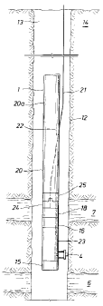
Fig. 2 shows an embodiment of the system of the present invention. As
previously
described in Fig. 1, a conventional sampling tool 1 is deployed into a
borehole 13
that traverses an earth formation 14 to perform logging tests. The tool in
Fig. 2
contains a probe module 4 that is set in contact with the borehole wall 12 and
establishes fluid communication between the formation 14 and the tool 1. A
sample
storage chamber 15 is located below or above the probe. A pump or flow means
and fluid analyzer are also incorporated in the tool as described in Fig. 1,
but are not
specifically identfied in Fig. 2. The pump can be used to remove unwanted
contaminated fluid from the formation through the tool before retrieving
cleaner
uncontaminated fluid. The pumped in formatibn fluid is analyzed for
contamination
content using a fluid analyzer.
It is also possible to flow fluid through the tool without the use of the
pump.
The drill pipe can be ran to a given depth above the test interval with the
circulating
valve open. The valve can then be closed before running to test depth. In this
way
the pressure exerted by the column of fluid enclosed within the drill pipe can
be
preset to a value less than the pressure within the formation. Once the Dual
Packers
are set, and the tool opened it is possible to regulate, or throttle the flow
from the
higher pressure formation, through the tool and into the lower pressure drill
pipe/
tubing by using valves and pressure gauges within the tool. This procedure is
known
as 'Setting the Cushion' and is commonly used to initiate a DST.
Once flow has been initiated, the surface fluid displaced can be measured to
determine the volume of fluid influx from the formation, through the tool into
the drill
CA 02231613 1998-07-16
pipe. This is important, as it provides a surface control over the amount of
reservoir
fluid and contaminants that can enter the drill pipe/ tubing. Under normal
operations,
the influx is regulated by the tool, and flow is stopped by closing a valve
within the
tool. It will always be possible to stop flow by closing the valves at surface
and
downhole in the event of a toot valve failure. The downhole valve will be part
of the
drill pipe/ tubing assembly and is a standard item used in DST.
The analyzer can determine fluid content by measuring certain fluid
properties such as receptivity and optical absorption of speck wavelengths of
light.
Attached to the top portion of the tool is a telemetry module 16 for
transmitting data
from the downhole tool to surface equipment. A power cartridge 18 supplies
power
to the from the surface to the tool. The power cartridge aiso contains a
flowline that
connects the tool flowline to the drill pipe inside volume.
In Fig. 2, a drill pipe or tubing stand 20 is attached to the downhole tool 1.
In
the present invention, the tool is lowered into the borehole by stands of
drill pipe 20a
instead of solely by a wireline 21. The drill pipe stands are connected to
each other
and extend the tool into the borehole similar to the TLCS method. In the
present
invention, the drill pipe stand 20 and 20a serves as a storage chamber for
contaminated formation fluids that are retrieved from the formation during the
sample taking process. One stand of the drill pipe can contain a side-door sub
22:
The side-door sub is a tubular device with a cylindrical shape and has an
opening
on one side. The side opening allows a wireline to enter/exit the string of
drill pipe,
thereby permitting the drill string strands to be added or removed without
having to
disconnect (unlatch and latch) the wireline from surface equipment.
The side-door sub provides a quick and easy means to run the drill pipe/
tubing to test depth without having to unlatch the wireline from the tool.
However,
the side-door sub is not critical to this invention. Furthermore, in certain
situations, it
may be necessary to dispose of the side-door sub for the following reasons:
1/ Complete pressure integrity of the drill pipe is judged necessary.
2/ A quick means to disconnect the drill pipe from the rig is required at the
level of
the sub-sea blow-out preventers (BOP's). This is commonly required in the case
of
floating drilling rigs. This is performed with a special device that is set
within the
11
CA 02231613 1998-07-16
BOP's that connects the drill pipe in the well, beneath the BOP's to the
pressure
tight pipe running from the BOP's to the floating rig itself. The device may
be
disconnected within a period typically of the order of 1-2 minutes, allowing
the
floating rig to be quickly moved from its initial position over the sub-sea
BOP's.
If such a device is required, it will be necessary to run the electrical cable
that
connects to the tool through the inside of the complete length of pipe from
rig to the
tool, dispensing with the side-door sub completely.
A flowline 23 runs throughout the portions of the downhole tool 1 including
the telemetry and power cartridges. These flowlines allow fluids from the
formation
to flow to the various portions of the tool as necessary or to flow through
the tool
and into the drill pipe 20.
This invention contains a means to connect the downhole tool to the wireline
and establish communication with the surface equipment. As shown in Fig. 3, a
downhole electrical assembly 24 is attached to the electrical cartridge 18.
The
downhole electrical assembly can contain the electrical contacts or a male
contact
assembly, a Patching assembly and ports for mud circulation. A pumpdown
electrical
contact 25 is connected to the wirefine 21. The pumpdown electrical assembly
contains the female contact array and is connected to the wireline. The
pumpdown
electrical contact engages the downhofe electrical assembly 24 to establish
communication through the wireline. As will be discussed herein, circulation
ports
are part of a special sub assembly, forming part of the drill pipe/ tubing
assembly to
facilitate forward and reverse circulation of drilling fluids into and out of
the drill pipe
during system operations.
In the operation of the present invention, a downhole testing tool 1 is
attached to the bottom end of the downhole electrical assembly 24 via normal
logging tool connections. Drill pipe 20 is attached to the upper end of the
downhole
electrical assembly. Testing tools are conveyed into the borehole, on the
drill pipe,
down to the desired testing location in the borehole. The pumpdown electrical
assembly 25 is placed in the drill pipe and attached to the wireline 21. The
side-
door sub is then placed on the drill pipe string, if required. The wireline is
extended
through the sub and into the borehole. The system will use drilling mud 30 to
pump
down the electrical assembly through the drill pipe. The use of drilling mud
requires
mud circulation equipment. This circulation equipment is attached to the drill
pipe
12
CA 02231613 1998-07-16
string above the side-door sub portion of the drill string. Once the pump down
electrical assembly 25 is inside the drill pipe, it is simultaneously pumped
(with
drilling fluid) through the drill pipe until the pump down electrical assembly
latches -
and is locked to the downhole electrical assembly.
The mud that is circulated down the drill pipe/ tubing to push the connector
into place is circulated through the circulating ports, referred to above, and
returned
to surface through the drill pipe/ borehole annular space. With the two
electrical
assemblies latched and locked together, the electrical contacts of the of the
two
assemblies are properly aligned. The wireline is now effectively connected to
the
downhole tools. The downhole tools are now powered up to begin operations.
As previously stated, the pump down electrical assembly 25 is lowered into
the drill pipe for contact with the down hole electrical assembly using
drilling fluid.
As shown in Fig. 3, drilling fluid 30 is pumped down the drill pipe 20. The
drilling
fluid forces the pump down electrical assembly 25 down the drill pipe and
returns to
surface through the open circulating ports. Known means inside the drill pipe
keeps
the pump down assembly aligned with the down hole assembly 24 such the
latching
procedure is smooth. As stated above, the drilling fluid is pumped down the
drill
pipe, and exits the drill pipe the port 31. The port is open during
circulation
procedures and is closed during tool operations. The ability to close the port
enables the drill pipe pressure to be adjusted to a desired pressure just
above the
tool. It is important to be able to vary the pressure as necessary when moving
the
tool throughout the borehole. The ability to close the port prevents the port
from
being clogged with debris from the borehole. Debris that clogs the borehole
can
restrict the ability to vary drill pipe pressure as the tool experiences
pressure
changes in the borehole and earth formation.
Referring to FIG. 2, formation fluid flows into the tool through the probe (or
packer module) 4. A pressure difference created in the tool, either by using
the
pump, or by presetting the cushion (referred to above) causes formation fluid
to flow
through the packer module into the tool. As shown in FIG. 2, the formation
contains
the desired uncontaminated fluid 7, but also contains unwanted contaminated
fluid
6. In addition, the contaminated fluid is closer to the borehole and tool than
the
desired fluid. Consequently, the contaminated fluid tends to flow through the
dual
packer and into the tool before the desirable fluid. Therefore, in order to
get a
13
CA 02231613 1998-07-16
desired fluid sample the contaminated fluid must be pumped or flowed from the
formation before a sample can be taken. As stated earlier, large quantities of
this
fluid cannot be stored in conventional sampling tools. Large quantities of the
fluid
can not be dumped in the borehole either. In this invention, the drill pipe
string 20
and 20a serves as chamber in which to store unwanted formation fluids. The
fluids
are taken in through the packer module and analyzed. If the fluid contains
unacceptable amounts of contamination the fluid is pumped through the flowline
23
into the drill pipe string. Because of the length of the drill string, much
larger
quantities of contaminated formation fluid can be sampled and stored without
creating the afore-mentioned problems associated with taking samples using
existing sampling tools. As the fluid is pumped into the tool and analyzed,
the
analyzer will begin to measure properties of the desirable formation fluid. At
this
point, the clean formation fluid is pumped into the stqrage chamber 15. The
tool can
have several sample chambers as is the case in some conventional sampling
tools.
Moreover, if a probe is set some distance from the dual packer module, the
pressure
observed at the probe may vary as fluid is withdrawn from the formation into
the
tool. The nature of the pressure changes both at the packer module and the
observation probe provide independent estimates of formation permeability,
damage
and formation permeability anisotropy.
After the sampling procedure is completed, the unwanted fluid stored in the
drill pipe chamber can be disposed of before the-sampling tool can be brought
to the
surface if necessary. The disposing of the unwanted contaminated may be
necessary for safety reasons. The composition of the contaminated fluid could
be
unknown and could contain chemicals that are harmful if not property handled.
Well
sites usually have equipment available that is designed to handle hazardous
materials.
The present invention provides a way of disposing of the contaminated fluid
by pumping a different fluid down the borehole annulus, through the port 31
and into
the drill pipe. The contaminated fluid above the port is forced upward by the
fluid
entering through the port. As more fluid enters through port 31, the
contaminated
fluid is forced upward to the surface. Surface equipment is available that is
designed to handle the hazardous materials. Fluid continues to be pumped into
the
drill pipe until the amount of contaminated fluid remaining in the drill pipe
is below
the hazardous levels. Another method of retrieving is to create a pressure
drop in
14
CA 02231613 1998-07-16
the chamber above the stored fluid. This pressure drop would cause the fluid
to
flow upward to the surface and be captured by the surface equipment designed
to
handled such fluid.
Fig. 4 shows the details of an embodiment of the present invention. Drill pipe
20 is connected to the sampling tool 1. Drilling fluid (usually drilling mud)
30 is
pumped down the drill pipe 20 to lower a female electrical assembly 25
attached to
a cable 21 down the drill pipe until the assembly 25 engages and latches with
a
down hole male electrical assembly 34 establishing contact via electrical
contacts
35. Electrical wiring 36 electrically connects the downhole electrical
assembly to the
sampling tool. During this procedure, as the drilling fluid flows down the
drill pipe
the fluid pressure forces a circulation piston 40 down thereby opening a
circulation
port 31. Drilling fluid 30 exits the drill pipe through,the opened circulation
port 31.
The circulation piston 40 is attached via a spring 46 to the hydraulic motor
47. As
the female assembly engages the male assembly the lead portion of the female
assembly (which is greater in diameter than the remaining portion of the
assembly)
travels pass the latch fingers 37, the fingers latch to the smaller portion of
the
assembly securing the two assemblies together. Centralizers 38, which are
spaced
120° apart mechanically keep the female assembly 25 centralized in the
docking
head assembly 39 and properly aligned during the latching process to assure
ease
of latching the female and male assemblies. The latching procedure establishes
electrical communication between the sampling tool and the surface equipment
via
wires 36. After the electrical contacts have latched, pumping fluid down the
drill pipe
ceases. At this point, springs 46 force the circulation piston 40 up to the
initial
position, thereby closing the circulation ports 31. With the electrical
communication
established and the circulation ports closed, the system is ready to begin
formation
fluid sampling operations.
In this description, packers 44 seal off a portion of the formation and the
tool '
begins the sampling process. Hydrostatic pressure in the drill pipe can be
lowered
to provide an initial "draw down pressure" (pressure drop). A flowline 23 from
the
tool 1 to the drill pipe 20 is opened via flowline shut-of valve 43. The
flowline shut-
off valve in the downhole electrical assembly opens the flowline to allow
fluid
communication from the drill pipe to the sampling tool 1. The formation sample
will
begin to flow through the flowline from the formation through the toolstring
and
downhole electrical assembly and exits the flowline at the exit port 33 and
into the
CA 02231613 1998-07-16
drill pipe 20. When contamination levels in the formation fluid are reduced to
an
acceptable and desirable level, formation fluid is diverted into a sample
chamber.
At the completion of the sampling operation, the flowline shut-off valve 43 is
closed to isolate the toolstring flowline from the downhole electrical
assembly
flowline 23. The sampling tool probe or packers are retracted. The
contaminated
fluid stored in the drill pipe now has to be moved to the surface. in order to
bring the
fluid to the surface, the hydrostatic pressure differential between the drill
pipe and
annuals 13 are equalized. The downhole electrical assembly hydraulic cylinder
42
is activated and the circulation piston 40 is pull down uncovering the
circulation ports
31. In order to bring the contaminated fluid to the surface, fluid is pumped
down the
borehole alongside the drill pipe. The opened circulation port allows the
fluid to
enter the drill pipe below the contaminated fluid. ,
The contaminated formation fluid is recovered from the drill pipe by reverse
circulating mud or fluid. Reverse circulation is accomplished by pumping mud
down
the annuals through the mud circulation ports 31 in the docking head 39 and up
through the drill pipe 20.
The system that controls the movement of the circulation piston 40 has
hydraulic cylinder 42 that contains a hydraulic piston which is moved back and
forth
by pumping hydraulic oil either above or below it. The hydraulic piston is
connected
to the circulation piston 40 which opens and closes the circulation port .when
the
electric motor and hydraulic pump 47 are activated. This operation is needed
for the
reverse circulation function. A hydraulic system compensator 48 allows the
hydraulic oil needed for the hydraulic pump and electric motor to be
pressurized to
the same pressure as the mud pressure inside the drill pipe. This compensator
consists of the compensator piston and a pop-off valve and spring. This
compensator provides electrical and mechanical reliability. A Silicon oil
system
compensator 49 allows Silicon oil needed for the male contacts and associated
wiring to be pressurized to same pressure as the mud (fluid) pressure in the
drill
pipe. This system also consists of a compensation piston, pop-off valve and
spring.
This system provides electrical reliability. A mud compensation port 50 allows
mud
pressure from inside the drill pipe to be applied to the hydraulic system
compensating piston and the silicon compensating system. This allows both
systems to be pressure compensated.
16
CA 02231613 1998-07-16
The present invention also enables a testing and sampling tool to be used in
a horizontal borehofe. As shown in Fig. 5, stands of drill pipe 20 and 20a
are'
attached to each other and extended into the borehole. The borehole bend 35 is
of
an angle that is wide enough to allow the connected drill pipe to extend
through the
bend. The tool 1 is attached to the drill pipe as in vertical borehole
operations. The
support of the tool by the drill pipe enables the tool to take measurements of
the
formation by the probe 4 in the shown position. This particular measurement
would
not be possible using only a conventional wireline 21 and associated
equipment.
The method and apparatus of this invention provides significant advantages
over the cun-ent art. The invention has been described in connection with its
preferred embodiment. However, it is not limited thereto. For instance a multi-
sample storage chamber can be implemented with this invention. The tool string
could use IRIS, a tubing tester valve, annular sample jars. If necessary, the
tool
could be hung off with EZ Tree. The actual configuration would like other
tools
would depend needs of a specific job. Changes, variations and modifications to
the
basic design may be made without departing from the inventive concepts in this
invention. In addition, these changes, variations and modifications would be
obvious to those skilled in the art having the benefit of the foregoing
teachings. All
such changes, variations and modifications are intended to be within the scope
of
the invention which is limited only by the following claims.
17