Language selection

Search

Patent 2231678 Summary

Third-party information liability

Some of the information on this Web page has been provided by external sources. The Government of Canada is not responsible for the accuracy, reliability or currency of the information supplied by external sources. Users wishing to rely upon this information should consult directly with the source of the information. Content provided by external sources is not subject to official languages, privacy and accessibility requirements.

Claims and Abstract availability

Any discrepancies in the text and image of the Claims and Abstract are due to differing posting times. Text of the Claims and Abstract are posted:

  • At the time the application is open to public inspection;
  • At the time of issue of the patent (grant).
(12) Patent: (11) CA 2231678
(54) English Title: INJECTION MOLDING MACHINE
(54) French Title: MACHINE A MOULER PAR INJECTION
Status: Deemed expired
Bibliographic Data
(51) International Patent Classification (IPC):
  • B29C 45/17 (2006.01)
(72) Inventors :
  • URBANEK, OTTO (Austria)
  • WIMBAUER, GERHARD (Austria)
(73) Owners :
  • ENGEL MASCHINENBAU GESELLSCHAFT MBH (Austria)
(71) Applicants :
  • ENGEL MASCHINENBAU GESELLSCHAFT MBH (Austria)
(74) Agent: FETHERSTONHAUGH & CO.
(74) Associate agent:
(45) Issued: 2004-02-24
(86) PCT Filing Date: 1997-07-10
(87) Open to Public Inspection: 1998-01-22
Examination requested: 1999-07-07
Availability of licence: N/A
(25) Language of filing: English

Patent Cooperation Treaty (PCT): Yes
(86) PCT Filing Number: PCT/AT1997/000160
(87) International Publication Number: WO1998/002291
(85) National Entry: 1998-03-11

(30) Application Priority Data:
Application No. Country/Territory Date
96111233.1 European Patent Office (EPO) 1996-07-12
GM 541/96 Austria 1996-09-16

Abstracts

English Abstract


The invention relates to an injection moulding machine with a substantially C-
shaped machine frame with one leg on which a stationary
die platen is mounted and with another leg on which a closing mechanism for
driving a movable die platen is mounted. An articulated part
which comprises a girder extending in the longitudinal direction of the
machine is arranged between at least one die platen and the machine
frame and is deformed when a closing force is applied which tips the die
platen in relation to the associated leg of the machine frame. The
horizontal central axis (8) of the die platen, which axis (8) is determined by
centring means for the die extends completely inside the girder
(6) and the cross-section of the articulated part (7) increases in size in the
same direction, starting from the central girder (6).


French Abstract

Machine à mouler par injection comprenant un châssis en forme générale de "C", sur l'une des traverses duquel il est prévu, pour le moule, un plateau de fixation stationnaire et, sur l'autre traverse, un mécanisme de fermeture pour l'entraînement d'un plateau de fixation mobile. Entre au moins un plateau et le châssis est disposée une pièce articulée comprenant des branches s'étendant dans le sens longitudinal de la machine, cette pièce étant déformée lorsqu'une force de fermeture est appliquée, permettant ainsi au plateau de fixation de basculer par rapport à la traverse correspondante du châssis. L'axe horizontal (8) des plateaux de fixation, déterminé par les dispositifs de centrage du moule s'étend, dans sa totalité, à l'intérieur de la branche (6), et la section de la pièce articulée (7) s'agrandit dans le même sens, à partir de la branche centrale (6).

Claims

Note: Claims are shown in the official language in which they were submitted.


5

CLAIMS:

1. An injection molding machine comprising a
substantially C-shaped machine frame, on one limb of which
is mounted a stationary mold mounting plate and on the other
limb of which is mounted a closing mechanism for driving a
movable mold mounting plate, wherein the free ends of the
limbs of the machine frame, which are not connected by frame
beams, deform under the influence of the closing force which
occurs during the closing operation, and wherein arranged
between at least one mold mounting plate and the machine
frame is a hinge portion which includes a bar portion
extending in the longitudinal direction of the machine,
which hinge portion is deformed when the closing force is
applied whereby the mold mounting plate is tilted relative
to the associated limb of the machine frame, characterised
in that the cross-section of the hinge portion increases
continuously starting from the bar portion.

2. An injection molding machine as set forth in
claim 1, wherein the hinge portion includes at least one
flange connected to the bar portion, the machine including
an abutment portion extending toward the movable mold
mounting plate and connected to the flange for engaging the
movable mold mounting plate when the movable mold mounting
plate tilts toward the abutment portion.

3. An injection molding machine as set forth in
claim 2 characterised in that the abutment portion bears
against the movable mold mounting plate by way of a spring.

4. An injection molding machine as set forth in
claim 2 characterised in that the abutment portion co-
operates with a counter-portion which is anchored in the
movable mold mounting plate and which engages behind the
abutment portion.


Description

Note: Descriptions are shown in the official language in which they were submitted.


CA 02231678 1998-03-11
FILE, F~h~N-TH~S A .. ~°_ yy-yr
Tf~TRANSLATBwN
W098/02291 PCT/AT97/00160
Injection molding machine
The invention relates to an injection molding machine comprising a
substantially C-shaped machine frame, on one limb of which is mounted a
stationary mold mounting plate and on the other limb of which is mounted
a closing mechanism for driving a movable mold mounting plate, wherein
the free ends of the limbs of the machine frame, which are not connected
by frame beams, deform under the influence of the closing force which
occurs during the closing operation, and wherein arranged between at
least one mold mounting plate and the machine frame is a hinge portion
which includes a bar portion extending in the longitudinal direction of
the machine, which hinge portion is deformed when the closing force is
applied whereby the mold mounting plate is tilted relative to the
associated limb of the machine frame.
Insofar as injection molding machines without frame beams have
been proposed in earlier decades, the attempt has generally been to
minimise the deformation of the C-shaped machine frame, which occurs
under the influence of the closing force. Machines without frame beams
only became of noteworthy practical significance however since designs
have chanced over to permitting a certain degree of deformation of the
machine frame and compensating for that deformation by suitable
measures. .n that respect it is possible to permit deformation as
between eacn of the two mold mounting plates and the associated limb of
the machine frame, ~,vhich deformation provides precise compensation for
the spreading effect in respect of the limbs of the machine frame, so
that the mold separation plane does not experience a change in its
vertical position when the closing pressure is applied. In that respect
the arrangement may be such (see EP 0 722 820 A1) that the upper end of
the limb ;:~ the machine frame pivots in opposite relationship to the
limb ~tselY. In contrast. improved localisation of the pivot axes is
achieved . separate deformable holding portions are fitted between the
moil mountWa plates and the machine frame, as is shown in DE 295 16 398
U1.

CA 02231678 2003-08-05
23739-322
2
In the case of the beam-less injection molding
machine in accordance with EP 0 311 133 B, which in the
meantime has become the classic design configuration, it is
possible to manage with one pivot axis insofar as the
stationary mold mounting plate is rigidly connected to the
machine frame and the movable mold mounting plate is mounted
tiltably so that it can also perform the pivotal movement
that the fixed mold mounting plate experiences under the
influence of the closing force. Figures 3 through 6 of
AT 400 022 B show a corresponding structural configuration
corresponding to the definition set forth in the opening
part of this specification.
The known construction disclosed in AT 400 022 B
lays the emphasis entirely on the pivotal movement of the
movable mold mounting plate under the influence of the
closing force. Openings extending over a large part of the
cross-section permit compression of the lower part of the
bar portion, in that sense. In comparison the invention is
based on the consideration that, with the closing pressures
necessary for injection molding, it is not the flexing of
the bar portion but the aspect of carrying the closing force
that represents the actual problem. What is involved is
carrying the closing force without the material of the hinge
portion suffering plastic deformation while the hinge
portion is sufficiently bent by the moment that occurs
between the two mold halves to compensate for the movement
involving opening of the limbs of the machine frame. That
is achieved by virtue of a configuration in which the cross-
section of the hinge portion increases continuously starting
from the central bar portion. By virtue of that measure,
the pivot axis of the movable mold mounting plate is
localised in the central region of the hinge portion. In

CA 02231678 2003-08-05
23739-322
2a
addition the arrangement guarantees the connection to the
adjacent parts of the machine which, by virtue of the wider
contact surface, can be of lower quality than the hinge
portion itself.
In accordance with a broad aspect of the present
invention, there is provided an injection molding machine
comprising a substantially C-shaped machine frame, on one
limb of which is mounted a stationary mold mounting plate
and on the other limb of which is mounted a closing
mechanism for driving a movable mold mounting plate, wherein
the free ends of the limbs of the machine frame, which are
not connected by frame beams, deform under the influence of
the closing force which occurs during the closing operation,
and wherein arranged between at least one mold mounting
plate and the machine frame is a hinge portion which
includes a bar portion extending in the longitudinal
direction of the machine, which hinge portion is deformed
when the closing force is applied whereby the mold mounting
plate is tilted relative to the associated limb of the
machine frame, characterised in that the cross-section of
the hinge portion increases continuously starting from the
bar portion.
The flange-like configuration of the ends of the
hinge portion according to the invention makes it possible
to form an abutment on one of the flanges in one piece
therewith, which abutment limits the pivotal movement of the
movable mold mounting plate in one and preferably both
directions.

CA 02231678 2003-08-05
23739-322
Details of the invention are described hereinafter with reference
to the drawing in which:
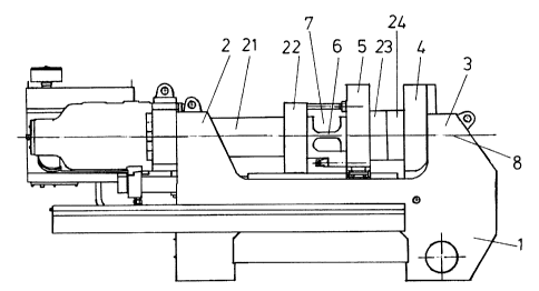
Figure 1 is a diagrammatic side view of an injection molding
machine according to the invention, Figure 2 is a view on an enlarged
scale of a detail from Figure l, and Figure 3 is a view on an enlarged
scale of a detail from Figure 2.
The injection molding machine shown in Figure 1 has a machine
frame 1 whose particularity is that the upwardly projecting limbs 2 and
3 of the machine frame 1 are not connected by frame beams. Injection of
plastic material into the mold which is to be arranged between the
stationary mold mounting plate 4 and the movable mold mounting plate 5
is effected by means of an injection unit (not shown) while the mold
mounting plates 4, 5 are pressed together by a for example hydraulic
closing arrangement. In that situation, the C-shaped machine frame is
slightly opened up. In the illustrated embodiment, it is assumed that
the mold mounting plate 4 also performs the movement of the limb 3 and
a single hinge portion 7 permits a pivotal movement of the mold
mounting plate 5 so that the mold mounting plates 4 and 5 remain
parallel even under the influence of the closing pressure. The hinge
portion 7 which is shown in detail in Figure 2 comprises a
longitudinally directed bar portion 6 whose cross-section forms a
horizontal rectangle. The bar portion 6 enlarges continuously in both
directions
to constitute flanges 9 and 10 which are connected to
the adjoining plates 5 and 22. The center line 8 wf~ich is defined by
the centering devices for the mold halves 23,24 said centering
devices being provided on the mold mounting plates 4, 5, extend
entirely in the interior of the bar portion 6 and preferably in
slightly displaced relationship into the lower half thereof.
When closing pressure is applied to the closed mold by means of
the closing arrangement 21, that pressure is passed through the bar
portion 6 which curves upwardly as soon as the mold mounting plates 4
and 5 incline jointly in the clockwise direction. That inclination is
limited by an abutment portion 11 which is in one piece with the flange
10 and which bears (see Figure 3) by way of a plate spring 12 against
the mold mounting plate 5. The pivotal movement of the mold mounting
3

CA 02231678 1998-03-11
plate 5 relative to the rail 19 on which the mold mounting plate 5 is
movable by means of a slide shoe is made possible in that case by a
resilient connection between the slide shoe 18 and the mold mounting
plate 5. In the event of an overload the pivotal movement of the mold
mounting plate 5 in the clockwise direction is terminated when the gap
16 is completely closed.
A movement of the mold mounting plate 5 in the counter-clockwise
direction, as is possible in particular when the mold is arranged too
high, is limited by a counter-portion or check portion 20 which engages
behind the abutment portion 11 and which comes to bear against the
abutment portion 11 when the gap 17 is closed. That situation occurs in
the unloaded condition. The counter-portion 20 comprises a
screwthreaded pin 13 which is fixed in the mold mounting plate 5 and
which carries an abutment nut 14 fixed by a screw securing means 15.
a

Representative Drawing
A single figure which represents the drawing illustrating the invention.
Administrative Status

For a clearer understanding of the status of the application/patent presented on this page, the site Disclaimer , as well as the definitions for Patent , Administrative Status , Maintenance Fee  and Payment History  should be consulted.

Administrative Status

Title Date
Forecasted Issue Date 2004-02-24
(86) PCT Filing Date 1997-07-10
(87) PCT Publication Date 1998-01-22
(85) National Entry 1998-03-11
Examination Requested 1999-07-07
(45) Issued 2004-02-24
Deemed Expired 2010-07-12

Abandonment History

There is no abandonment history.

Payment History

Fee Type Anniversary Year Due Date Amount Paid Paid Date
Registration of a document - section 124 $100.00 1998-03-11
Application Fee $300.00 1998-03-11
Maintenance Fee - Application - New Act 2 1999-07-12 $100.00 1999-07-06
Request for Examination $400.00 1999-07-07
Maintenance Fee - Application - New Act 3 2000-07-10 $100.00 2000-07-05
Maintenance Fee - Application - New Act 4 2001-07-10 $100.00 2001-06-28
Maintenance Fee - Application - New Act 5 2002-07-10 $150.00 2002-06-25
Maintenance Fee - Application - New Act 6 2003-07-10 $150.00 2003-07-04
Final Fee $300.00 2003-12-16
Maintenance Fee - Patent - New Act 7 2004-07-12 $200.00 2004-07-05
Maintenance Fee - Patent - New Act 8 2005-07-11 $200.00 2005-06-29
Maintenance Fee - Patent - New Act 9 2006-07-10 $200.00 2006-06-27
Maintenance Fee - Patent - New Act 10 2007-07-10 $250.00 2007-06-21
Maintenance Fee - Patent - New Act 11 2008-07-10 $250.00 2008-06-30
Owners on Record

Note: Records showing the ownership history in alphabetical order.

Current Owners on Record
ENGEL MASCHINENBAU GESELLSCHAFT MBH
Past Owners on Record
URBANEK, OTTO
WIMBAUER, GERHARD
Past Owners that do not appear in the "Owners on Record" listing will appear in other documentation within the application.
Documents

To view selected files, please enter reCAPTCHA code :


To view images, click a link in the Document Description column. To download the documents, select one or more checkboxes in the first column and then click the "Download Selected in PDF format (Zip Archive)" or the "Download Selected as Single PDF" button.

List of published and non-published patent-specific documents on the CPD .

If you have any difficulty accessing content, you can call the Client Service Centre at 1-866-997-1936 or send them an e-mail at CIPO Client Service Centre.


Document
Description 
Date
(yyyy-mm-dd) 
Number of pages   Size of Image (KB) 
Representative Drawing 1998-06-16 1 7
Description 2003-08-05 5 205
Drawings 2003-08-05 3 58
Claims 2003-08-05 1 45
Cover Page 1998-06-16 1 52
Representative Drawing 2004-01-22 1 10
Cover Page 2004-01-22 1 44
Abstract 1998-03-11 1 17
Claims 1998-03-11 1 35
Description 1998-03-11 4 160
Drawings 1998-03-11 3 57
PCT 1998-03-11 10 322
Assignment 1998-03-11 3 122
Prosecution-Amendment 1999-07-07 1 41
Prosecution-Amendment 2003-04-14 2 33
Fees 2003-07-04 1 36
Correspondence 2003-12-16 1 32
Prosecution-Amendment 2003-08-05 8 277
Fees 1999-07-06 1 37
Fees 2000-07-05 1 38
Fees 2007-06-21 1 35