Note: Descriptions are shown in the official language in which they were submitted.
CA 02231816 1998-OS-15
TITLE OF THE INVENTION
METHOD AND APPARATUS FOR HALFTONE RENDERING
OF A GRAY SCALE IMAGE USING A BLUE NOISE MASK
This application is a divisional of Canadian patent application Serial No.
2,097,508 filed internationally on December 3, 1991 and entered Nationally on
June l,
1993.
BACKGROUND OF THE INVENTION
The present invention relates generally to the halftoning of images. More
particularly, the present invention relates to a method of and system for
rendering a halftone
by utilizing a pixel-by-pixel comparison of the gray scale image against a
blue noise mask.
Many printing devices are not capable of reproducing gray scale images
because they are bi-level. As a result, the binary representation of a gray
scale image is a
necessity in a wide range of applications such as laser printers, facsimile
machines,
lithography (newspaper printing), liquid crystal displays and plasma panels.
Gray scale
images are typically converted to binary images using halftone techniques.
Halftoning
renders the illusion of various shades of gray by using only two levels, black
and white, and
can be implemented either digitally (facsimile machines, laser printers) or
optically
(newspaper printing).
CA 02231816 1998-OS-15
-2-
Halftoning algorithms are classified into point and neighborhood algorithms
according to the number of points from the input gray scale image required to
calculate one
output point in the output binary image. In the case of digital halftoning,
points correspond
to pixels. In point algorithms, the halftoning is accomplished by a simple
pointwise
comparison of the gray scale image against a nonimage, usually aperiodic (but
not always)
array or mask. For every point in the input image, depending on which point
value (the gray
scale image or the mask) is larger, either a 1 or 0 is placed respectively at
the corresponding
location in the binary output image. Halftoning using neighborhood algorithms
is not done
by simple pointwise comparison, but usually requires filtering operations that
involve a
number of points from the input gray scale image in order to calculate one
point in the
output image.
At present, given the existing halftoning algorithms, the choice for a
specific
halftoning algorithm depends on the target device and always requires a trade-
off between
image quality and speed. Neighborhood halftoning algorithms result in a good
image
quality (although the image is not completely artifact free), but they are
slow and cannot be
optically implemented. That leaves point algorithms as the only choice for
optical
applications such as newspaper printing. Point algorithms are fast and are
suitable for all
target devices, but the output usually suffers from artifacts such as periodic
artifacts and
false contours.
The halftoning system disclosed herein utilizes a point algorithm, and
combines the output image quality of neighborhood algorithms with the speed
and wide
application range of point algorithms. A point algorithm is utilized and the
halftoning is
CA 02231816 1998-OS-15
-3-
achieved by a pixelwise comparison against a nonimage array, called the "blue
noise" mask.
The digital halftoning of images with multiple levels, such as gray scale
levels,
is known in the art. Two major techniques are currently in use. They are the
ordered dither
and the error diffusion methods. See Digital Halftonin~ by R. Ulichney, MIT
Press,
Cambridge, Massachusetts (1987). See also R. W. Floyd and L. Steinberg,
"Adaptive
algorithm for spatial gray scale", SID International Symposium Digest of
Technical Papers,
pps. 36-37. The Floyd and Steinberg paper is directed to the digital
halftoning of a gray
scale.
The major ordered dither techniques are the clustered-dot dither and dispersed-
dot dither techniques. A white noise random dither technique is seldom
utilized because it
produces the poorest quality image and, of the other two dither techniques,
clustered-dot is
by far the most used. Both of those techniques are based upon a threshold
screen pattern
that is of a fixed size. For example, 6 x 6 threshold screens may be compared
with the
digital input values. If the input digital value is greater than the screen
pattern number, a 1
is produced and, if it is less, a 0 value is assigned. The number of levels
that can be
represented using either technique depends on the size of the screen. For
example, a 6 x 6
screen can produce 36 unique levels.
More levels can be achieved with larger patterns, however, a reduction in the
effective resolution occurs because the ability to transition among levels is
at a coarser
pitch. At the pixel rate of about 300 to 500 per inch, which is the average
pixel rate of
copiers and laser printers, the pattern artifacts are visible for screen
patterns larger than
4 x 4, and, since 16 levels do not provide an adequate precision for typical
continuous-tone
CA 02231816 1998-OS-15
-4-
imagery, a suboptimal resolution is usually obtained.
One solution to such a problem is disclosed by Ulichney in a paper "Dithering
with Blue Noise" published in the Proceedings of the IEEE, Vol. 76, No. 1,
January 1988.
In that article, a method of spatial dithering is described which renders the
illusion of the
continuous-tone pictures on displays that are capable of only producing binary
picture
elements. The method produces a blue noise pattern high frequency white noise
from a
filter to provide desirable properties for halftoning. More specifically,
Ulichney uses
perturbed-weight error diffusion methods which when digitally implemented run
at a much
slower speed (approximately 100 times slower) than is attainable with the
present invention.
Error diffusion techniques, such as that disclosed in the Ulichney IEEE
article,
are fundamentally different from ordered dither techniques in that there is no
fixed screen
pattern. Rather, a recursive algorithm is used that attempts to correct errors
made by
representing the continuous signal by binary values.
The error diffusion method described by Ulichney, and others, such as Floyd
and Steinberg, also has the disadvantage that it requires scanning,
convolution-style
calculations and, although it can be implemented for use with copiers,
facsimile machines,
etc., requires local calculations. It cannot, however, be optically
implemented. In addition,
all error diffusion techniques, including those described by Ulichney and
Floyd and
Steinberg, show scanning and start-up artifact , which are not present in the
instant
invention. Also, while Ulichney describes a method that produces blue noise,
the blue noise
patterns produced by the present invention are more isotropic than those
produced by
Ulichney or other error diffusion methods. Utilizing ordered dither methods
produces
CA 02231816 1998-OS-15
-S-
notably periodic patterns that are even much more obtrusive than those
produced by error
diffusion methods.
In some prior art systems, all dot profiles corresponding to different gray
levels were derived independently, as if each grade level was its own special
case. Thus, for
example, in United States Patent No. 4,920,501, to Sullivan et al., many
individual dot
profiles, corresponding to the desired number of gray levels, must be stored.
In the present
invention, on the other hand, dot profiles are built "on top of the profiles
from lower gray
levels, such that a single valued 2-dimensional function, that is, the
cumulative array or blue
noise mask, can be constructed. When that single valued function is
thresholded at any
level, the resulting binary pattern is exactly the blue noise dot profile
design for that
particular gray level, p(i~j,g), where p can be one or zero corresponding to
black or white, i
and j are coordinates of pixels, and g represents a gray level 0<g<1.
Another drawback to prior art methods is that the dot profile for a given gray
level was designed to have blue noise properties by indirect methods, such as
using an error
diffusion filter with perturbed weights (Ulichney) or by a "simulated
annealing" algorithm,
as in United States Patent No. 4,920,501. The method disclosed herein is
advantageous
with respect to the prior art in that the desired blue noise power spectrum is
produced
through the use of a filter on the dot profile and is implemented directly in
the transform
domain. Such filtering results in a nearly ideal blue noise pattern with
implicit long-scale
periodicity because of the circular convolution implicit in the use of
discrete Fourier
transforms. However, the filtered pattern is no longer binary. Thus, a
minimization of error
approach is utilized in which the largest differences between the ideal,
filtered, blue noise
CA 02231816 1998-OS-15
_(j_
pattern and the unfiltered dot profile are identified. The magnitude and
location of those
differences indicate the pixels in which ones and zeros could be changed to
produce a more
ideal blue noise dot profile.
Display devices, including printing devices as well as media, have their own
S unique input-output characteristics. In some uses, such as medical
ultrasound imaging, the
user has traditionally been provided with some control as to the final gray
scale mapping.
For example, the user may be able to select between high and low contrast
images. The
display and film characteristics, however, must be accounted for in each
rendition.
In the area of halftone rendering, traditional halftone screens using small
(for
example, 8 x 8 pixel) kernels provide only limited degrees of freedom to alter
the input-
output characteristics and usually a linear cumulative distribution function
(CDF) has been
reported. See Digital Halftonin~ by R. Ulichney, MIT Press, Cambridge,
Massachusetts
( 1987). See also, R. Bayer, "An Optimum Method for 2 Level Rendition of
Continuous
Tone Pictures", IEEE International Conf. Comm., 1973, and G. C. Reid,
Postscript
Loge Program Design (green book), Addison-Wesley Publishing Co., New York, New
York (1988), page 137. By a linear CDF, it is meant that 10% of the halftone
kernel pixel
contents will be less than 10% of the maximum value and that 50% of the pixels
will
contain values less than 50% of the maximum values, and so forth.
In the case of the blue noise mask method disclosed herein, a large
unstructured pattern of, for example, 256 x 256 pixel kernels, provides
sufficient degrees of
freedom to modify the cumulative distribution function so as to provide both
linear and non-
linear mappings of input and output characteristics. That makes it possible to
construct
CA 02231816 1998-OS-15
7_
specialized blue noise masks in which a particular printer output and media
characteristics
can be compensated for by a modified blue noise mask generated as disclosed in
this
application.
The present inventive method herein may also be applied to color halftoning,
by independently thresholding each of the component colors against the
disclosed blue noise
mask and then overprinting. Such method produces a pleasing pattern without
any blurring
of the image. Such method is a great improvement over the known prior art,
which is
discussed below.
In United States Patent No. 5,010,398, there is disclosed a method for color
corrections by dry dye etching using a photographically produced mask which
may be used
in the production of printing plates for printing reproductions of colored
originals and in
which a contact print is overexposed to a photographic mask. The photographic
mask is
constituted so as to isolate a selected area in addition to being exposed
normally for
obtaining an exact copy of an original halftone separation. The mask is
electronically
generated by scanning each separation, digitizing each signal and then storing
the digital
values in a digital storage device.
United States Patent No. 4,974,067 relates to a mufti-step digital color image
reproducing method and apparatus which separates an original image into a
plurality of
color components to produce image data associated with each respective one of
the color
components. The image data are individually processed to provide record color
component
density data which data are used to record a halftone representation pattern
of that color
component.
CA 02231816 1998-OS-15
An apparatus and methods for digital halftoning is disclosed in United States
Patent No. 4,924,301 for producing halftone screens or color separations from
continuous
tone intensity signals that are supplied by an optical scanner. Using a
digital signal
processor, the continuous tone intensity values are processed to establish
memory maps
which, in conjunction with a digital data output device such as a laser
printer, produces the
desired halftone screen. The digital signal processor utilizes a dither matrix
in order to
produce halftone screens having a screen angle that does not substantially
differ from the
screen angles of the yellow, cyan and magenta color separations in
conventional four color
halftone printing. A dither array is also utilized to produce the halftone
screens having a
screen angle that substantially differs from the screen angle used in the
black halftone color
separation in conventional four color halftone printing.
United States Patent No. 4,342,046 relates to a contact screen for making
color
separation halftone blocks for use in a picture reproducing machine in which a
plurality of
halftone screens having different screen angles are arranged on a base film in
the
corresponding positions of color separation reproduction pictures to be
reproduced on the
base film and transparent blank spaces are formed between two adjacent
halftone screens.
A method and apparatus for making monochrome facsimiles of color images
on color displays is disclosed in United States Patent No. 4,308,533 for
making 35MM
color slides from a color image created on a color cathode tube terminal.
United States
Patent No. 3,085,878 relates to the preparation of traditional halftone
screens for color
separation.
United States Patent No. 4,657,831 relates to the production of
CA 02231816 1998-OS-15
_c
electrophotographic color proofs of halftone dot pattern images which closely
simulate the
dot gain of prints made with lithographic plates and liquid inks.
A process for the production of photographic masks is disclosed in United
States Patent No. 4,997,733 in which such masks are used for the tonal
correction by dry dot
etching in which the selection of a particular halftone color separation image
or overlaying
registering combination of halftone color separation images is determined on
the basis of
optical density differences in at least one such halftone color separation.
Such differences
include differences in contrast, between each area to be isolated as a
substantially
transparent area, and at least one particular background area surrounding each
area to be
isolated.
United States Patent No. 4,477,833 is directed to a method of color conversion
with improved interpolation in which an apparatus for converting a color image
from one
colored space to another colored space includes a memory which stores a finite
number of
output signals which represent colors in the output space and which is
addressed by signals
representing a color in the input space. The interpolation process is utilized
in order to
derive an output color value for an input color located between colors stored
in the memory.
A method and apparatus for producing halftone printing forms with rotated
screens based upon randomly selected screen threshold values is disclosed in
United States
Patent No. 4,700,235. The screens have arbitrary screen angles and screen
width. Screen
dots are exposed on a recording media by means of a recording element whose
exposure
beam is switched on and off by a control signal.
None of the foregoing references have the advantages of the use of the blue
CA 02231816 2001-08-30
noise mask method disclosed herein in producing pleasing, isotropic, non-
dumpy,
moue resistant patterns with only some spreading out of the color or ink but
with no
blurring of the image.
SUMMARY AND OBJECTS OF THE INVENTION
In view of the foregoing, it should be apparent that there still exists a need
in
the art for a machine for the halftone rendering of gray scale images in which
a digital
data processor is utilized in a simple and precise manner to accomplish the
halftone
1 o rendering to provide a binary scale image which is characterized by the
pixelwise
comparison of the image being analyzed against a blue noise mask. There also
exists a
need for the modification of such halftone rendering machine in order to
counter some
undesirable printer and media dependent effects such that the halftone
rendering of
gray scales is modified to produce input and output characteristics unique to
a
particular type of device or media and in which the images produced are
superior to
those produced without such modification.
It should likewise be apparent that there still exists a need in the art for a
machine for color halftoning by independently thresholding each of the
component
colors against a blue noise mask in order to produce a pleasing, isotropic,
non-
dumpy, moue resistant pattern with only some spreading out of the color or ink
but
with no blurring of the image.
More particularly, it is an object of this invention to provide a machine for
the
halftone rendering of a gray scale image which has a simple and reliable
mechanism
for producing the desired image.
CA 02231816 2001-08-30
1~
Still more particularly, it is an object of this invention to provide a
machine for
the halftone rendering of a gray scale image which can be implemented either
digitally or optically.
It is another object of this invention to provide a machine for the halftone
rendering of a gray scale image which tailors the image thus produced to
compensate
for particular output printer and media characteristics such that the
undesired display
of media characteristics can be substantially eliminated.
It is yet another object of this invention to provide a machine for the
halftone
rendering of continuous tone color images such that pleasing images are
produced
to with little spreading out of the color and with no blurring of the image.
Briefly described, these and other objects of the invention are accomplished
by
generating a blue noise mask which, when thresholded at any gray level g,
produces a
blue noise binary pattern appropriate for that gray level. After the blue
noise mask has
been generated, it is stored in a PROM. The image to be halftoned is then read
by a
scanner on a pixel-by-pixel basis and compared to the corresponding stored
pixel in
the blue noise mask to produce the resulting binary array. The binary image
array is
then converted to a binary display which is the resultant halftoned image.
After the blue noise mask has been generated and stored, it may be modified
to tailor it for a particular output printer and media characteristics such
that
2o compensation is provided in a blue noise mask for undesired display and
media
characteristics. The blue noise mask is modified by altering the first order
statistics or
the cumulative distribution function (CDF) to counter such undesirable printer
and
media dependent effects. The blue noise mask may be modified in a variety of
ways,
all of which usually include punching the blue noise mask. Punching the blue
noise
mask involves setting the extreme low values to a certain minimum value, for
CA 02231816 2001-08-30
12
example, 0 and setting the extreme high values to a certain maximum value, for
example 255. The values between the maximum and the minimum are then re-
linearized.
The method of generating and utilizing the blue noise mask discussed above
can also be applied to color halftoning, by independently thresholding each
one of the
component colors against the blue noise mask and then overprinting the
halftoned
component color images. The blue noise mask can also be shifted by one pixel
before
it is used on each of the different color planes. In that manner, the color
energy is
spread out over a larger space. For example, the blue noise mask can be
shifted one
1 o pixel up or to the side, when the red image and blue image are being
halftoned,
respectively. Other variations and modifications for using the blue noise mask
for
color halftoning are discussed in the specification. Such principles may be
used for
either RGB halftoning or CMYK color printing.
In an optical implementation, the gray scale image is photographed through
the generated blue noise mask and the resultant superposition is printed onto
a high
contrast film. An additive photographic process may also be utilized in which
the blue
noise mask is added to the gray scale image at the film plane, for example, by
a
double exposure process. The photographic blue noise mask can be obtained from
a
calculated blue noise array using a film printer interfaced to the PROM or
computer in
2o which the blue noise mask array is stored.
BRIEF DESCRIPTION OF THE DRAWINGS
FIG. 1 is a drawing showing the power spectrum of a blue noise pattern
formed in accordance with the present invention;
FIG. 2 is a diagram of a flow chart for the design of the blue noise mask of
the
present invention;
CA 02231816 2001-08-30
13
FIG. 3 is a diagram of a flow chart for the digital implementation of
halftoning
using a blue noise mask in accordance with the present invention;
FIG. 4 is a schematic block diagram of a hardware system for digitally
implementing halftoning using the blue noise mask in accordance with the
present
invention;
FIG. 5 is a drawing of a multiplicative photographic process utilized for
optically implementing halftoning using a blue noise mask in accordance with
the
present invention;
FIG. 6 is a drawing of an additive photographic process which may be utilized
1 o in the optical implementation of halftoning using a blue noise mask in
connection
with the process shown in FIG. 5;
FIG. 7 is a diagram of a flow chart showing the modification of a blue noise
mask to produce a punched, linearized version of that blue noise mask;
CA 02231816 1998-OS-15
- 14-
Figure 8 is a diagram of a flow chart for the modification of a blue noise
mask
using the concave down sigma curve modification to produce a high resolution
version of
the blue noise mask;
Figure 9 is a diagram of a flow chart for the modification of a blue noise
mask
using the concave up sigma curve modification to produce a low resolution
version of the
blue noise mask;
Figure 10 is a drawing showing the relationship of the number of pixels to the
value of pixels for a linear blue noise mask;
Figure 11 is a drawing showing the relationship between the number of pixels
and the value of pixels for a non-linear, high contrast blue noise mask
produced after
applying the CDSC direct mapping processing with punch; and
Figure 12 is a diagram of a flow chart showing the application of a blue noise
mask to color halftoning.
DETAILED DESCRIPTION OF THE PREFERRED EMBODIMENT
Prior to referring to the drawings, the following description of the
theoretical
underpinnings of the present invention is provided.
As described above, the present invention is a halftone rendering system which
accomplishes its function by a pixel-by-pixel comparison of a gray scale image
against a
"blue noise" mask. As referred to herein, the term "blue noise" is a pattern
with negligible
low frequency components which possesses certain visually pleasing properties,
as
CA 02231816 1998-OS-15
-15-
described by R. Ulichney in his book, Digital Halftonin~.
In the present invention, depending upon which pixel is larger, either the
gray
scale image or the blue noise mask, a 1 or a 0 is placed in the binary (black
or white) image
file which is the halftone rendered version of the gray scale image. Using the
notation that
the gray scale image is M x N pixels in size and B-bits of gray per pixel, the
blue noise
mask can be a smaller array J x K in size where J is less than or equal to M
and K is less
than or equal to N with only B - 1 bits per pixel.
The blue noise mask described herein is constructed to have unique first and
second order properties. When thresholded at any level, for example at A% of
the
maximum level, exactly A out of every 100 pixels will be less than the
threshold value. In
addition, the spatial distribution of the pixels above the threshold is
arranged in such a
manner as to form a blue noise pattern which has been shown to be visually
pleasing.
The disclosed blue noise mask, therefore, has the characteristic that the
first
order statistics are uniformly distributed over gray levels. That is, when the
blue noise
mask is thresholded at a gray level g, exactly g x 100% of all values are
below the threshold.
For g=0.5, exactly 50% of the blue noise mask pixels are above, and 50% below
the
threshold value. The blue noise mask disclosed herein also has the
characteristic that when
thresholded at any level g, the resulting bit pattern has a power spectrum
consistent with and
approximating the ideal blue noise pattern for that threshold. In addition,
since the blue
noise image is constructed with explicit "wraparound" properties, a small blue
noise pattern
of J x K pixels can be used to halftone render a larger M x N pixel's image,
because the
pixel-by-pixel comparison can proceed modulo J and modulo K in the respective
directions,
CA 02231816 1999-02-08
- 16 -
with no apparent discontinuities or obvious periodicities. However, the value
of (J x K)
should not be smaller than X/2, where X is the number of levels of the
original gray scale
image.
It is also desirable to describe the digital halftoning system of the present
invention for the analog case in which discrete space is replaced by
continuous space.
Using such notation, x and y represent continuous space, while i and j
represent discrete
space. Thus, the gray scale image is denoted by f(x,y), the blue noise mask is
denoted by
m(x,y) and the output (halftoned) binary image is denoted by h(x,y).
Thus, for a B-bit image array f(i,j), the blue noise mask array m(i,j) is a B-
bit
array such that, when thresholded against f(i,j), up to 28 levels of varying
distribution of
black and white dots can be represented on a rectangular grid. Note that the
dimensions of
the blue noise mask can be smaller that those of the gray scale image and that
the halftoning
of the gray scale image is achieved by a periodic repetition of m(i,j) over
the entire image
plane. For example, for a 256 x 256 8-bit class of images, a 128 x 128 8-bit
blue noise mask
array can be used. Such a blue noise mask array is also known as a dither
matrix or array.
The binary pattern that results after thresholding the blue noise mask at a
constant level g is called the dot profile for that level. The dot profiles
are arrays that have
the same dimensions as the mask array, and consist of ones and zeros. The
ratio of ones to
zeros is different for every dot profile and depends on the gray level that
particular dot
profile represents. In the notation used herein, the higher the gray level,
the more ones and
less zeros that will be contained in the dot profile. p(i,j,g) is used to
denote the value of the
dot profile at pixel location (i,j) and for the gray level g. g = 0 is used to
represent black and
CA 02231816 1998-OS-15
- 17-
g = 1 is used to represent white. Thus, 0 <_ g z 1. Also, by denoting as f;~
the value of the
discrete space function f(i~j) at pixel location (i,j), a N x N binary image
h(x,y) can be
written as follows in terms of the dot profiles:
N_1 N_1
h(x~y) ~ ~ P[m'n~.~~j rect(x R R) rect(y RR)
i =0 j =0
where R is the spacing between the addressable points on the display device,
and rect(x) = 1
if Ixl < '/2 and rect(x) = 0 otherwise. Therefore, for any gray scale image,
the corresponding
binary image h(x,y) can be constructed as follows in terms of the dot
profiles: For every
pixel in the gray scale image array f(i~j) that is at the (i~j) location and
has a value f;~ = g, the
corresponding pixel in the binary image array h(i~j) has a value that is given
by the value of
the g-level dot profile at the (i,j) location.
The dot profiles for every level are designed and combined in such a way as to
build a single valued function, the blue noise mask. The blue noise mask is
constructed
such that when thresholded at any level, the resulting dot profile is a
locally aperiodic and
isotropic binary pattern with small low-frequency components, which in the
halftoning
literature, is known as a blue noise pattern. Those dot profiles are not
independent of each
other, but the dot profile for level g, + o g is constructed from the dot
profile for level g, by
replacing some selected zeros with ones. For example, for a N x N B-bit mask
array and
CA 02231816 1998-OS-15
-1g-
maximum pixel value given by 2B, o g is given by o g = 1/2B and the number of
zeros that
will change to ones, in order to go from level g~ to level g, + o g is NZ/2B.
As the dot profile is changed from its pattern at g, to g, + o g, another
array
called the cumulative array is incremented in such a way as to keep track of
the changes in
dot profiles from gray level to gray level. That cumulative array (not a
binary array but a B-
bit array) becomes the blue noise mask because, when thresholded at any level
g, the
resulting binary pattern reproduces the dot profile for that level.
Refernng now to the figures wherein like reference numerals are used
throughout, there is shown in Figure 1 a diagram of the power spectrum of a
blue noise
pattern which is free of a low frequency component and is radially symmetric.
The absence
of low frequency components in the frequency domain corresponds to the absence
of
disturbing artifacts in the spatial domain. Radial symmetry in the frequency
domain
corresponds to isotropy in the spatial domain. Isotropy, aperiodicity and the
lack of low-
frequency artifacts are all desirable properties in halftoning because they
lead to visually
pleasing patterns.
As shown in Figure 1, the cutoff frequency f s, which is termed the Principal
Frequency, depends as follows on the gray level g:
~~/R for g <_ 3~
~/R for g
where R, as before, is the distance between addressable points on the display
and the gray
level g is normalized between 0 and 1. As can be seen from the above equation,
fb achieves
CA 02231816 1998-OS-15
- 19-
its maximum value where g = '/2, since at that level the populations of black
and white dots
are equal and thus very high frequency components appear in the binary image.
For a N x N B-bit image with 2B as the maximum pixel value, the blue noise
mask is constructed as follows: First, the dot profile p[i, j, '/2] that
corresponds to the 50%
gray level is created. That dot profile is generated from a white noise
pattern after filtering
it with a highpassed circularly symmetric filter and results in a binary
pattern having
visually annoying low frequency components. In order to give blue noise
properties to the
p[i, j, %z] dot profile, the following iteration procedure is utilized,
similar to that shown in
Figure 2, which is a flow chart showing the steps for designing a blue noise
mask for
generating level g + a g from level g.
Step 1. Take the 2-dimensional Fourier transform of the dot profile
p[i, j, '/2 and obtain the dot profile P [u, v, %2], where a and v are the
transformed coordinates, and P represents the Fourier Transform.
Step 2. Apply a blue noise filter D(u, v, '/2) to the spectrum
P[u, v, '/2] and in that way obtain the new spectrum P'[u, v, '/2] = P[u, v,
'/2] x
D(u, v, '/z). The blue noise filter is designed to produce in the dot profile
spectrum P'[u, v, '/2] an average cross section along a radially symmetric
line
shown in Figure 1. The principal frequency is given by fg = ( 1 /~)R
CA 02231816 1998-OS-15
-20-
Step 3. Take the Inverse Fourier transform of P'[u, v,1/2] and obtain
p'[i, j,1/2], which is no longer binary but has much better blue noise
properties.
Step 4. Form the difference a[i, j,1/2] = p'[i, j, l/2] - p[i, j, '/z]. That
difference is referred to as the error array.
Step 5. Classify all pixels into two classes according to the value of
p[i, j, %2] for each pixel; all the zeros belong in the first class and all
the ones in
the second. Then, rank order all the pixels in those two classes according to
the value of a[i, j, l /2] for each pixel.
Step 6. Set a limit, Qt=t, for the magnitude of the highest acceptable
error. That limit is usually set equal to the average magnitude error. For the
the zeros, Qt=t and for the ones, Qt=-t. Change all the pixels that contain a
zero and have an error higher than the defined limit to ones. Similarly,
change
all the pixels that contain a one and have an error smaller than the defined
negative limit to zeros. The number of zeros that are changed to ones must be
equal to the number of ones that are changed to zeros so that the total
average
is preserved. The initialization process is then complete.
The above procedure is then repeated until no pixels have an error higher than
some predetermined error. Note that the magnitude of the average error becomes
lower for
CA 02231816 1998-OS-15
-21 -
both zeros and ones every time the procedure is repeated.
In order to finish the initialization procedure, refer to another N x N array,
which is denoted as c[i, j, '/2] and referred to as the cumulative array, and
give a value of 2B-'
to every pixel whose corresponding pixel in the dot profile has a value of
zero, and give a
value of 2'~-' - 1 otherwise. In that way, when the cumulative array, which
eventually will
become the blue noise mask, is thresholded at a 50% gray level, the resulting
dot profile is
equal to p[i, j, '/2].
After having generated in the above fashion the dot profile for the '/2 gray
level, the %z + eg gray level is then constructed, where a g is usually taken
as 1/2B, the
quantization limit. In general a g z 1/2B. The dot profile for the '/2 + a g
gray level is
generated from the dot profile for the '/2 level by converting N2/2B zeros to
ones. The
selection of the pixels that contain a zero and will be replaced by a one is
done following a
procedure similar to the one described previously for the design of the '/z
dot profile in
Figure 2.
In general, the dot profile for the g + a g level can be generated from the
dot
profile for the g level, as shown in Figure 2. Up to Step 4, the procedure for
the creation of
the g + a g dot profile is exactly the same as the procedure for the creation
of the initial dot
profile for the '/2 level. It is important to note that in Step 2, the
principal frequency of the
blue noise filter is updated for every level according to equation (2). After
Step 4, the
purpose is to go up one gray level and thus only zeros are changed to ones.
Using the error
array, the pixels that contain a zero are classified in Step 5 and rank
ordered, and then N2/2B
selected zeros are changed to ones in Step 6:
CA 02231816 1998-OS-15
-22-
dp[i~j~g] = 0 fl a[ij~g] z 14~P[I~.I,b' + ~g~ =1 ~ g > 1/2
Every time a zero is changed to one, the statistics of its neighborhood change
and therefore the information contained in the error array for its neighboring
pixels may not
be valid any more. For that reason, only a few zeros are replaced with ones
and then the
error array is recalculated or an additional criteria is checked, such as,
neighborhood means
and runlengths. Finally, the cumulative array is updated in Step 7 by adding
one only to
those pixels that still correspond to a zero in the dot profile p[i, j
c[i ,j,g + og] = c[ij,g] + p[ij,g + vg]; g 1/2 (4)
where the bar indicates a logical "not" operation changing zeros to ones and
vice versa.
In that fashion, when the blue noise mask is thresholded at a constant level
g + o g, the resulting binary pattern is the dot profile p[i, j, g+ o g]. That
procedure is
repeated until the dot profiles for all the gray levels from '/2 + o g up to 1
are created. The
levels from '/2 - o g to 0 are created in the same way with the only
difference that the ones
are changed to zeros and the cumulative array is updated as follows:
~[i~ j~ g - ~ g] - ~[i,j,g] -p[iJ,g - ~g]~ g X1/2 (5)
When the process has been implemented for all gray levels g, the cumulative
array contains the desired blue noise dot profile for all levels, and is
therefore the desired
CA 02231816 1999-02-08
- 23 -
blue noise mask, which can also be referred to as the desired dither matrix.
Once the blue noise mask has been generated, as described in connection with
Figures 1 and 2, it can be used in a halftoning process. Since halftoning
using a blue noise
mask is a point algorithm, it can therefore be implemented either digitally or
optically.
A flow chart depicting the digital implementation of halftoning using a blue
noise mask according to the present invention is shown in Figure 3. In digital
applications
such as facsimile machines and laser printers, the instant method requires
much less
memory and/or computation than do other blue-noise-producing techniques such
as error
diffusion taught by Ulichney and by Sullivan et al. in United States Patent
No. 4,920,501,
issued April 24, 1990.
The necessary memory needed to store the blue noise mask array is stored on a
PROM, as shown in Figure 4. Then, the halftoning of a N x N gray scale image
array f(i, j)
against the blue noise mask array m(i, j) is implemented as follows: The i and
j variables are
first set to 0 at steps 300 and 302, respectively. The next pixel f;~ is then
scanned at step
304. A determination is made at step 306 to determine if the value of that
pixel f ;,~ is
greater than the value of the corresponding element in the blue mask array m
;, ~.
If it is determined at step 306 that the value of the gray scale image array
pixel
is less than the value of the blue noise mask array pixel, then the value of
the resulting array
h ;~ is set equal to 0 at step 310.
If an affirmative determination is made at step 306, then the value of the
resulting array element h ;,~ is set equal to 1 at step 308. After steps 308
and 310, a
determination is then made at step 312 of whether j is greater than N - 1.
That indicates the
CA 02231816 1998-OS-15
-24-
end of a row or column. If a negative determination is made at step 312, then
j is set equal
to j + 1 at step 314 and the program then returns to step 304 to scan the next
pixel.
If an affirmation determination is made at step 312, that indicates that the
end
of the scanned line has been reached. Then, the instant method is applied to
the first pixels
(j = 0) of the next line. A determination is then made at step 318 of whether
i is greater than
N - 1. If an affirmative determination is made at step 318, that indicates
that the end of the
image has been reached, and the program then ends at 320.
If a negative determination is made at step 318, that indicates that the end
of
the image may not have been reached and that additional pixels remain. Thus,
the next line
is scanned. The value of i is then set equal to i + 1 at step 322, the value j
is set equal to
zero at step 316 and then the next pixel is scanned at step 304.
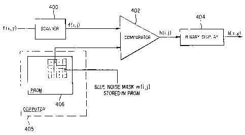
Figure 4 shows an example of the hardware which may be used for the digital
implementation of halftoning using a blue noise mask as discussed in the
instant
application. It should be understood that the hardware implementation can be
either digital
or analog, for example, using an operational amplifier in place of the
comparator 402 in the
analog case. It is a significant advantage of digital halftoning using a blue
noise mask that it
is much faster than the other known blue noise producing techniques, because
the halftoning
is done by a simple pixelwise comparison. The digital halftoning using a blue
noise mask
process of the present invention can be speeded up even further by performing
the
comparison step in parallel, since all of the thresholds are preassigned.
As shown in Figure 4, a scanner 400 is used to scan an image and convert the
pixels on that image from an array of f (x, y) to the gray scale image array f
(i, j). The
CA 02231816 1998-OS-15
- 25 -
output from the scanner 400 is fed to a first input of the comparator 402.
As previously described, the blue noise mask array m(i, j) is stored in the
PROM 406 which may be located in a computer 405. The output from the PROM 406
is
fed to the second input of the comparator 402. The output of the comparator is
the binary
image array h(i, j) which is fed to a binary display 404 which converts that
array into the
final image array h(x, y).
As previously discussed, the present halftoning using a blue noise mask
invention can also be implemented in an optical or photographic manner. An
example of an
optical application of the present halftoning system is the photographic
process used in
newspaper printing. Such a process can be either multiplicative or additive.
In the multiplicative photographic process, the gray scale image f(x, y) 500
is
photographed through the blue noise mask 502 which has a transmittance m(x, y)
and the
resultant superposition h(x, y) = f(x,y) x m(x, y) is printed onto high
contrast film 504, such
as high gamma film. That procedure is shown in Figure 5. It should be
understood that a
point fP in the array f(x, y) corresponds to a dot hp in the array h(x, y),
whose size and shape
depends on the gray level that fP represents.
Figure 6 shows the additive photographic process in which the blue noise
mask is added to the gray scale image at the film plane by a double exposure.
The gray
scale image array and blue noise mask array are added by adder 600 and then
fed to the high
gamma film 504 which produces the halftoned output. The adder 600 is in
simplest form a
repeated exposure of the film 504, where the image and the blue noise mask are
exposed
separately onto the film 504, which is then developed.
CA 02231816 1998-OS-15
-26-
In general, a gray scale photographic blue noise mask m(x,y) can be obtained
from a calculated array m(i, j) using a film printer such as a Dunn camera
interfaced to a
PROM or a computer. The conversion from discrete points to a continuous image
is then
given by equation (1). Print film or transparency film is exposed by the
computer controlled
film printer so as to produce a photographic blue noise mask.
The blue noise mask can also be used for halftoning in applications that
involve multibit and color displays. The digital halftoning process for a
binary display
using a blue noise mask (Figure 2) can also be expressed as follows:
h(i, j) = int {m (i, j) + f (i, j) } (6)
wherein int denotes integer truncation and the gray levels of m(i, j) and f
(i, j) vary between
0 and 1. In general, for a K-bit display, the output image array h(i, j) can
be written as
follows:
1
hK(i,j) = 2K-1 int{(2K - 1)m(i, j) + f(iJ)) (7)
The 2K - 1 threshold values are equally spaced between 0 and 1. A non-uniform
quantizer
is also possible.
It is also possible to modify the blue noise mask in order to minimize
undesirable printer and media dependent effects. That may be accomplished by
modifying
the first order statistics or the cumulative distribution function (CDF) of
the blue noise mask
(BNM). Such modification is useful in an environment such as medical
ultrasound imaging
CA 02231816 1998-OS-15
-27-
in which the user, using the present invention, may be able to select between
high and low
contrast images and the display and film characteristics of such medical
ultrasound imaging
equipment can be accounted for in each rendition.
In the case of blue noise masks, a large unstructured pattern of, for example,
256 x 256 pixel kernels provides sufficient degrees of freedom with which to
modify the
CDF so as to provide both linear and non-linear mappings of the input and
output. That
makes it possible to construct specialized blue noise masks for a particular
output printer.
Medium characteristics can also be minimized in such modified blue noise
masks.
Therefore, as will be described hereafter, the present invention provides for
the altering of
the cumulative distribution function of the blue noise mask that would
otherwise be utilized
so as to produce unique and more desirable input-output characteristics. While
three such
examples of such modified blue noise masks are discussed herein, those of
ordinary skill in
the art will readily recognize other ways in which to modify the blue noise
mask in order to
achieve similar results.
The first order statistics of the blue noise mask can be obtained directly
from
the mask itself as previously discussed. The method for modifying the mask
involves
taking each individual value of the mask and mapping it into a new value
(known as direct
value mapping), while avoiding certain extreme points of the blue noise mask.
In that
manner, the same, non-dumpy image can be produced. The mapping can be
performed in
such a manner that some undesirable printer output characteristics can be
eliminated. For
instance, when the output device produces low contrast images, the mapping can
be chosen
to modify the mask and the CDF of the mask in order to enable more pixels to
be deposited
CA 02231816 1998-OS-15
-28-
in the light and dark regions. That will result in the production of a higher
contrast image.
The mapping function operates on pixels of the blue noise mask, b(i, j), that
are equal to a specific value, g, and sets that specific value equal to a new
value, g':
for all b(i, j) = g - _) b' (i, j) = g' (8)
where f (g) = g' is a single valued, non-linear mapping function chosen to
alter the image
rendering, and b' (i, j) is the output, modified blue noise mask.
Figures 7-9 show diagrams of the flow charts for producing three different
modifications of the blue noise masks, the linear or punch version, the high
contrast concave
down sigma curve (CDSC) and the low contrast concave up sigma curve (CUSC).
All
versions include the "punch". Punching the blue noise mask means that the
extreme low
values are set to a certain minimum value, such as 0, and that the extreme
high values are
set to a certain maximum value, such as 255, and the values between the
maximum and
minimum values are then re-linearized.
The CDSC modification of the blue noise mask is accomplished by setting
F(g) = g3 which produces a "high contrast" mapping. The CUSC modification sets
f(g) = to g ~3, thus producing a flatter or low contrast curve.
After the modification of the blue noise mask is accomplished, halftoning of
the desired image using that mask is done in the manner previously described.
That is, the
halftoning is performed by comparing the values of the image with the values
of the
modified mask. If the value of the image is larger, the value of the new image
is rendered as
CA 02231816 1998-OS-15
-29-
black. Otherwise, the value of the new image will be set to white. The new
image is then
stored in a more compact form (reduced from 8-bits) because there is only one
bit per pixel
in a binary or halftone image. In the modified masks, each value in the blue
noise mask is
mapped to a new value based upon the variable selected by the user, such as
punch, CDSC
and CUSC. Halftoning is then performed based on those new values. By choosing
different
values, users can modify the image to eliminate artifacts and other defects
caused by the
specific printer and/or media being utilized.
The new halftone screens created using the modified CDF or gray scale
characteristics of the blue noise mask have non-linear input-output
characteristics. While
the gray scale characteristics of the blue noise mask are modified, the
isotropic,
unstructured, visually pleasing pattern of black and white pixels produced by
such blue
noise masks are preserved.
Figure 7 is a diagram of the flow chart for modifying a blue noise mask to
produce a linearized version of the initial blue noise mask. At step 700, the
value b(i ,j) = g
of the blue noise mask to be modified is read. At 702, the maximum and minimum
values
specified by the user are obtained. The values of the blue noise mask obtained
at step 700
are then re-linearized at step 704 by setting r = 25 S/(max-min) and then
calculating the
values of the modified blue noise mask b'(i, j) _ ( (b (i, j) ) - min)*r. In
this example, we
assume an 8-bit blue noise mask is being used, hence, max and min will lie
between 0 and
255, respectively.
A determination is then made at step 706 of whether each value of the
modified blue noise mask b' (i, j) is greater than the max value. If an
affirmative
CA 02231816 1998-OS-15
-30-
determination is made at step 706, then the value of that pixel b'(i, j) is
set equal to the max
value. After step 710 or if a negative determination is made at step 706, then
a
determination is made at step 708 of whether the value of the pixel of the
modified blue
noise mask b' (i, j) is less than the minimum value. If an affirmative
determination is made
at step 708, then the value of that pixel b' (i, j) is set equal to the
minimum value at step 712.
After step 712 or if a negative determination is made at step 708, the
modified blue noise
mask is assembled by writing the values of such modified blue noise mask b'
(i, j) into
memory at step 714.
Figure 8 shows a diagram of the flow chart for generating a modified high
contrast version of the blue noise mask. At step 800, the values of the blue
noise mask
b(i, j) = g are read. At step 802, the constants a, b, c which are to be
utilized in step 804 are
obtained from the user, as well as the max and min values. The constants a, b
and c are
chosen so as to generate unique mathematical mapping. The center point of
inflection is
given by the constant a, usually chosen near 128 for a symmetric, 8-bit mask.
The steepness
of the curve is given by the constant c and the offset of the curve, if
desired, by the constant
b.
Directly mapping occurs at step 804 in which each pixel value for the
modified blue noise mask b' (i, j) is calculated to be equal to (b(i, j) - a
)3 / c3 + b. This
function replaces a linear input-output relation with a steepened, non-linear
relation. The
linear input-output relation being replaced is shown, for example, in Figure
10 which shows
the CDF versus the value of pixels for a linear blue noise mask. Figure 11
shows the CDF
versus the value of pixels for a non-linear, high contrast blue noise mask,
after applying the
CA 02231816 1998-OS-15
-31 -
CDSC direct mapping with punch.
A determination is then made at step 806 of whether each new pixel value
b'(i, j) is greater than the maximum value. If an affirmative determination is
made at step
806, then the new pixel value b'(i, j) is set equal to the maximum value at
step 810. After
step 810 or if a negative determination is made at step 806, then a
determination is made at
step 808 of whether the new pixel value b'(i, j) is less than the minimum
value.
If an affirmative determination is made at step 808, then the new pixel value
b'(i, j) is set equal to the minimum value. After step 812 or if a negative
determination is
made at step 808, then the values of the modified blue noise mask b'(i, j) are
written into
memory at step 814.
Figure 9 shows a diagram of the flow chart for the modification of a blue
noise
mask to produce a CUSC low contrast version of the original blue noise mask.
The values
of the blue noise mask b(i, j) = g are read at step 900 and then the constants
a, b and c are
obtained, as well as the maximum and minimum values at step 902. Such
constants and
maximum and minimum values are provided by the user.
At step 904, a direct mapping process is accomplished in which the array of
values of the modified blue noise mask b'(i, j) is calculated as equal to
cbrt (b(i, j) - b)*c + a. This function, where "cbrt" stands for the cube
root, changes a linear
input-output relation to a low contrast, non-linear input-output relation. The
constants a, b
and c give the offset, center point and gain, respectively.
At step 906, a determination is made for each pixel of the blue noise mask of
whether its value is greater than the maximum value. Thus, a determination is
made of
CA 02231816 1998-OS-15
-32-
whether b'(i, j) is greater than the maximum value.
If an affirmative determination is made at step 906, then for each pixel in
the
array b'(i, j) which is greater than the maximum value, its value is set to
the maximum value
at step 910.
If a negative determination is made at step 906 or after step 910, a
determination is made at step 908 of which pixel value, if any, in the
modified blue noise
mask b'(i, j) is less than the minimum value. If an affirmative determination
is made at step
908, then for each pixel value in the modified blue noise mask b'(i, j) which
is less than the
minimum value, that value is set equal to the minimum value at step 912.
After step 912 or if a negative determination is made at step 908, the values
of
the modified blue noise mask b'(i, j) are written into memory at step 914.
The instant method can also be applied to color halftoning, by independently
thresholding each one of the component colors against the blue noise mask and
then
overprinting. In that manner, the blue noise mask disclosed herein can be
applied simply to
the component colors of RGB, CMYK and others for color printing. For example,
an
Optronix scanner can be used as the scanner 400 shown in Figure 4 to input
three separate
files of 8-bits in depth each, for the red, blue and green components of an
image. Prior to
displaying such image, a blue noise mask generated according to the method
disclosed
herein can be applied separately to each of the red, green and blue images.
The resulting
images may then be displayed on a binary RGB video screen or printed.
It has also been discovered that an improvement in the clarity of the
displayed
RGB image can be achieved when the pixels of the blue noise mask are shifted
by one pixel
CA 02231816 1998-OS-15
- 33 -
when used on the different color planes. For example, the (i, j) pixel of the
blue noise mask
can be shifted such that the blue noise mask which is applied to the red image
color plane
has each of its pixel values shifted up by one pixel when halftoning the red
image. When
halftoning the blue image, the blue noise mask has each of its pixel values
shifted by one
pixel to the side. In that manner, the color energy is spread out over a
larger space. It
should be noted, however, that no shifting of the RGB images with respect to
each other
occurs, as that would cause blurnng of the resulting image. Instead, as
discussed above, the
respective blue noise masks used to halftone the red and blue images have
their pixel values
shifted by one pixel up or to the side, respectively.
The foregoing method is shown in Figure 12 which is a diagram of a flow
chart for implementing halftoning of a color image using the foregoing method.
The color
image 1200 to be scanned is scanned by a scanner 400 to produce three
continuous tone
color planes 1202, 1204 and 1206, one for each of the three colors, red, green
and blue,
respectively. The values in each of these planes or arrays are added to the
blue noise mask
as shown in Figure 6. Alternatively, a comparator can be used, as shown in
Figure 4.
However, the (i, j) pixel of the red image is compared against the shifted (i
+ 1, j) pixel of
the blue noise mask. The (i, j) pixel of the green image is compared against
the (i, j) pixel
of the blue noise mask. The (i, j) pixel of the blue image is compared against
the (i, j + 1 )
pixel of the blue noise mask. Such comparisons take place at steps 1208, 1210
and 1212.
Each of these three planes or arrays are thresholded or are printed on high
gamma film a step 504 in order to produce three halftone images at steps 1214,
1216 and
1218. The halftone image hR (i, j) represents the (i, j) pixel of the halftone
red image. The
CA 02231816 1998-OS-15
-34-
elements at 1216 and 1218 likewise represent the halftone of the green and
blue images,
respectively. These images are combined at step 404 by a printer or display in
order to
produce a three color halftone image at step 1220. It should be noted that the
halftoning of
each of the components of the color image uses a shifted version of the blue
noise mask as
disclosed herein to produce a useful spreading out of the color without
introducing blur into
the halftone image.
A variation of this method of separately halftoning the different color planes
of
an image is to use the inverse of a blue noise mask for one color, where the
inverse is
defined as (Maxval - BNM) for each pixel. The Maxval is the maximum value of
the blue
noise mask (for example, 255 for the 8-bit blue noise mask). To produce the
modified blue
noise mask, the value of each pixel is subtracted from the Maxval to produce
each new
value for each pixel. This inverse process can be thought of as exchanging the
"peaks and
valleys of the blue noise mask", and results in the spreading out of the
energy in the color
pattern of the color image.
Many modifications of this process are likewise possible, such as different
one
shift patterns, or multiple shift patterns of the pixel values of a generated
blue noise mask.
While it has been found, for example, in low resolution 300 dpi systems, that
one pixel shift
produces a visually pleasing result, ten shifts have been found to produce an
annoying
correlation between different color dots while larger shifts of about forty-
five pixels produce
an acceptable, uncorrelated pattern of colored dots.
Of course, other possible modifications can also produce acceptable results,
for example, the placing of one color plane blue noise mask at 45° with
respect to another as
CA 02231816 1998-OS-15
-35-
is done inconventional four color printing. However, it has been found that
the simple one-
shift pattern described above is most effective at producing a pleasing,
isotropic, non-
clumpy moire resistant pattern with some spreading out of the color or ink but
with no
blurring of the image. Similar principles apply of course for CMYK color
printing, where
the halftoning can be done on the C, M and Y color images, and then the black
image (K)
can be added as necessary according to conventional color printing models.
Although only a preferred embodiment is specifically illustrated and described
herein, it will be readily appreciated that many modifications and variations
of the present
invention are possible in light of the above teachings and within the purview
of the
appended claims without departing from the spirit and intended scope of the
invention.