Note: Descriptions are shown in the official language in which they were submitted.
CA 02231829 1998-03-12
W O 97/141~6 PCT/GB~ 2302
GROUNDING F~ FCTRODE
This invention relates to an elongate conductive member suitable for use as a
grounding electrode. In particular it relates to an elongate conductive member
comprisin~ an inner conductive core, a surrounding jacket, and a particulate carbon
rich material contained between the jacket and the core. The invention also provides
methods of eleckically grounding articles using the elongate conductive member.
An elongate conductive member having the construction described above is
known, for use not as a grounding electrode, but as an impressed current corrosion
protection anode. WO9302311 (RK463) and GB 9411787.6 (B265), for example,
each describe an elongate member comprising (i) a continuous elongate core having a
resistivity at 23~C of less than Sx10~ ohm cm, and a resi~t~n~e at 23~ of less than 0.03
ohm/m (usually a metal), (ii) an element which is comprised of a conductive polymer
composition, which preferably has an elongation of at least 10% and surrounds and is
in eleckical contact with the core, and is at least 500 microns thick, (iii) a polymeric
fabric outer jacket, and (iv) contained with;n the polymeric jacket, a particulate carbon
rich material such as coke. Preferred materials for the polymeric jacket of the anodes
described in the earlier patent applications are said to be polymers, copolymers or
blends of polyacrylonitrile, partially or wholly halogentated aliphatic polymers,
particularly polyvinylidene chloride or fluoride polytetrafluoroethylene,
poly(ethylene-tekafluoroethylene), poly(ethylene-chlol~llifluoroethylene), polyvinyl
fluoride, polyvinylchloride and polyvinylacetate. Preferred materials based on
polyacrylonikiles are Dralon (Bayer), Orlon (Dupont), Courtelle (Courtaulds), Acrilan
(Monsanto), and Dolan (Hoechst). Especially preferred materials are modacrylic
polymers, that is a material comprising between 35% and 85% polyacrylonikile, for
example, Teklan (Courtaulds - which comprises 50/50
polyacrylonikile/polyvinylidene dichloride), Velicren (Enimont), SEF (Monsanto)
and Kaneklon (a vinyl chloride based composition supplied by Kanegafuchi).
Another preferred mzlteri~l is Saran (PVDC copolymer from Dow Chemical).
SUBSTITUTE SltEEr IRULE 26)
CA 02231829 1998-03-12
W 0 97/14196 PCT/~5CI~ 30Z
Another possible though less ~ler~ ed, m~teri~l is poly(butylene-terephth~l~te). The
preferred polymeric materials are selected in the earlier references to be particularly
acid and chlorine re~i~t~nt which was found to be important for good lifetime
performance of the elongate conductive members in an illlplessed current corrosion
protection system.
In the known illl~lessed current corrosion protection systems the elongate
conductive member is cormected, via a power supply of constant sign, to the article to
be protected from corrosion. Electrolyte, e.g. soil, is present between the article to be
protected from corrosion and the elongate conductive member, therefore completing a
circuit and an electrochemiGal cell. Electrical current flows from the electrode (which
acts as an anode) to the article, which acts as a cathode, to protect the article from
corrosion. Typically the current density of the protective current flowing from the
anode surface is of the order of 50 mA/m. Although current density values are often
given in units of A/m, for ~;ullc~ flowing from the surface of elongate electrodes it is
common practice to quote current densities in units of A/m, this being the total current
value per metre length of the elongate electrode. Elongate electrodes known in the art,
and used in the present invention typically have an outer diameter in the range 10 to
40mm.
The entire disclosures of W 09302311 and GB 941 1787, and their
corresponding US applications, are incorporated herein by reference.
We have now found that an elongate conductive member, having a similar
construction to that described in W093023 1 1 and GB 941 1787, but with an outerconductive jacket in place of the polymeric jacket of the references can be used as an
efficient electrical grounding member. This is surprising given that the elongate
conductive member is acting in a different electrical fashion in a grounding
application from in an impressed current corrosion protection system. In particular, it
is surprising since the current densities at discharge in a grounding application are of
SUBSTITUTE SHEEI (RULE 26)
CA 02231829 1998-03-12
W O 97/14196 PCT/GB96/02302
the order of about 300 to 2000 A/m, i.e. six to forty times as high as that involved in
impressed current corrosion protection systems.
Accordingly the present invention provides an elongate conductive member
comprising:
(i) an elongate core comprising a m~t.?ri~l having a resistivity at 23~C of less than
5xl0~ ohm cm and a reSict~n~e at 23~C of less than 0.03 ohm/meter;
(ii) a conductive polymer element that surrounds and is in electrical contact with
the core;
(iii) a jacket that surrounds the conductive polymeric element and is spaced
t~l&l~rl~lll; and
(iv) a carbon rich material in particulate form contained within the jacket, between
the jacket and the conductive polymeric element;
characterised in that the elongate conductive member is suitable for use as a
grounding electrode, and that the jacket material is electrically conductive, having a
resistivity of less than 100 ohm cm
The resistivity of the jacket m~t~ri~l iS preferably less than S0 ohm cm; more
preferably less than 30 ohm cm, especially less than 20 ohm cm, more especially less
than 10 ohm cm, even less than 5 ohm cm, or less than 2 ohm cm. An especially
pl~rt;ll~d material for the jacket is carbon fibre having a resistivity of about 1.4 ohm
cm.
The present invention preferably also provides a method of electrically grounding an
article comprising,
SUBSTITUTE SHEEr (RULE 26
CA 0223l829 l998-03-l2
W O 97/14196 PCT/GB96/02302
(i) providing an elongate conductive member according to the invention,
and
(ii) electrically connecting one end of the elongate conductive member to
the article to be grounded.
The core of the elongate conductive member of the present invention is
preferably a metal, for example copper. Preferably the core has a diameter in the
range of 2 to 10 mm. The core may comprise one or more wires.
The conductive polymeric element that surrounds, and is in electrical contact
with the core is preferably a layer having a thickness in the range 500xlO~~m to 20mm
thick. The conductive polymeric element preferably has a resistivity in the range 0.1
to 105 ohm cm, preferably 0.1 to 104 ohm cm, preferably 0.1 to 103 ohm cm,
particularly 1 to 100 ohm cm, especially 1 to 50 ohm cm.
As used herein, the term "conductive polymer" means a composition
compri~ing a polymer component, and dispersed therein a particulate conductive
filler, for example carbon black. The term "conductive polymer" includes those
compositions in which the polymer composition is a thermoplastic, a rubber or a
thermoplastic rubber. Examples of m~teri~l.c for the base polymer component include
acrylate rubbers, butyl or nitrile rubbers, olefin homopolymers, and copolymers, and
fluorinated or chlorinated polymers.
In a preferred embodiment according to the present invention, the electrically
conductive jacket of the grounding electrode is in the form of a fabric. Examples of
suitable fabric constructions include weaves, braids, knits, warp-inserted-weft knits
(WIWK), and the like. A particularly pler~.led jacket is a fabric jacket comprising
carbon fibre, or a fabric jacket compri~ing flexible conductive polymeric fibres.
Although a fabric jacket is preferred, non-fabric conductive jackets, for example a
continuous conductive polymeric jacket, are also envisaged.
SUBSTITUTE SHEET (RULE 26)
CA 02231829 1998-03-12
W O 97/141~6 PCT/GB96/02302
s
The multi layer construction of the elongate conductive member of the present
invention provides a balance of properties making it particularly effective as agrounding electrode. The inner (usually metal) highly conductive core ensures current
is tr~n~mitte~ rapidly away from the article to be grounded. The conductive
polymeric layer surrounding and in electrical contact with the inner core, protects the
inner core from rusting. Also the conductive polymeric layer, since it has a higher
radial re~i~t~nce than the inner core, acts to distribute the electrical current further
along the length of the elongate conductive member, prior to discharge into the
ground, than would be the case in the absence of the conductive polymeric layer. This
may enhance the lifetime of the grounding member, and avoids overheating at points
directly beneath the articles being electrically grounded. The carbon rich particulate
material, e.g. coke, surrounding the conductive polymeric layer reduces the resi~t~nce
to ground at any particular point along the conductive member, compared to the same
electrode in the absence of coke. The reduction in the rÇsict~nce to ground is achieved
primarily by the increase in surface area provided by the presence of the carbon rich
particulate m~teri~l A similar effect could be achieved, for example, by using a much
thicker conductive polymeric layer. However, this would be much more expensive.
The conductive jacket retains the coke, and facilitates h~n~llin?~ of the coke cont~inin~
electrode. The conductive nature of the jacket ensures the radial rç~i~t~nce to ground
is minimi~ed.
I he elongate conductive members according to the invention may vary in
length considerably. Preferred lengths range from 1 to 500 m. Different lengths are
plc;r~,led for different applications. For example, for grounding an article to resist a
lipht~ning pulse, which typically lasts for a period of the order of a few microseconds,
lengths of about lm are pler~ d. For grounding an article such as switchgear, which
may be subjected to ~ lL~ of the order of thousands of Amps for a period of about a
second, longer lengths, of several hundred metres, e.g. 200m, 300m or even 500m
may be plc;rellc~d. In general, the longer the time period in which current is p~c~in~,
the longer the preferred length of the conductive member of the present invention.
The length preferred also varies according to the soil resistivity in which the
SUBSTITIJTE SlrlEE~ (RULE 2~)
CA 0223l829 l998-03-l2
W O 97/14196 PCT/~ 30Z
conductive member is used. Where the length of the conductive member required islonger than about 50m, this may be provided by a single elongate conductive member,
or by joining several conductive members end to end.
Preferably an additional resistive member is used in conjunction with the
elongate conductive member of the present invention. The additional member is
preferably positioned to surround and to be in electrical contact with the end of the
elongate conductive member that is connected in use to the article to be grounded.
The shape and the resistivity of the additional resistive member are arranged to reduce
the flow of current from the elongate conductive member from the part thereof
surrounded by the resistive member. For example the additional resistive member
may be generally conical, the widest part of the cone being nearest the said end of the
elongate conductive member. The purpose of this additional resistive member is to
reduce the increased current density that would otherwise exit the elongate conductive
member at its point of connection to the article to be grounded. This feature isdescribed in British Patent Application (our reference B302 GBl) which is
filed contemporareously herewith. The entire disclosure of .. (B302 GBl), andany corresponding US application, is incorporated herein by reference.
The present invention preferably provides a kit of parts comprising an elongate
conductive member according to the invention, in combination with an additional
resistive member of the type described above, and a method of electrically grounding
an article using such a kit of parts.
The jacket of the elongate conductive member is preferably flexible, and used
in combination with tensioning wraps tensioned around the flexible jacket such that
the compaction of the particulate carbon rich material is increased relative to their
compaction in the absence of such wraps. The outer tensioning wraps may
advantageously be in the form of a braid. The flexible jacket of the elongate
conductive member is flexible to the extent that it can be deformed into different
configurations by movement of the particulate carbon rich material within it, and/or
SUE~5~ A _ _~L ~ L_ ~6)
CA 02231829 1998-03-12
- W O 97/141~6 PCT/GB96/02302
by the action of the tensioning wraps. The tensioning wraps preferably do not add
significantly to the overall radial resistance of the elongate conductive member.
Preferably the tensioning wraps comprise a material that has similar pl~f~ d
resistivity values to those stated above as being ~lcr~lled for the jacket of the elongate
conductive member.
In the event that a section of the jacket of the elongate conductive member is
damaged, it can be conveniently repaired by carrying out the following plc;r~ledmethod steps:
(i) securing annular portions of the jacket close to the conductive
polymeric element, on either side of the damaged section of jacket;
(ii) removing the damaged jacket section and particulate carbon rich
m~teri~l between the secured annular portions, to expose a length of
the conductive polymeric element;
(iii) positioning a repair sleeve (preferably wraparound) around, but spaced
from the exposed length of conductive polymeric element;
(iv) securing a first end of the repair sleeve to the underlying jacket;
(v) filling the space between the repair sleeve and the core with a carbon
rich particulate m~t~ri~l; then
(vi) securing the other end of the repair sleeve to the underlying jacket
The repair sleeve preferably has the same physical and electrical properties as
the jacket of the elongate conductive member.
SUBSTITUTE SI~IEET (RULE 26)
CA 02231829 1998-03-12
W O 97/14196 PCT/GB96/02302
Particular applications of the present invention include the grounding of
pipelines, high energy switch gear and buildings.
Embo~liment.e of the present invention are now described, by way of example,
with reference to the acconlpallyillg drawings, wherein
Figure 1 shows an eleckical grounding application in which the elongate
grounding member of the present invention can be used, and
Figure 2 shows in detail the elongate grounding member used in Figure 1.
Figure 1 shows an eleckical grounding application in which the elongate
grounding member of the present invention can be used. A building 1 to be protected
is conn~cte~l via an ine~ tc-l lead wire 3 to an elongate conductive member 5 buried
in soil 7.
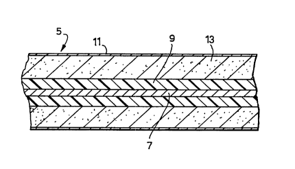
Figure 2 shows in detail the construction of the elongate conductive member 5.
The member 5 comprises a cylindrical copper core 7, a conductive polymeric element
in the form of a layer 9 surrounding and in electrical contact with the core 7, an outer
tubular carbon fibre woven jacket 11, and particulate coke 13 sandwiched between the
woven jacket 11 and the conductive polymeric layer 9. The outer diameter
measurement resistivity values of each of the components of the conductive member 5
are set out below in Table 1. The actual thickness of any particular layer may be
calculated by subkaction of the relevant outer diameter values.
Table 1
Outer diameter in Resistivity in
mm ohm.m at 20~c
Core 7 (copper) 4.11.8 x 10-~
Conductive
SUBSTITUTE SHEET (RULE 26)
CA 0223l829 l998-03-l2
W O 97/14196 PCTI~D~5.~302
polymeric element 9 13.0 1.5 x 10-'
Coke layer 13 37.0 1 x 10-~
Carbon fibre jacket
11 37.8 1.4x 10⁻²
Although the resistivity of the carbon fibre jacket is similar to that of the
conductive polymeric jacket, it contributes far less to the overall resi~t~nce of the
elongate conductive member, since it is much thinner than the conductive polymeric
element ~. In other words, the conductive polymeric element is the most significant
resistive member in the conductive member, and therefore controls the current flow
along, and ~ut of the conductive member.
The resistance to ground of an elongate conductive member according to the
invention, having the construction of Figure 2, was measured at 50 H~ in (i) soil
haying a ground resistivity of 2850 ohm cm, and (ii) soil having a ground resistivity
of 65000 ohm cm.
The resi~t~nce measurement was carried out by positioning the electrode according to
Figure 2 and a counter elongate electrode in the soil, generally parallel to each other,
but spaced apart, and applying a potential difference at 50Hz, between the two
electrodes. A re~ t~nce measuring electrode, also elongate in construction, was
positioned between the electrode according to the invention and the counter electrode.
As a colnl)~dLive control, an elongate conductive member having the same
construction as that shown in Figure 2, but with the carbon fibre jacket replaced by a
Velicren jacket was tested under the same conditions. Velicren in a polyacrylonitrile
based material supplied by Enimont. The results are set out in Table 2 below.
SUBSTITUTE SHEE~ (RULE 26)
CA 0223l829 l998-03-l2
W O 97/14196 PCT/GB9G~'~2~02
Table ?.
Resistance to ground ohms Resistance to ground in
as measured in soil of ohms, as measured in soil
resistivity 2850 ohm cm of resistivity 65000 ohm
cm
Figure 2 embodiment
(carbon fibre jacket) 20 395
Figure 2 embodiment with
carbon fibre jacket 9600 7300
replaced by a fabric poly
, acrylonitrile-based jacket
(comparative example)
As can be seen the resi~t~nce to ground is drastically reduced using a
conductive carbon fibre jacket co~ ~ed to the resistance to ground using a
polyacrylonitrile based jacket.
SUBSTITUTE SHEET ff~ULE 26)