Language selection

Search

Patent 2231878 Summary

Third-party information liability

Some of the information on this Web page has been provided by external sources. The Government of Canada is not responsible for the accuracy, reliability or currency of the information supplied by external sources. Users wishing to rely upon this information should consult directly with the source of the information. Content provided by external sources is not subject to official languages, privacy and accessibility requirements.

Claims and Abstract availability

Any discrepancies in the text and image of the Claims and Abstract are due to differing posting times. Text of the Claims and Abstract are posted:

  • At the time the application is open to public inspection;
  • At the time of issue of the patent (grant).
(12) Patent: (11) CA 2231878
(54) English Title: SINGLE-PIECE MOUNT WITH SPLIT METAL PLATES
(54) French Title: SUPPORT MONOBLOC A PLAQUES METALLIQUES FRACTIONNEES
Status: Deemed expired
Bibliographic Data
(51) International Patent Classification (IPC):
  • F16F 15/08 (2006.01)
  • B60K 5/12 (2006.01)
  • F16B 5/02 (2006.01)
  • F16F 1/373 (2006.01)
  • F16F 1/38 (2006.01)
(72) Inventors :
  • DORTON, DAVID W. (United States of America)
(73) Owners :
  • LORD CORPORATION (United States of America)
(71) Applicants :
  • LORD CORPORATION (United States of America)
(74) Agent: NORTON ROSE FULBRIGHT CANADA LLP/S.E.N.C.R.L., S.R.L.
(74) Associate agent:
(45) Issued: 2003-09-30
(86) PCT Filing Date: 1996-06-19
(87) Open to Public Inspection: 1997-03-20
Examination requested: 1999-08-25
Availability of licence: N/A
(25) Language of filing: English

Patent Cooperation Treaty (PCT): Yes
(86) PCT Filing Number: PCT/US1996/010572
(87) International Publication Number: WO1997/010466
(85) National Entry: 1998-03-12

(30) Application Priority Data:
Application No. Country/Territory Date
08/529,118 United States of America 1995-09-15

Abstracts

English Abstract


A single-piece elastomeric mount (22) installed over a plurality of openings
(15) has a like plurality of reinforcing plates (44 and 46) to permit the
elastomeric rib between the plates' edges to flex. The apertures (24 and 26)
in the mount can then be aligned with holes (15) in a support (13) having
wider tolerances on their end positions. The mount may include two sets of
plates - an upper load-distribution set (44 and 46) and a lower wear-reducing
set (30 and 32), each set being bonded to the elastomer.


French Abstract

L'invention porte sur un support monobloc élastomère (22) placé sur une pluralité d'ouvertures (15), lequel comprend une pluralité identique de plaques de renfort (44 et 46), la nervure élastomère située entre les bords des plaques étant ainsi flexible. Les orifices (24 et 26) pratiqués dans le support peuvent être alors alignés avec les ouvertures (15) pratiquées dans un support (13) et ayant des tolérances plus importantes aux extrémités. Le support peut inclure deux séries de plaques: une série supérieure (44 et 46) de répartition de charge, et une série inférieure (30, 32) réduisant l'usure, chacune de ces séries étant rattachée à l'élastomère.

Claims

Note: Claims are shown in the official language in which they were submitted.


Claims
What is claimed is:

1. An elastomeric mount, comprising:
a) a layer of elastomer;
b) at least two fastener-receiving apertures extending through said
elastomeric mount;
c) at least two separate substantially coplanar metallic plates, one
for each of said at least two fastener-receiving apertures adjacent a lower
surface of said layer of elastomer forming a first set of metallic plates to
provide a wear-protecting, load-distributing surface for said elastomer, each ofsaid at least two plates of said first set having an aperture which is coaxial
with its corresponding fastener-receiving aperture in said mount, said
fastener-receiving aperture being surrounded by a collar which has been
extruded from each of said at least two plates, and each of said plates being
bonded to said adjacent surface of said layer of elastomer, each of said at least
two plates having an end portion juxtaposed to an end portion of each of said
other at least two plates, said juxtaposed end portions forming pairs of end
portions, said elastomer forming a narrow rib between each of said pairs of
end portions;
whereby said narrow rib between each of said pairs of end portions of said at
least two separate metallic plates permits flexing of said elastomeric mount
enabling a distance between said at least two fastener-receiving apertures to beadjusted to accommodate variations in hole center spacing in a supporting
member to which said mount is attached.

2. The elastomeric mount of Claim 1 wherein said collar of each of
said at least two plates forms a recess with said plate and each of said recesses
is at least partially filled by said layer of elastomer.
3. The elastomeric mount of Claim 2 further comprising a second
set of separate metallic plates equal in number to said at least two
fastener-receiving apertures having apertures coaxial with each of said
fastener-receiving apertures in said mount, said second set of plates being positioned
adjacent said upper surface of said elastomer to distribute load.


4. The elastomeric mount of Claim 3 wherein each
fastener-receiving aperture in said mount is lined by a metallic sleeve extending
therethrough.
5. The elastomeric mount of Claim 4 wherein said at least two
metallic plates of said first set positioned adjacent said lower surface of saidelastomer are each formed as separate stampings, said extruded collar
non-engagingly receiving one of said metallic sleeves.
6. The elastomeric mount of Claim 5 further comprising a
deformable elastomeric boot surrounding and extending beyond said
metallic sleeve, said elastomeric boot being deformable to form a rebound
cushion.
7. The elastomeric mount of Claim 6 wherein a thickness of said
plate from said second set and said metallic sleeve form a fixed distance
between an underneath surface of a bolt head and an opposing surface of a
connected nut.
8. The elastomeric mount of Claim 7 wherein said fixed distance
between an underneath surface of a bolt head and an opposing surface of a
connected nut is generally equal to a thickness normally occupied by a
supported member, said elastomeric mount, said supporting member, said
elastomeric boot in a fully compressed position, and washer means against
which said connected nut seats, whereby said elastomeric boot operates as a
rebound cushion against an upward movement of said supported member
relative to said supporting member.


Description

Note: Descriptions are shown in the official language in which they were submitted.


CA 02231878 1998-03-12
W O 97/10466 PCTrUS96/10572


SINGLE-PIECE MOUNT Wl'l'~l SPLIT METAL PLATES

R~ck~round and Sllmn~ry ofthe Invention
This invention relates to the field of elastomeric mounts. More
5 particularly, the present invention is directed to a mount having split plates which increase wear resistance while permitting fl~xing of the mount to
permit variations in the support plate's hole spacing to be accommodated.
A concern arose regarding the wear life of a bushing mount being used
to support a diesel truck engine. The mount is a cylindrical center-bonded
10 bushing or grommet-style mount which was used in a flanged support that is
formed as a casting. A small diameter portion of the mount (the "shank")
extends through a hole formed in the support while a larger diameter portion
(the "head") rests on the surface of the support. The lower surface of the head
was expçrienring conqi(lerable wear as a result of the vibration-induced
15 movement between that surface and the rough cast surface of the support. In
~ ition, test parts developed .qignific~nt cracks at the transition point
between the shank and the head. Further the upper surface of the head
offered minimal surface area through which to react loads.
The present invention seeks to remedy whichever one of these
20 problems is most serious for a particular application by extending the mount
to reach between at least two holes in the supporting member and
incorporating a metallic plate into the upper or lower surface to reduce wear.
A problem arose when a single plate was provided that extended between the
two holes: in forming the casting, dowel rods are used to position the
2!; grommet-receiving holes in the support. As the molten metal is poured into
the casting, the dowel rods can be caused to move within a limited range of
poqitionq resulting in non-uniformity in the center hole spacing in the support.The lack of fl~xihilit.y in the mount caused by the wear-reducing plate
nece.q.qit~ted the customer to assume the additional expense of m~ hining
30 their part to provide a more uniform hole spacing or resulted in even greater additional costs associated with discarding out-of-spec castings.

CA 02231878 1998-03-12
W O 97/10466 P~T~US96/10572

To resolve this problem, the flexihility of the present mount is
~nh~nce-l by subdividing the reinforcement plate(s), with each fastener-
receiving aperture being provided with its own wear-re(lllrin~ and/or load
distributing plate. The elastomer between the surface plates serves as a
S fle~nhle spine or rib ~n~hling the center-to-center spacing of the apertures to
be ~exed to accommodate the out-of-spec hole spacing in the support. The
upper load-distributing plates ~i~ifi~ntly increase the surface area which
engages the supported member thereby more widely dist~ibuting the load. For
this particular applir~hc n, it is preferred that each aperture be provided with10 a set of both upper load-distributive plates and a set of lower wear-reducingplates, but some applications may require only one of these sets of plates.
Various other features, advantages and characteristics of the present
invention will become apparent after a reading of the following specification.

1~; Brief Description of the Drawirlgs
The drawings depict the preferred embodiments of the present
invention, lil~e items bearing lil~e lere. e~ce numerals in which
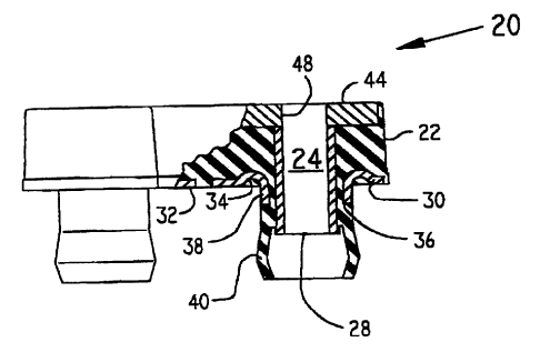
FIG. 1 is side view in partial cross section of a first embodiment of
the elastomeric mount of the present invention;
FIG. 2A is a top view of the embodiment depicted in Fig. l;
FIG. 2B is a bottom view of the Fig. 1 embodiment;
FIG. 3 is a cross-sectional side view of a portion of the mount of the
present invention shown in its installed position; and
FIG. 4 is a top view of a second embo~iment of the present invention.

~ --V~ CA 02231878 1998-03-12
IR qao2~r~
~PE 4/(JS
SEP 1 c i~

A fir~t emho~lim~nt of l~he ela~tomeric mount of t~ . t
en~o~ i~ 'ct~ in Fig. 1 generally at 20 A first f~ster~Pr -~ec4;~,~
&~ ULG 24 u~r~d~ t~rough arl elaatomenc layer 22 and is prefera~ly lined
5 by a center-bnn~l ~et llil~ sleeve 28. A 9eCOIld fa~tener ~ ,.ug nlJe,~u~
~ also e~ G~;L ~e el~ftQ ~ ~-r;r layer Z~ a~d i~ li~ed ~y a -e n~
~leeve (rlot shown). ~ltl~o~tgh the mount :~0 of this design i~ shown as a
grolmmet-type mou~t ha~ring center-bQn~l~A ~lee~es as, ~he Q~ e~ o~ this
inve~tiorl apply to other ~pes of mouIIts, as well.
A first set of metallic plates ~ . ZB) are ~ d to a lower
( ' ~urface 21 of elastomeric layer ~2 and, ~nAPe~ the ela~o~ may be
permitted to fill l~he recess ~4 ~c~ ' when central thro~gl~hore 36 is
- formed by ~h~ g coll~ ~ el~to~-~ic ~oot 40 i9 fi~-me~
al~ m~r extruded ke!tv~ sleeve~ and collar ~ for a ~o~e ~ be
15 described belo~v.
Upper pate6 4~ and 46 (F~ 5tA) are ~ou.~9~ he upper ~ rf -c~ 2B
f 1 - ---c iay~r :1., ~d hz~ "~;1"~,, ~8 ~d a~ C~ Yith
s 24 a~d ~ff, L~-~pa l ;~. ly. Upper plate~ 4* and 46 are ~ormed ~ith
sprue holos * to pe~mit ~he e1P~Pr of layer 2:~ tl~ be ;~ ~ A ~to the mold
20 Inot ~hown) therethro-lgh. A nb of ela~tomer ~;2 ~s f~,r~ 7 ~- L- ee.~ ~he ends
' j of the first ~et of plate~ 30, 32 an~ the ~econd set of plate~ 44, 48. Rib S2
permits the mount ~ be fle~ed to permit center bt~n~ I,ures 24, 26 to
~r~ mmndate ~ ti~n~ i~ center~ center spacing of hole~ JpVL~
13. T~e tenn~nal en~, of pairs of plates 30 and 44 aud sa a~d 48 are 8ho~1ru
~5 a~ being coplanar which is ~l~f~L~ed, although not n--?ssary.
As be~t seen in E'ig~ 3, nut 54 is ~hreaded onto er~d of bolt 56 ~ secure
S~L~PO~le~1 memb~r }1 to support 13. Support 13 ~s a rou~h finichetl cast
mPmh~r and plates 30, 32 cf the fir~t set of plates ~ilI prot~c~ elas~omeric
layer :Z2 from abrasion caused by rubbi~g as the sup~o~led mPml~r' a ~esel
30 enEin~, for example, vibrates relati~e to :,u~ 13. The supported member
11 (which may far example be an engi~e ~racket~, upper plates 44, 46,
slee~es Z8, and wa3her 58 provide a solid metallic path betwee~ the head of
bolt 56 and nut 54 permitting the elastomer of boot 40 to be collapsed as

3 AMEND~D SHEET

09/Ol '98 FRI 17:20 [TX/RX NO 5873]

_ ol/09~98 12:33 3053230 CA 0223l878 l998-03-l2'EP ~'7 WIP0 ~012
,, , , " ~, _ .,,, ,,, _ .. _ ... ..... _ . -- .
~R l~O~
~tP l ~ ~997,
sho~ in N~. 3. ~orm~lly, as mou~t 20 ~ t;~9 il:S half of ~Le diesel
engine load (or 1300 l}~s. each, two mounts 20 being used), the desig~ of the
mount will be ~uch ~at a slight gap will ope~ be~ oot 40 ~d the
nether surface of ~ul~urL 18. This gap ~ill Pnh~n.~e ~ibr~t~ colYtjc~n
5 In any case, boot 40 ser~es a~ a rebollnd c~ iQr. damping upward
movemeut of the ~u~ qd rnpmher 11 whic~ may be e~ e~ npin~
torque or roat bumps, for e~S~mrl~
The present mount waa te~te~l ~ a test fi~cture s~ st ~he
grn~net-style mount it replaced un~l eac~ mount was worn out (~lq~ - ~
10 as a 30~o re~lllr~ion i:n st;ff~ s~ The mouDt of the prese~t ~tion
schie~ed more ths~ an 8 fold increa3e i~ ~rear life (22L000 cycles Y8. Z5,0Q0
f cydes). ID addition, reduced wear on the underhead portion of 1~he mount
wa~ experienced a~ a resul~ of the pre~ence o~ plates 30, :~2 in spite of the
additional cycle~.
lS The advS~nfog~ of the p~e~.t mount design are not lim~~~ to
aprlir~;r~n to bushing l~ nor ~o ~no~ s ha~ing o 1y two
t.~-o~g}lb~reQ. A seoorl~ ~mb~imont is ~ f~ n Fig. 4 in ~rhicl~ mou~t
20' i9 shown having four f.~t~ r~ i~g a~.~r~.~.,c :Z4' each havi~e its
~Bte plate 44'. T~e horl7~nt~l ~d vertic~l ~b8 5~5' and ~ ~it t~e
20 s-liFn~-~nt of a~,e.t,.,e~i 24' to be v~ried to perm~t the mount :~0' to
~rc~ o~o1~e variQtions in center to center ~ rinE~ of a~.~ 16 in
;j a~ cl L 13. Ob~ously, the configu~ation shown is ~ d not
int~ ~e~ to be limi~ in any sense.
Various cha~lges, alte2~ati~ves and ~ ~ ;fic~SiorLs will becom~
25 apparent to one of ordinary skill in the art ~ollowin~ a reading of the
fu~egui~g spe~ifi~ tiqr It is inten~ at all such cha~lg~s, alternati~es
and moAi1ic~tions as fall within the scope of ~he ~pr~ claims be
c~ ci~lered part of the present invention.


AMFND~D StlEET


09/01 '98 FRI 17:20 [TX/RX N0 5873]

Representative Drawing
A single figure which represents the drawing illustrating the invention.
Administrative Status

For a clearer understanding of the status of the application/patent presented on this page, the site Disclaimer , as well as the definitions for Patent , Administrative Status , Maintenance Fee  and Payment History  should be consulted.

Administrative Status

Title Date
Forecasted Issue Date 2003-09-30
(86) PCT Filing Date 1996-06-19
(87) PCT Publication Date 1997-03-20
(85) National Entry 1998-03-12
Examination Requested 1999-08-25
(45) Issued 2003-09-30
Deemed Expired 2005-06-20

Abandonment History

There is no abandonment history.

Payment History

Fee Type Anniversary Year Due Date Amount Paid Paid Date
Registration of a document - section 124 $100.00 1998-03-12
Application Fee $300.00 1998-03-12
Maintenance Fee - Application - New Act 2 1998-06-19 $100.00 1998-06-17
Maintenance Fee - Application - New Act 3 1999-06-21 $100.00 1999-06-15
Request for Examination $400.00 1999-08-25
Maintenance Fee - Application - New Act 4 2000-06-19 $100.00 2000-06-12
Maintenance Fee - Application - New Act 5 2001-06-19 $150.00 2001-06-04
Maintenance Fee - Application - New Act 6 2002-06-19 $150.00 2002-06-07
Final Fee $300.00 2003-02-20
Maintenance Fee - Application - New Act 7 2003-06-19 $150.00 2003-06-19
Owners on Record

Note: Records showing the ownership history in alphabetical order.

Current Owners on Record
LORD CORPORATION
Past Owners on Record
DORTON, DAVID W.
Past Owners that do not appear in the "Owners on Record" listing will appear in other documentation within the application.
Documents

To view selected files, please enter reCAPTCHA code :


To view images, click a link in the Document Description column. To download the documents, select one or more checkboxes in the first column and then click the "Download Selected in PDF format (Zip Archive)" or the "Download Selected as Single PDF" button.

List of published and non-published patent-specific documents on the CPD .

If you have any difficulty accessing content, you can call the Client Service Centre at 1-866-997-1936 or send them an e-mail at CIPO Client Service Centre.


Document
Description 
Date
(yyyy-mm-dd) 
Number of pages   Size of Image (KB) 
Representative Drawing 1998-06-26 1 3
Representative Drawing 2003-08-27 1 8
Cover Page 2003-08-27 1 37
Abstract 1998-03-12 1 38
Description 1998-03-12 4 202
Claims 1998-03-12 2 87
Drawings 1998-03-12 2 46
Cover Page 1998-06-26 1 38
Assignment 1998-03-12 7 300
PCT 1998-03-12 13 511
Prosecution-Amendment 1999-08-25 1 48
Correspondence 2003-02-20 1 39
Correspondence 2003-07-24 1 13