Language selection

Search

Patent 2231957 Summary

Third-party information liability

Some of the information on this Web page has been provided by external sources. The Government of Canada is not responsible for the accuracy, reliability or currency of the information supplied by external sources. Users wishing to rely upon this information should consult directly with the source of the information. Content provided by external sources is not subject to official languages, privacy and accessibility requirements.

Claims and Abstract availability

Any discrepancies in the text and image of the Claims and Abstract are due to differing posting times. Text of the Claims and Abstract are posted:

  • At the time the application is open to public inspection;
  • At the time of issue of the patent (grant).
(12) Patent: (11) CA 2231957
(54) English Title: PLANT FOR PACKAGING CANS OR OTHER DISPOSABLE DRINK CONTAINERS, BY MEANS OF HEAT-SHRINKABLE FILM
(54) French Title: INSTALLATION POUR L'EMBALLAGE DE CANETTES ET AUTRES RECIPIENTS JETABLES POUR BOISSONS AU MOYEN D'UN FILM THERMORETRACTABLE
Status: Deemed expired
Bibliographic Data
(51) International Patent Classification (IPC):
  • B65B 9/02 (2006.01)
  • B65B 5/04 (2006.01)
  • B65B 9/06 (2012.01)
  • B65B 53/02 (2006.01)
  • B65B 53/06 (2006.01)
  • B65D 75/00 (2006.01)
  • B65B 9/06 (2006.01)
(72) Inventors :
  • BALLESTRAZZI, ARIS (Italy)
  • TASSI, LAMBERTO (Italy)
(73) Owners :
  • SITMA S.P.A. (Italy)
(71) Applicants :
  • SITMA S.P.A. (Italy)
(74) Agent: NORTON ROSE FULBRIGHT CANADA LLP/S.E.N.C.R.L., S.R.L.
(74) Associate agent:
(45) Issued: 2007-02-13
(22) Filed Date: 1998-03-12
(41) Open to Public Inspection: 1998-09-13
Examination requested: 2002-12-10
Availability of licence: N/A
(25) Language of filing: English

Patent Cooperation Treaty (PCT): No

(30) Application Priority Data:
Application No. Country/Territory Date
MI97A 000560 Italy 1997-03-13

Abstracts

English Abstract

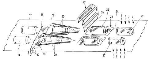
The plant for packaging cans or other disposable drink containers by means of heat-shrinkable film comprises: a support frame; at least two feed lines (13) for cans (11), with respective buffer zones (12), and with sensors (14) for sensing passage of an individual can (11); means (10) for feeding the cans recumbent and aligned into the at least two lines (13); means for feeding at least one heat-shrinkable film web (17) associated with means (20) for wrapping the film web over the cans of each line; a welding and cutting unit (21) with a longitudinal welder on each line and at least one welder (22) transverse to both said lines; a heat- shrinking tunnel (26) common to the various lines; and a package expulsion zone (28, 29).


French Abstract

L'installation pour l'emballage de canettes ou autres récipients de boissons jetables au moyen d'un film thermorétractable comprend : un châssis de support ; au moins deux conduites de distribution (13) pour les canettes (11), dotées de zones tampons respectives (12) et de capteurs (14) pour détecter le passage d'une canette individuelle (11) ; un moyen (10) pour l'alimentation des boîtes couchées et alignées à l'intérieur d'au minimum deux conduites (13) ; un moyen pour alimenter au minimum un film thermorétractable (17) associé à un moyen (20) d'emballer le film sur les boîtes de chaque conduite ; une unité de soudage et de découpe (21) avec un soudeur longitudinal sur chaque conduite et au minimum un soudeur (22) en position transversale par rapport auxdites conduites ; un tunnel de thermorétractation (26) commun aux différentes conduites ; et une zone d'expulsion d'emballage (28, 29).

Claims

Note: Claims are shown in the official language in which they were submitted.


-8-
CLAIMS:
1. A plant for packaging cans or other disposable
drink containers by means of heat-shrinkable film,
comprising:
a support frame;
at least two feed lines for cans, with
respective buffer zones, and with sensors for sensing
passage of an individual can;
means for feeding the cans recumbent and
aligned into the at least two lines;
means for feeding at least one heat-shrinkable
film web associated with means for wrapping said film web
over the cans of each line;
a welding and cutting unit with a longitudinal
welder on each line and at least one welder transverse to
both said lines;
a heat-shrinking tunnel common to the various
lines; and
a package expulsion zone.
2. A plant as claimed in claim 1, wherein said at
least two lines are side by side.
3. A plant as claimed in any one of claims 1 and
2, wherein said at least two lines are superposed one on
the other.
4. A plant as claimed in claim 1, comprising two
side-by-side lines and at least one further line lying
above or below said two side-by-side lines.


-9-
5. A plant as claimed in any one of claims 2 and
4, wherein said means for feeding at least one heat-
shrinkable film web comprise, for side-by-side lines, a
feeder for a film web having a width which is a multiple
of that necessary for a web required for each line, and
an element for the intermediate longitudinal cutting-to-
size of said web for an individual package.
6. A plant as claimed in claim 1, further
comprising a pitching device arranged to operate on the
various lines for transversely aligning cans advancing
along the various lines and for longitudinally spacing
them from the adjacent cans of the same line, and a
single transverse cutting and welding unit for the side-
by-side lines.
7. A plant as claimed in claim 1, comprising
within said expulsion zone a discharge conveyor for the
packaged cans and a device for expelling rejected
packages.

Description

Note: Descriptions are shown in the official language in which they were submitted.


CA 02231957 1998-03-12
PLANT FOR PACKAGING CANS OR OTHER DISPOSABLE DRINK CONTAINERS, BY
MEANS OF HEAT-SHRINKABLE FILM
This invention relates to a plant for packaging cans or other
disposable drink containers, by means of heat-shrinkable film.
It has already been proposed to package cans or other disposable
drink containers by means of 'heat-shrinkable film, for example in
Italian utility model application FI95U 000089 of 15.9.1995, but
without succeeding in defining a plant suitable for this packaging
because of ~ a series of constructional problems.
In this respect, to form such packages the plant must offer a high
production rate while being of relatively small overall size.
Moreover, because of the purpose for which it is intended, the
plant must be of low installation and operating cost, because
otherwise this additional packaging of the can or similar
container would increase its purchase price to an unacceptable
extent.
Consideration must also be given to the fact that the term "cans
or other disposable drink containers" includes not only the
traditional metal can but also any other container of glass,
plastic, impermeabilized food-quality cardboard, etc. In the
present description and in the embodiment shown on the drawings,


CA 02231957 2006-02-23
-2-
in all cases reference is made in particular to cans for
simplicity.
In accordance with a general aspect of the present
invention, there is provided a plant for packaging cars
or other disposable drink containers by means of heat-
shrinkable film, comprising:
a support frame;
at least two feed lines for cans, with
respective buffer zones, and with sensors for sensing
passage of an individual can;
means for feeding the cans recumbent and
aligned into the at least two lines;
means for feeding at least one heat-shrinkable
film web associated with means for wrapping said film web
over the cans of each line;
a welding and cutting unit with a longitudinal
welder on each line and at least one welder transverse to
both said lines;
a heat-shrinking tunnel common to the various
lines; and
a package expulsion zone.
Two or more lines can be arranged side by side, or
superposed, or some side by side and others superposed.
Advantageously, said film feed means can comprise, for
side-by-side lines, a unit for feeding a film web having
a width which is a multiple of that required for each
line; and an element for the intermediate longitudinal
cutting-to-size of said web for an individual package.
A pitching device can also be provided, for operating on
side-by-side lines to transversely align the cans of the
various lines and maintain them longitudinally spaced
apart by a predetermined

CA 02231957 1998-03-12
3
extent during their successive advancement. In this manner for
example a single welder can be used for transverse cutting and
welding, for several side-by-side lines.
Other characteristics will be apparent from the accompanying
claims.
The invention will be more apparent from the ensuing description
and the accompanying drawings, which show a non-limiting
embodiment of the invention. In the drawings:
Figure 1 is a very summary schematic plan view of the arrangement
of a plant according to the present invention comprising two side-
by-side lines; and
Figure 2 is a perspective view showing some of the operations
performed in the plant of the invention.
As shown in Figure 1, the reference numeral 10 indicates a feed
unit for cans 11, which feeds the cans to be packaged to a buffer
zone, indicated overall by 12. In the buffer zone 12 a double
feed line is formed from the various cans, which are distributed
for example on a set of friction rollers (not shown) in two
channels 13.
20 Suitable sensors 14 are provided in the form of sighting devices,
for the most part of photoelectric cell type, which monitor the
increasing and decreasing quantity so as to be able to control the
operation of the feed unit 10 which feeds cans to the buffer zone
12. The buffer zone 12 is supervised by an operator who checks
25 the regularity of the subdivision and of the feed to the
subsequent units, with the cans 11 correctly aligned
longitudinally.


CA 02231957 1998-03-12
- 4 -
The reference numeral 15 indicates a pitching device, arranged to
operate on each of the side-by-side lines to transversely align
the cans 11 of the various lines, and maintain them longitudinally
spaced apart by a predetermined extent during their successive
advancement. This spacing between successive cans, and the
transverse alignment of the pairs of side-by-side cans 11, is
particularly advantageous in the film covering and heat-shrinking
plant.
The pitching device 15 is followed by a packaging unit, indicated
overall by 16, which is formed to implement the packaging on the
two lines of spaced-apart cans transversely aligned in pairs, as
shown at 11' in Figure 2. A heat-shrinkable film web 17
originating from a reel (not shown) contained in the underlying
part of the plant frame can be fed into the packaging unit 16. In
particular, as there is only one web 17 in the illustrated
embodiment, it is divided by a cutting blade 18 (see Figure 2)
into two webs 19, each of sufficient width to wrap the can 11'
arriving from the respective Iine above the web 17 or above the
webs 19. In this case the feeder feeds a film web 17 having a
width which is a multiple of that necessary for a web 19 required
for each line, the cutter element 18 for longitudinal cutting
being positioned on the centre line of the web 17. In all cases
the longitudinal cutter element 18 is positioned intermediate to
the web at distances such as to form individual webs 19 suitable
25 for forming a single package. In a modified embodiment,
independently fed single webs 19 can be provided arranged on
respective reels, with enough reels provided to effect automatic


CA 02231957 1998-03-12
- 5 -
change without having to halt the entire plant.
The packaging unit also comprises guide means, shown schematically
at 20, which deviate the individual webs 19 of the film web 17
from a flat position to a position in which their longitudinal
5 edges are raised for their wrapping about an individual can 11'.
In this manner, the two webs 19 longitudinally wrap the
cylindrical wall of the respective cans 11' as they progressively
advance, and the free longitudinal edges become superposed one on
the other on the individual can 11'.
10 Downstream of the guide means 20 which perform this wrapping,
there is provided a welding and cutting unit, indicated overall by
21, comprising both longitudinal welding means, for example using
ionizing welders, and transverse welding means 22.
Advantageously, for side-by-side processing lines, a single
15 welding and cutting means 22 can be provided, which simultaneously
transversely welds and cuts the webs 19 which have been wrapped
about a can 11 on reaching 'the packaging unit on each of the
lines, along which the cans advance spaced apart.
In this manner, downstream of the entire welding and cutting unit
20 21 a covering 23 of heat-shrinkable film 19 is obtained about each
can 11. As shown in Figure 2, the covering 23 comprises front and
rear end transverse welds 24, and a longitudinal weld 25 formed
along superposed longitudinal edges of the individual web 19.
Following the packaging unit 20 there is a heat-shrinking tunnel
25 26, into which the cans of the two lines arrive, so that the
covering 23 of each can is .made to adhere by the effect of the
heat-shrinkage achieved in said tunnel 26. The heat-shrinkage


CA 02231957 1998-03-12
- 6 -
derives from the heat which in the direction of the arrows strikes
the covering 23 still positioned loosely about the can 11 and causes
the film to shrink adherent onto the can, as shown at 27.
This operation is followed by a discharge conveyor 29 for the
5 packaged cans and an expul:cion device for rejected packages, which
is indicated overall by 28 and is of known type, but has been
developed to operate on the: two side-by-side lines which reach the
expulsion zone, for removing the rejects.
The packaging rate achievable for cans 11 of traditional type of
10 about 33 cm3 of contents can be of the order of 400 cans per
minute, representing an appreciable production rate.
Notwithstanding this considerable processing rate for cans or
similar containers, the overall dimensions of the plant are of the
order of about twelve linear metres longitudinally and little more
15 than that of a traditional single-line plant transversely.
The said two or more lines can also be superposed, or the two or
more side-by-side lines can be arranged below one or more lines
positioned at a higher level.
At the plant exit, cans are obtained packaged in a substantially
20 sterile manner in terms of their subsequent use by the final
consumer. In this respect, this latter receives a can which has
been completely packaged and sealed in the factory, and hence in a
non-contaminated environment, so ensuring perfect hygiene on
consumption of the product contained in the can. It is also
25 hygienic to drink the liquid directly from the can by resting the
lips on the upper end of the can when opened in the traditional
manner by tabs which separate along incision lines typical of such


CA 02231957 1998-03-12
container cans.
The cans of each line can be made to advance with the axis of
their curved wall in the direction of advancement, or
perpendicular to this direction. The lines can be superposed, or
be in two series of side-by-side lines, the two series being
superposed one on the other.
The drawing shows only one non-limiting example of the invention,
which can be modified in terms of forms and arrangements without
leaving the scope of the concept on which the present invention is
based. The purpose of possible reference numerals in the ensuing
claims is merely to facilitate the reading of the claims with
reference to the description and the drawings, and does not limit
the scope of protection represented by the claims.

Representative Drawing
A single figure which represents the drawing illustrating the invention.
Administrative Status

For a clearer understanding of the status of the application/patent presented on this page, the site Disclaimer , as well as the definitions for Patent , Administrative Status , Maintenance Fee  and Payment History  should be consulted.

Administrative Status

Title Date
Forecasted Issue Date 2007-02-13
(22) Filed 1998-03-12
(41) Open to Public Inspection 1998-09-13
Examination Requested 2002-12-10
(45) Issued 2007-02-13
Deemed Expired 2014-03-12

Abandonment History

There is no abandonment history.

Payment History

Fee Type Anniversary Year Due Date Amount Paid Paid Date
Application Fee $300.00 1998-03-12
Registration of a document - section 124 $100.00 1999-01-12
Maintenance Fee - Application - New Act 2 2000-03-13 $100.00 2000-02-28
Maintenance Fee - Application - New Act 3 2001-03-12 $100.00 2001-02-27
Maintenance Fee - Application - New Act 4 2002-03-12 $100.00 2002-02-25
Request for Examination $400.00 2002-12-10
Maintenance Fee - Application - New Act 5 2003-03-12 $150.00 2003-02-28
Maintenance Fee - Application - New Act 6 2004-03-12 $150.00 2003-12-29
Maintenance Fee - Application - New Act 7 2005-03-14 $200.00 2005-02-16
Maintenance Fee - Application - New Act 8 2006-03-13 $200.00 2006-02-14
Final Fee $300.00 2006-11-27
Maintenance Fee - Patent - New Act 9 2007-03-12 $200.00 2007-02-13
Maintenance Fee - Patent - New Act 10 2008-03-12 $250.00 2008-02-08
Maintenance Fee - Patent - New Act 11 2009-03-12 $250.00 2009-02-12
Maintenance Fee - Patent - New Act 12 2010-03-12 $250.00 2010-02-18
Maintenance Fee - Patent - New Act 13 2011-03-14 $250.00 2011-02-17
Maintenance Fee - Patent - New Act 14 2012-03-12 $250.00 2012-02-08
Owners on Record

Note: Records showing the ownership history in alphabetical order.

Current Owners on Record
SITMA S.P.A.
Past Owners on Record
BALLESTRAZZI, ARIS
TASSI, LAMBERTO
Past Owners that do not appear in the "Owners on Record" listing will appear in other documentation within the application.
Documents

To view selected files, please enter reCAPTCHA code :


To view images, click a link in the Document Description column. To download the documents, select one or more checkboxes in the first column and then click the "Download Selected in PDF format (Zip Archive)" or the "Download Selected as Single PDF" button.

List of published and non-published patent-specific documents on the CPD .

If you have any difficulty accessing content, you can call the Client Service Centre at 1-866-997-1936 or send them an e-mail at CIPO Client Service Centre.


Document
Description 
Date
(yyyy-mm-dd) 
Number of pages   Size of Image (KB) 
Representative Drawing 1998-09-18 1 9
Cover Page 1998-09-18 1 61
Drawings 1998-03-12 1 32
Abstract 1998-03-12 1 19
Description 1998-03-12 7 205
Representative Drawing 2007-01-17 1 13
Cover Page 2007-01-17 1 48
Claims 1998-03-12 2 45
Drawings 2006-02-23 1 32
Claims 2006-02-23 2 46
Description 2006-02-23 7 211
Assignment 1999-01-12 2 87
Assignment 1998-03-12 3 109
Correspondence 1998-06-02 1 30
Prosecution-Amendment 2002-12-10 2 47
Correspondence 2003-01-03 1 44
Prosecution-Amendment 2003-05-21 2 52
Prosecution-Amendment 2005-08-30 2 45
Prosecution-Amendment 2006-02-23 6 149
Correspondence 2006-11-27 1 35