Language selection

Search

Patent 2232046 Summary

Third-party information liability

Some of the information on this Web page has been provided by external sources. The Government of Canada is not responsible for the accuracy, reliability or currency of the information supplied by external sources. Users wishing to rely upon this information should consult directly with the source of the information. Content provided by external sources is not subject to official languages, privacy and accessibility requirements.

Claims and Abstract availability

Any discrepancies in the text and image of the Claims and Abstract are due to differing posting times. Text of the Claims and Abstract are posted:

  • At the time the application is open to public inspection;
  • At the time of issue of the patent (grant).
(12) Patent: (11) CA 2232046
(54) English Title: GLAZING BARS
(54) French Title: PETITS BOIS
Status: Expired and beyond the Period of Reversal
Bibliographic Data
(51) International Patent Classification (IPC):
  • E04D 3/08 (2006.01)
  • E04B 7/00 (2006.01)
(72) Inventors :
  • RICHARDSON, CHRISTOPHER (United Kingdom)
(73) Owners :
  • ULTRAFRAME (UK) LIMITED
(71) Applicants :
  • ULTRAFRAME (UK) LIMITED (United Kingdom)
(74) Agent: MARKS & CLERK
(74) Associate agent:
(45) Issued: 2004-08-17
(22) Filed Date: 1998-03-12
(41) Open to Public Inspection: 1999-09-12
Examination requested: 2000-01-13
Availability of licence: N/A
Dedicated to the Public: N/A
(25) Language of filing: English

Patent Cooperation Treaty (PCT): No

(30) Application Priority Data: None

Abstracts

English Abstract


A glazing bar system comprises a support beam (10), upper and lower
cappings (12, 14 respectively) locatable on the beam, an end cap (68) therefor
and
means (61) for mounting the end cap on the support beam end.


Claims

Note: Claims are shown in the official language in which they were submitted.

5
What is Claimed is:
1. A glazing bar system comprising a support beam, upper cappings locatable on
the beam, an end cap therefor, and means for mounting the end cap on the
support
beam end, which comprises a bracket securable to the support beam end, wherein
the
bracket and the end cap have mutually engagable formations whereby they
slidingly
interfit.
2. A system as claimed in claim 1, wherein the beam has lower cappings
locatable thereon.
3. A system as claimed in claim 1, wherein the bracket is securable to the end
of
the support beam by means of a screw through the bracket into a screw port of
the
support beam.
4. A system as claimed in claim 1, wherein one of the bracket and the end cap
provides a pair of facing channels and the other has a pair of oppositely
facing lugs,
which are a sliding fit in the channels.
5. A system as claimed in claim 4, wherein the bracket provides a pair of
opposed ends or lugs spaced from the beam end to receive cooperating internal
formations of the end cap in sliding relationship.
6. A system as claimed in claim 5, wherein the end cap has a pair of opposed L-
shaped projections on its internal face to provide said internal formations in
the form
of facing channels.
7. A system as claimed in claim 1, wherein the end cap has a rim that is
deeper at
its top, whereby the end cap when fitted covers the end of the upper capping.

Description

Note: Descriptions are shown in the official language in which they were submitted.


CA 02232046 2003-10-28
GLAZING BARS
This invention concerns improvements relating to glazing bars.
Glazing bars for constructing roofs of conservatories generally comprise
aluminium support beams, between which are mounted glazing panels and upper
and
lower cappings to secure and seal the roofing panels and conceal the aluminium
beams. Typical glazing beams are of inverted T-section with a channel shaped
capping fitted to the cross bar of the T-section and an upper capping which
has
divergent sides and internally a means for connecting the upper capping to the
top of
the aluminium beam, usually in a press fit manner. Top ends of the glazing
bars are
concealed beneath ridge covers but their lower ends at the eaves of a
conservatory
structure need to be covered. At present an end cap is screwed to the
aluminium
glazing beam end, which is formed with a screw port for that purpose.
However, there are disadvantages with this system. Firstly, of course, the
head of the screw or screws used to secure the end cap is or are unsightly,
even when
masked. Secondly, the screw or screws used are liable to corrosion and to
allow
water ingress into the glazing bar.
An object of this invention is to provide an improved system for securing end
caps to glazing bars in order to avoid or mitigate against the above mentioned
disadvantages.
In accordance with one aspect of the present invention there is provided a
glazing bar system comprising a support beam, upper cappings locatable on the
beam,
an end cap therefor, and means for mounting the end cap on the support beam
end,
which comprises a bracket securable to the support beam end, wherein the
bracket and
the end cap have mutually engagable formations whereby they slidingly
interfit.
The means for mounting the end cap on the support beam end is preferably a

CA 02232046 1998-06-22
2
bracket securable to the support beam end. The bracket is preferably securable
to the
end of the support beam by means of a screw through the bracket into a screw
port of
the support beam.
The bracket and the end cap preferably have mutually engageable formations
whereby they slidingly interfit. One of the bracket and the end cap preferably
provides a pair of facing channels and the other has a pair of oppositely
facing lugs or
the like which are a sliding fit in the channels.
The bracket preferably provides a pair of opposed ends or lugs spaced from
the beam end to receive cooperating internal formations of the end cap in
sliding
relationship. The end cap preferably has a pair of opposed L-shaped
projections on
its internal face to provide said formations in the form of facing channels.
The end cap preferably has a rim that is deeper at its top, whereby the end
cap
when fitted covers the end of the upper capping.
The invention will now be further described, by way of example only, with
reference to the accompanying drawings, in which:
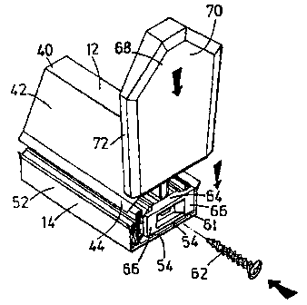
Figure 1 is a front perspective view of a glazing bar system of the invention;
Figure 2 is a rear view of the glazing bar system of Figure 1; and
Figure 3 is a further view of the glazing bar system of Figure 1.
Referring to the accompanying drawings, a glazing bar system comprises a
support beam 10 of aluminium and upper and lower cappings 12, 14 respectively
of
u-PVC. In use roofing panels, such as of transparent plastics material, for
example
polycarbonate, will have their edges sandwiched between the upper and lower
cappings on opposite sides of the roof beam arrangement.

CA 02232046 2003-10-28
3
The support beam 10 is generally of inverted T-section. Thus, the beam 10
has a pair of flanges 16, which are turned back on themselves at their remote
ends,
and an upstanding limb 18. The limb 18 comprises a stem 20 extending from the
junction of the flanges 16 to a screw port 22, a hollow generally triangular
section
main part 24 above the screw port and an upwardly open channel 26 above the
main
port. The channel 26 has generally parallel sides. On the inside of each side
is a
series of notches 30 forming downwardly open recesses.
Each flange 16 has a first part generally perpendicular to the upstanding limb
18 and a second part which forms a trough 34 remote from the upstanding limb
18.
The upper capping 12 is generally of inverted V-section but comprises a flat
top 40
and depending sides 42. The remote edges of the sides 42 have gaskets 44
formed
thereon by co-extrusion of rubber or synthetic elastorneric material.
Internally of the
capping 12 and depending from its flat top 40 are a pair of resilient
divergent flaps 46
having outwardly projecting lips 48 at their ends.
The lower capping 14 is generally formed as a channel section having a flat
base 50 and upstanding side walls 52. Internally of the channel on the base 40
and
on the side walls 52 are spacing projections 54. The free edges of the side
walls 52
have co-extruded thereon, from rubber or synthetic elastomeric material,
gaskets 56
which extend inwardly and are inclined slightly upwardly. The gaskets 56
include
resiliently deformable projection 58 and 60 on their upper surface along their
outermost edges and 62 centrally thereof.
To assemble a roof using the glazing bars, the aluminium support beams 10
are fixed in position between a ridge and the eaves of a conservatory roof.
The lower

CA 02232046 2003-10-28
4
cappings 14 are fitted onto the beams either before or after the beams are
fixed in
place. The glazing panels are positioned between the beams with their side
edges on
the gaskets 56, which are thereby trapped between the beam flanges and the
glazing
panels. Then the upper cappngs are pressed down onto the beams with their
deformable flaps being trapped in the upwardly open channels of the support
beams.
At the end of the support beam 10 a bracket 61 is fixed by means of a screw
62 through the bracket into the screw port 22 of the support beam: The bracket
61
has a wider central section 64 and narrower opposed ends 66, whereby the ends
are
spaced from the end of the support beam. An end cap 6$ for the glazing bar has
a
main surface 70 and a rim 72. On its intended inner face the end cap 68 has a
pair of
L-shaped projections 74 forming two facing open channels, which can be slid
over the
ends of the bracket to fit the end cap to the glazing bar.
The end cap rim 72 is of sufficient depth to extend rearwards over the ends of
the upper and lower cappings. The rim widens to a central part 74 at the top
of the
cap, to ensure that the cap rests on the top of the upper capping when slid
into place
on the bracket.
Thus, the illustrated end cap provides a neat and simple to complete finish to
the glazing bars for a conservatory roof.

Representative Drawing
A single figure which represents the drawing illustrating the invention.
Administrative Status

2024-08-01:As part of the Next Generation Patents (NGP) transition, the Canadian Patents Database (CPD) now contains a more detailed Event History, which replicates the Event Log of our new back-office solution.

Please note that "Inactive:" events refers to events no longer in use in our new back-office solution.

For a clearer understanding of the status of the application/patent presented on this page, the site Disclaimer , as well as the definitions for Patent , Event History , Maintenance Fee  and Payment History  should be consulted.

Event History

Description Date
Time Limit for Reversal Expired 2008-03-12
Letter Sent 2007-03-12
Inactive: Late MF processed 2006-06-06
Letter Sent 2006-03-13
Grant by Issuance 2004-08-17
Inactive: Cover page published 2004-08-16
Pre-grant 2004-06-03
Inactive: Final fee received 2004-06-03
Notice of Allowance is Issued 2003-12-04
Letter Sent 2003-12-04
Notice of Allowance is Issued 2003-12-04
Inactive: Approved for allowance (AFA) 2003-11-26
Amendment Received - Voluntary Amendment 2003-10-28
Inactive: S.30(2) Rules - Examiner requisition 2003-04-28
Amendment Received - Voluntary Amendment 2000-03-13
Letter Sent 2000-02-09
Request for Examination Received 2000-01-13
Request for Examination Requirements Determined Compliant 2000-01-13
All Requirements for Examination Determined Compliant 2000-01-13
Inactive: Cover page published 1999-09-12
Application Published (Open to Public Inspection) 1999-09-12
Inactive: IPC assigned 1998-07-17
Inactive: First IPC assigned 1998-07-17
Inactive: IPC assigned 1998-06-25
Classification Modified 1998-06-25
Inactive: First IPC assigned 1998-06-25
Amendment Received - Voluntary Amendment 1998-06-22
Inactive: Single transfer 1998-06-16
Inactive: Courtesy letter - Evidence 1998-06-02
Inactive: Filing certificate - No RFE (English) 1998-05-28
Filing Requirements Determined Compliant 1998-05-28
Application Received - Regular National 1998-05-27

Abandonment History

There is no abandonment history.

Maintenance Fee

The last payment was received on 2004-02-24

Note : If the full payment has not been received on or before the date indicated, a further fee may be required which may be one of the following

  • the reinstatement fee;
  • the late payment fee; or
  • additional fee to reverse deemed expiry.

Please refer to the CIPO Patent Fees web page to see all current fee amounts.

Fee History

Fee Type Anniversary Year Due Date Paid Date
Registration of a document 1998-03-12
Application fee - standard 1998-03-12
Request for examination - standard 2000-01-13
MF (application, 2nd anniv.) - standard 02 2000-03-13 2000-02-22
MF (application, 3rd anniv.) - standard 03 2001-03-12 2001-02-20
MF (application, 4th anniv.) - standard 04 2002-03-12 2002-02-18
MF (application, 5th anniv.) - standard 05 2003-03-12 2003-02-24
MF (application, 6th anniv.) - standard 06 2004-03-12 2004-02-24
Final fee - standard 2004-06-03
MF (patent, 7th anniv.) - standard 2005-03-14 2005-02-08
MF (patent, 8th anniv.) - standard 2006-03-13 2006-06-06
Reversal of deemed expiry 2006-03-13 2006-06-06
Owners on Record

Note: Records showing the ownership history in alphabetical order.

Current Owners on Record
ULTRAFRAME (UK) LIMITED
Past Owners on Record
CHRISTOPHER RICHARDSON
Past Owners that do not appear in the "Owners on Record" listing will appear in other documentation within the application.
Documents

To view selected files, please enter reCAPTCHA code :


To view images, click a link in the Document Description column. To download the documents, select one or more checkboxes in the first column and then click the "Download Selected in PDF format (Zip Archive)" or the "Download Selected as Single PDF" button.

List of published and non-published patent-specific documents on the CPD .

If you have any difficulty accessing content, you can call the Client Service Centre at 1-866-997-1936 or send them an e-mail at CIPO Client Service Centre.


Document
Description 
Date
(yyyy-mm-dd) 
Number of pages   Size of Image (KB) 
Representative drawing 1999-09-01 1 10
Description 2003-10-28 4 158
Claims 2003-10-28 1 33
Drawings 2003-10-28 2 44
Cover Page 1999-09-01 1 25
Abstract 1998-06-22 1 6
Description 1998-06-22 4 151
Claims 1998-06-22 1 33
Drawings 1998-06-22 2 42
Description 1998-03-12 4 134
Claims 1998-03-12 1 30
Drawings 1998-03-12 2 40
Abstract 1998-03-12 1 6
Representative drawing 2004-07-14 1 11
Cover Page 2004-07-14 1 31
Filing Certificate (English) 1998-05-28 1 162
Courtesy - Certificate of registration (related document(s)) 1998-08-25 1 140
Reminder of maintenance fee due 1999-11-15 1 111
Acknowledgement of Request for Examination 2000-02-09 1 180
Commissioner's Notice - Application Found Allowable 2003-12-04 1 160
Maintenance Fee Notice 2006-05-08 1 172
Late Payment Acknowledgement 2006-06-15 1 165
Maintenance Fee Notice 2007-04-23 1 172
Correspondence 1998-06-02 1 28
Correspondence 2004-06-03 1 47