Sélection de la langue

Search

Sommaire du brevet 2232046 

Énoncé de désistement de responsabilité concernant l'information provenant de tiers

Une partie des informations de ce site Web a été fournie par des sources externes. Le gouvernement du Canada n'assume aucune responsabilité concernant la précision, l'actualité ou la fiabilité des informations fournies par les sources externes. Les utilisateurs qui désirent employer cette information devraient consulter directement la source des informations. Le contenu fourni par les sources externes n'est pas assujetti aux exigences sur les langues officielles, la protection des renseignements personnels et l'accessibilité.

Disponibilité de l'Abrégé et des Revendications

L'apparition de différences dans le texte et l'image des Revendications et de l'Abrégé dépend du moment auquel le document est publié. Les textes des Revendications et de l'Abrégé sont affichés :

  • lorsque la demande peut être examinée par le public;
  • lorsque le brevet est émis (délivrance).
(12) Brevet: (11) CA 2232046
(54) Titre français: PETITS BOIS
(54) Titre anglais: GLAZING BARS
Statut: Périmé et au-delà du délai pour l’annulation
Données bibliographiques
Abrégés

Abrégé anglais


A glazing bar system comprises a support beam (10), upper and lower
cappings (12, 14 respectively) locatable on the beam, an end cap (68) therefor
and
means (61) for mounting the end cap on the support beam end.

Revendications

Note : Les revendications sont présentées dans la langue officielle dans laquelle elles ont été soumises.


5
What is Claimed is:
1. A glazing bar system comprising a support beam, upper cappings locatable on
the beam, an end cap therefor, and means for mounting the end cap on the
support
beam end, which comprises a bracket securable to the support beam end, wherein
the
bracket and the end cap have mutually engagable formations whereby they
slidingly
interfit.
2. A system as claimed in claim 1, wherein the beam has lower cappings
locatable thereon.
3. A system as claimed in claim 1, wherein the bracket is securable to the end
of
the support beam by means of a screw through the bracket into a screw port of
the
support beam.
4. A system as claimed in claim 1, wherein one of the bracket and the end cap
provides a pair of facing channels and the other has a pair of oppositely
facing lugs,
which are a sliding fit in the channels.
5. A system as claimed in claim 4, wherein the bracket provides a pair of
opposed ends or lugs spaced from the beam end to receive cooperating internal
formations of the end cap in sliding relationship.
6. A system as claimed in claim 5, wherein the end cap has a pair of opposed L-
shaped projections on its internal face to provide said internal formations in
the form
of facing channels.
7. A system as claimed in claim 1, wherein the end cap has a rim that is
deeper at
its top, whereby the end cap when fitted covers the end of the upper capping.

Description

Note : Les descriptions sont présentées dans la langue officielle dans laquelle elles ont été soumises.

CA 02232046 2003-10-28
GLAZING BARS
This invention concerns improvements relating to glazing bars.
Glazing bars for constructing roofs of conservatories generally comprise
aluminium support beams, between which are mounted glazing panels and upper
and
lower cappings to secure and seal the roofing panels and conceal the aluminium
beams. Typical glazing beams are of inverted T-section with a channel shaped
capping fitted to the cross bar of the T-section and an upper capping which
has
divergent sides and internally a means for connecting the upper capping to the
top of
the aluminium beam, usually in a press fit manner. Top ends of the glazing
bars are
concealed beneath ridge covers but their lower ends at the eaves of a
conservatory
structure need to be covered. At present an end cap is screwed to the
aluminium
glazing beam end, which is formed with a screw port for that purpose.
However, there are disadvantages with this system. Firstly, of course, the
head of the screw or screws used to secure the end cap is or are unsightly,
even when
masked. Secondly, the screw or screws used are liable to corrosion and to
allow
water ingress into the glazing bar.
An object of this invention is to provide an improved system for securing end
caps to glazing bars in order to avoid or mitigate against the above mentioned
disadvantages.
In accordance with one aspect of the present invention there is provided a
glazing bar system comprising a support beam, upper cappings locatable on the
beam,
an end cap therefor, and means for mounting the end cap on the support beam
end,
which comprises a bracket securable to the support beam end, wherein the
bracket and
the end cap have mutually engagable formations whereby they slidingly
interfit.
The means for mounting the end cap on the support beam end is preferably a

CA 02232046 1998-06-22
2
bracket securable to the support beam end. The bracket is preferably securable
to the
end of the support beam by means of a screw through the bracket into a screw
port of
the support beam.
The bracket and the end cap preferably have mutually engageable formations
whereby they slidingly interfit. One of the bracket and the end cap preferably
provides a pair of facing channels and the other has a pair of oppositely
facing lugs or
the like which are a sliding fit in the channels.
The bracket preferably provides a pair of opposed ends or lugs spaced from
the beam end to receive cooperating internal formations of the end cap in
sliding
relationship. The end cap preferably has a pair of opposed L-shaped
projections on
its internal face to provide said formations in the form of facing channels.
The end cap preferably has a rim that is deeper at its top, whereby the end
cap
when fitted covers the end of the upper capping.
The invention will now be further described, by way of example only, with
reference to the accompanying drawings, in which:
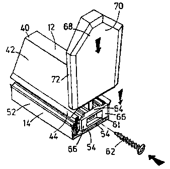
Figure 1 is a front perspective view of a glazing bar system of the invention;
Figure 2 is a rear view of the glazing bar system of Figure 1; and
Figure 3 is a further view of the glazing bar system of Figure 1.
Referring to the accompanying drawings, a glazing bar system comprises a
support beam 10 of aluminium and upper and lower cappings 12, 14 respectively
of
u-PVC. In use roofing panels, such as of transparent plastics material, for
example
polycarbonate, will have their edges sandwiched between the upper and lower
cappings on opposite sides of the roof beam arrangement.

CA 02232046 2003-10-28
3
The support beam 10 is generally of inverted T-section. Thus, the beam 10
has a pair of flanges 16, which are turned back on themselves at their remote
ends,
and an upstanding limb 18. The limb 18 comprises a stem 20 extending from the
junction of the flanges 16 to a screw port 22, a hollow generally triangular
section
main part 24 above the screw port and an upwardly open channel 26 above the
main
port. The channel 26 has generally parallel sides. On the inside of each side
is a
series of notches 30 forming downwardly open recesses.
Each flange 16 has a first part generally perpendicular to the upstanding limb
18 and a second part which forms a trough 34 remote from the upstanding limb
18.
The upper capping 12 is generally of inverted V-section but comprises a flat
top 40
and depending sides 42. The remote edges of the sides 42 have gaskets 44
formed
thereon by co-extrusion of rubber or synthetic elastorneric material.
Internally of the
capping 12 and depending from its flat top 40 are a pair of resilient
divergent flaps 46
having outwardly projecting lips 48 at their ends.
The lower capping 14 is generally formed as a channel section having a flat
base 50 and upstanding side walls 52. Internally of the channel on the base 40
and
on the side walls 52 are spacing projections 54. The free edges of the side
walls 52
have co-extruded thereon, from rubber or synthetic elastomeric material,
gaskets 56
which extend inwardly and are inclined slightly upwardly. The gaskets 56
include
resiliently deformable projection 58 and 60 on their upper surface along their
outermost edges and 62 centrally thereof.
To assemble a roof using the glazing bars, the aluminium support beams 10
are fixed in position between a ridge and the eaves of a conservatory roof.
The lower

CA 02232046 2003-10-28
4
cappings 14 are fitted onto the beams either before or after the beams are
fixed in
place. The glazing panels are positioned between the beams with their side
edges on
the gaskets 56, which are thereby trapped between the beam flanges and the
glazing
panels. Then the upper cappngs are pressed down onto the beams with their
deformable flaps being trapped in the upwardly open channels of the support
beams.
At the end of the support beam 10 a bracket 61 is fixed by means of a screw
62 through the bracket into the screw port 22 of the support beam: The bracket
61
has a wider central section 64 and narrower opposed ends 66, whereby the ends
are
spaced from the end of the support beam. An end cap 6$ for the glazing bar has
a
main surface 70 and a rim 72. On its intended inner face the end cap 68 has a
pair of
L-shaped projections 74 forming two facing open channels, which can be slid
over the
ends of the bracket to fit the end cap to the glazing bar.
The end cap rim 72 is of sufficient depth to extend rearwards over the ends of
the upper and lower cappings. The rim widens to a central part 74 at the top
of the
cap, to ensure that the cap rests on the top of the upper capping when slid
into place
on the bracket.
Thus, the illustrated end cap provides a neat and simple to complete finish to
the glazing bars for a conservatory roof.

Dessin représentatif
Une figure unique qui représente un dessin illustrant l'invention.
États administratifs

2024-08-01 : Dans le cadre de la transition vers les Brevets de nouvelle génération (BNG), la base de données sur les brevets canadiens (BDBC) contient désormais un Historique d'événement plus détaillé, qui reproduit le Journal des événements de notre nouvelle solution interne.

Veuillez noter que les événements débutant par « Inactive : » se réfèrent à des événements qui ne sont plus utilisés dans notre nouvelle solution interne.

Pour une meilleure compréhension de l'état de la demande ou brevet qui figure sur cette page, la rubrique Mise en garde , et les descriptions de Brevet , Historique d'événement , Taxes périodiques et Historique des paiements devraient être consultées.

Historique d'événement

Description Date
Le délai pour l'annulation est expiré 2008-03-12
Lettre envoyée 2007-03-12
Inactive : TME en retard traitée 2006-06-06
Lettre envoyée 2006-03-13
Accordé par délivrance 2004-08-17
Inactive : Page couverture publiée 2004-08-16
Préoctroi 2004-06-03
Inactive : Taxe finale reçue 2004-06-03
Un avis d'acceptation est envoyé 2003-12-04
Lettre envoyée 2003-12-04
Un avis d'acceptation est envoyé 2003-12-04
Inactive : Approuvée aux fins d'acceptation (AFA) 2003-11-26
Modification reçue - modification volontaire 2003-10-28
Inactive : Dem. de l'examinateur par.30(2) Règles 2003-04-28
Modification reçue - modification volontaire 2000-03-13
Lettre envoyée 2000-02-09
Requête d'examen reçue 2000-01-13
Exigences pour une requête d'examen - jugée conforme 2000-01-13
Toutes les exigences pour l'examen - jugée conforme 2000-01-13
Inactive : Page couverture publiée 1999-09-12
Demande publiée (accessible au public) 1999-09-12
Inactive : CIB attribuée 1998-07-17
Inactive : CIB en 1re position 1998-07-17
Inactive : CIB attribuée 1998-06-25
Symbole de classement modifié 1998-06-25
Inactive : CIB en 1re position 1998-06-25
Modification reçue - modification volontaire 1998-06-22
Inactive : Transfert individuel 1998-06-16
Inactive : Lettre de courtoisie - Preuve 1998-06-02
Inactive : Certificat de dépôt - Sans RE (Anglais) 1998-05-28
Exigences de dépôt - jugé conforme 1998-05-28
Demande reçue - nationale ordinaire 1998-05-27

Historique d'abandonnement

Il n'y a pas d'historique d'abandonnement

Taxes périodiques

Le dernier paiement a été reçu le 2004-02-24

Avis : Si le paiement en totalité n'a pas été reçu au plus tard à la date indiquée, une taxe supplémentaire peut être imposée, soit une des taxes suivantes :

  • taxe de rétablissement ;
  • taxe pour paiement en souffrance ; ou
  • taxe additionnelle pour le renversement d'une péremption réputée.

Veuillez vous référer à la page web des taxes sur les brevets de l'OPIC pour voir tous les montants actuels des taxes.

Historique des taxes

Type de taxes Anniversaire Échéance Date payée
Enregistrement d'un document 1998-03-12
Taxe pour le dépôt - générale 1998-03-12
Requête d'examen - générale 2000-01-13
TM (demande, 2e anniv.) - générale 02 2000-03-13 2000-02-22
TM (demande, 3e anniv.) - générale 03 2001-03-12 2001-02-20
TM (demande, 4e anniv.) - générale 04 2002-03-12 2002-02-18
TM (demande, 5e anniv.) - générale 05 2003-03-12 2003-02-24
TM (demande, 6e anniv.) - générale 06 2004-03-12 2004-02-24
Taxe finale - générale 2004-06-03
TM (brevet, 7e anniv.) - générale 2005-03-14 2005-02-08
TM (brevet, 8e anniv.) - générale 2006-03-13 2006-06-06
Annulation de la péremption réputée 2006-03-13 2006-06-06
Titulaires au dossier

Les titulaires actuels et antérieures au dossier sont affichés en ordre alphabétique.

Titulaires actuels au dossier
ULTRAFRAME (UK) LIMITED
Titulaires antérieures au dossier
CHRISTOPHER RICHARDSON
Les propriétaires antérieurs qui ne figurent pas dans la liste des « Propriétaires au dossier » apparaîtront dans d'autres documents au dossier.
Documents

Pour visionner les fichiers sélectionnés, entrer le code reCAPTCHA :


Pour visualiser une image, cliquer sur un lien dans la colonne description du document. Pour télécharger l'image (les images), cliquer l'une ou plusieurs cases à cocher dans la première colonne et ensuite cliquer sur le bouton "Télécharger sélection en format PDF (archive Zip)" ou le bouton "Télécharger sélection (en un fichier PDF fusionné)".

Liste des documents de brevet publiés et non publiés sur la BDBC .

Si vous avez des difficultés à accéder au contenu, veuillez communiquer avec le Centre de services à la clientèle au 1-866-997-1936, ou envoyer un courriel au Centre de service à la clientèle de l'OPIC.


Description du
Document 
Date
(aaaa-mm-jj) 
Nombre de pages   Taille de l'image (Ko) 
Dessin représentatif 1999-09-01 1 10
Description 2003-10-28 4 158
Revendications 2003-10-28 1 33
Dessins 2003-10-28 2 44
Page couverture 1999-09-01 1 25
Abrégé 1998-06-22 1 6
Description 1998-06-22 4 151
Revendications 1998-06-22 1 33
Dessins 1998-06-22 2 42
Description 1998-03-12 4 134
Revendications 1998-03-12 1 30
Dessins 1998-03-12 2 40
Abrégé 1998-03-12 1 6
Dessin représentatif 2004-07-14 1 11
Page couverture 2004-07-14 1 31
Certificat de dépôt (anglais) 1998-05-28 1 162
Courtoisie - Certificat d'enregistrement (document(s) connexe(s)) 1998-08-25 1 140
Rappel de taxe de maintien due 1999-11-15 1 111
Accusé de réception de la requête d'examen 2000-02-09 1 180
Avis du commissaire - Demande jugée acceptable 2003-12-04 1 160
Avis concernant la taxe de maintien 2006-05-08 1 172
Quittance d'un paiement en retard 2006-06-15 1 165
Avis concernant la taxe de maintien 2007-04-23 1 172
Correspondance 1998-06-02 1 28
Correspondance 2004-06-03 1 47